When you click on links to various merchants on this site and make a purchase, this can result in this site earning a commission. Affiliate programs and affiliations include, but are not limited to, the eBay Partner Network.
So I just picked up two Blaster 2 High Vibe coils to replace my currently leaky (and clicking) coils, and I decided to look into the DLIDFIS mod that I had seen a few time while perusing the forum. My question is as follows: The 1980 ignition systems are known for their issue with crossfire due to the electronics being mounted separately (I have also noticed this myself while setting the timing). With my currently installed system, there are only the two J-105 ignitors (no spares), although I also I have an '82 dizzy with at least four spare J-109's. I don't know if the spares work, but the dizzy has two and it came off a running car. I'm trying to decide between which set-up to go with. I don't intend on cutting up the '80 system, in which that case requires me to source a new block connector for the harness. I feel like the '82 is the way to go, with a custom harness and all, I'm just curious of any reasons to do otherwise.
The car is a 1980 with no rats nest and a redone (simplified) engine harness.
On the 1980 ignition, does anyone know at what point in the system the interference is introduced? My guess is the wires going to and from the dizzy for the ignitors, which would be another reason to swap the '82 as the trailing could remain on the dizzy, separate from the rest of the system.
For context, the stud/bolt that holds the distributor in place snapped off a while ago (red loctite plus old/small studs I suppose; red was sure a dumb idea...). Right now the dizzy bracket is "glued" with loctite to the iron which has held ok so far, but it isn't a secure solution and doesn't let me change the timing. Anyway, the dizzy has to come out to give me the best chance of removing the stud without having to drill and tap the front iron for a new one.
I'll also be creating an "ignition box" to house the new set-up in, excluding the coils. I've got some aluminum sheet, and I figure I could make a fairly clean install with custom box and a fan to keep everything cool. I'm gonna make this look good, unlike my recent '94 alt swap which still needs to be tidied up.
Use the later FB distributor with either the J-109s or 4 pin Gm Hei modules. The later distributor pickups generate a much better,cleaner signal and the wider the airgap the better up to .035 limit. .032 is a good number to go for.
I favor the Hei module WITH a proper heat sink. There are brands available rated at @7 amps that paired with the right coil(s) give you about as strong a spark as you can get this side of a magneto. You'll need good wires to transfer juice from coils to plugs. 8.5 mm wires would be good. You will see faster plug wear with these upgrades so upgrading plugs is a good idea. After some experimenting with different plugs,i settled with RX8 Denso Iridium Racing plugs. Not cheap but no wear after about 10k miles. I would go thru 2 sets of NGK BR9EQ14 in same mileage
Going the J109 route,a fresh set of NGK wires would get the job done and original NGK plugs would give you a good foundation. When assembling your wire harness,include a relay to power modules/coils direct from battery. This will give your new system yet more punch as the 30+year old wiring/ignition switch see a volt drop of 1-1.5 volts which makes a noticeable difference in coil output. Gives switch and wiring a break too as the load goes to the milliamps it takes to power the relay.
Though I am an '80 purist at heart, I have to agree; doing anything tricky with the ignition will be easier with the later design. Larger body of knowledge about it and tricks you can do with it available. Simpler and more moddable design, and no need to fool around with fooling the trailing-ignition-cutoff-under-acceleration emissions "feature" of the 80 control box, which was only useful with the thermal reactor in place.
Been there, done that. Use the 82 dizzy and the rest of the advice GSLSEforme just gave you. Its spot on. The cooling of the HEIs just needs to be passive. Mount them on some sheet aluminium with some CPU paste and you are good. In my setup (linked in my sig) I just reused the base from the 80 ignition box (since my circuit board was fried) and drilled/tapped some extra holes to mount the HEIs.
I also had my mounting stud break off on my dizzy. I couldn't get it out, so I drilled it out and used JB weld to put a stud in and thats working fine.
Thanks for all the great info and suggestions with the dizzy and all. I will be using the '82 dizzy as per y'all's suggestion and I might go the GM ignitor route (probably, but we'll see). The job is still a couple weeks off though, and I just received my new coils today.
The primary resistance on the blaster coils is 0.7 ohms compared to the stock ... (I don't remember the spec off the top of my head). I'm not worried about it after I do the DLIDFIS mod, but for the time being I figured I'd throw the new coils in to see if I was having any 'major' issues with the old ones. Will the lower resistance (again, I'm not sure how much lower) potentially damage the J-105's of which I have no replacements for?
So when you do the DLIDFIS, you gut the igniter. You can even eliminate it if you want to and run the wires right into the dizzy where the igniter plugs in. That's what I do. You plug the wires into the spot where your leading igniter is. I use the GM HEI's with heat sinks but I only set the new coils up for the leadings. I leave the stock trailing J109 igniter and system in place. It's trailing spark after all. I've done this on a REPU and on a First Gen (83). Everything has been fine. I actually use Ford Coils (TFI) Wells 5C1116, 4 pin HEI Coils AC Delco D1906, (Wells DR100) , and heat sinks are AC Delco 10474610.
Yep, I had planned on gutting an ignitor to keep the look a little cleaner on the leading, while leaving the trailing as is. One of my goals with this is to keep things looking neat and tidy, plus of course the benefits of DLIDFIS. I'm planning on making a "closed" box with fans to keep everything extra cool, while also routing all the wires cleanly through a harness - we'll see how that turns out . I found the DR100's at autozone for 21.99 a pop, so that's a fairly compelling reason to ditch the J-109's.
Once I get the project going I'll update more frequently. For the time being though I'll be designing the layout of the box and cleaning up the '82 dizzy.
@t_j_farrell, that JB weld solution sounds like a good plan in case I end up in the same boat. I'll be keeping that in mind.
Don't gut a working igniter,no sense in that,they're getting harder to find. You said you had some extra ones? Test them all ,you'll probably find a bad one in the bunch. I know you're intending to build a box that's fan cooled. I'd recommend against that for a couple,three reasons.
1st adding too much complication,properly heat sinked,the igniters will be more than adequately ventilated by moving air in engine compartment. Putting them in any enclosure,fan or not will certainly shorten their life,and last,a running fan motor in close proximity to low voltage AC wires from pick up coils very likely to add emi to the signal coming to igniter.Possible misfire. Try to keep it simple,sturdy but simple. At some point you will have to get to the wiring,igniters for troubleshooting or repair.
Oh yeah, I never planned on gutting a good igniter. No sense in wasting a hundred-plus dollar part, especially when the trailing is still going to be using them. I'm fairly certain I've got a dead one (I'll test it to make sure). I hadn't thought about the issues with EMI from the fan, good thought there. Maybe, hmm.... I'll have to rethink that one. Perhaps a halfway shroud that the wires could tuck into while still leaving the igniters exposed for optimal passive cooling? I'll give that some thought over the next while.
Is there a good way to bench test igniters, or is the best solution to throw them in the car and test them that way?
Thanks Toruki for for link. While I didn't make a permanent tester, I did cobble some wires together and confirm I've got at least one dead J-109. Not sure what all the testing outcomes are, but the 'test lamp' (I used a multi-meter instead) never shut off on the unknown J-109, while on a known good one it did. The good one had zero volts across C and ground until I gave the + on the dizzy side power, and the other igniter was showing voltage regardless of what I did. So anyway, I'm glad I found a dead one cause that'll help make this just a little cleaner.
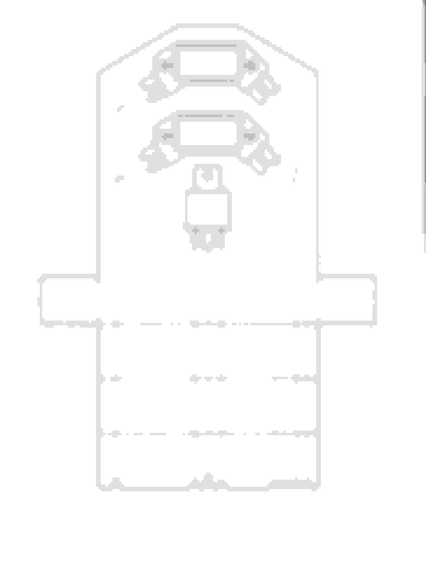
I did some thinking on the design of the mounting solution and this is what I came up with (this isn't necessarily a scale sketch but the placement is accurate. Sorry for the lack of labels.):
I'm still working out the best way to mount this in the engine bay, and also I'd like to change this so that each of the wires (other than the pickup wires) have their own notch to go through - replacing those holes with notches so that the wires can stay flush to the main plate. I'd also like to run the wires from the trailing igniter (still stock) through the same harness as the pickup from the leading but I'm worried EMI might be an issue there. Thoughts?
I'll be throwing this in CAD either tomorrow or this weekend so I'll post that once it's complete. I'm also picking up the last of the supplies this weekend so if anyone has any suggestions for atypical extras to add in, let me know! As of now I'm planning on running either 14 or 16 gauge for the reluctor wires and 10 for the coils/relay. I'm not sure what to run for the trailing igniter though. The work in the car will be happening shortly after Christmas, although in the meantime I'll fab the mounting plate and the wiring harnesses. I've also still got to clean up that '82 dizzy.
So to wrap all the questions in one place:
Was I correct in presuming that the J-109 I tested is dead?
Overall thoughts on the design.
Will EMI be an issue if I run the leading pickup wires and the trailing coil wires in the same harness and if so, will it be enough to cause harm or other undesirable effects?
Wire size suggestions for the leading reluctor, trailing igniter, and coils.
Any undocumented helpful extras to add in the shopping or to-do list?
Thanks everyone for the help thus far
Last edited by Benjamin4456; Dec 20, 2018 at 07:25 PM.
Twist the signal wire pairs from the dizzy and keep them as short as possible. Shielding doesn't hurt either. Using 14 gauge will work fine for signals, 12 is good for coils.
Thanks for the suggestion on the wire sizes. I'll be picking up parts tomorrow.
For the time being though, here is the plan. Do note that this is the template for the flat sheet, and it's also missing the mounting points to the car.
While this jpeg isn't to scale, the CAD file is accurate down past the mm (or so I hope). I measured and plotted the igniters (dr-100's) and relay I'm using and then made the back plate to accommodate. The dashed lines are bend marks and the colored are indicating which wires run to which hole. Maybe if I have some time, I'll make the whole thing 3D just for kicks - probably not worth it though.
Hopefully tomorrow or Sunday I can figure out where this is going and create the mounting appropriately. I'm also looking at fixing the mess my fuse-able link box has become at the same time as doing the rest of the work, so that might free up another mounting option.
If you haven't made your parts run yet a couple of suggestions...consider using 18 ga. wire for signal wires from dist. pickups to location where igniters are mounted. The voltage/signal generated by pickups in dist. is very low. .5 at idle speeds to a max of about 2 volts at hi rpm and using large ga. wire to transmit the signal,the longer the run of harness the better chance for signal degradation is at igniter as it seems to be absorbed in the thicker wire. The wires in dist.from pickup to connector for igniter are of small gauge for same reason.
18 ga. wire is easier to twist properly,makes a smaller neater package. All connections should be crimped/soldered/heat shrinked for best signal/voltage transfer for approx 3' of harness from dist to fenderwell area.
Another suggestion is to use a single pair of wires to transfer signal from dist to igniters for couple reasons,1st,its easier to make a single connection at pickup/gutted igniter than to make two for a total of four wires and two twisted pairs of wires for a long run. A much cleaner setup(less bulky)and cutting chance of signal degradation by 50% at igniter. 2nd reason is less amount of total wire needed. Only necessary for a second pair of twisted signal wires 2-3" long piggybacked from one igniter to second igniter.
14 ga. wire more than sufficient to carry power/grounds for coils and even hi amp igniters. No real need for thicker ga. wiring as its more bulky and more difficult to package in tight confines.
Well you did catch me before my parts run. I ended up taking an 'average' of y'all's advice plus what I've found in the existing threads on the subject. Thus said, I picked up some 16 ga. and 12 ga. - I needed 12 ga. for something else anyways. I've also restocked my crimp and heat shrink selection so now all I'm waiting for is the relays which are on their way. I might start building the plate tomorrow, we'll see. Couldn't figure out a good, locally obtainable solution for the fuse block so it looks like it'll stay put for the time being.
And yes, I was planning on using only one pair of wires to run from the leading pickup to the igniters where they would then split like you said.
Are y'all running fuses on your relay and coils/igniters and if so, what amp rating would you recommend? I feel like a single 20 would be about right for everything?
When the unknown key-bind on your new keyboard refreshes the page and auto-save didn't catch the memo... Oh well.
So anyway, I had been saying that I "have now joined the not-so-exclusive club of DLIDFIS" - so yeah; spent most of yesterday on the install and I'd say I'm pleased with the results. Pictures will find their way in somewhere.
So for the positives thus far:
Smell seems better, and considering my poorly tuned nikki (I haven't touched it since removing my leaky ACV) and a catless exhaust, I'd say it's about what I'd expect.
The sound is a little different. Idle sounds about the same, although up in the rpm's it's certainly changed. Oddly, the terrible buzzing sound that occurs randomly from my exhaust seems to have subsided (it's only noticable from the interior and I'm still working out where it's coming from).
The car idles much quicker without choke on cold starts.
And now for the "ehh's?"
Power seems indistinguishable from before the swap. Not much extra in the low end or up top. I will say, though, that power was not a specific goal of this swap - it just seemed like most people noticed a low end power bump after the work. Not a negative, not a positive. I'll also say that I haven't really had a chance to fully open it up yet since the roads are all slick with this lovely rain, so I'll update again this coming week with the drier weather. And I'm sure there's a little something extra; the seat-dyno just hasn't picked it up yet.
Quicker start-up's? Another claim people make is the "one-click" start up. From my one-day (yes, limited I realize) experience, neither cold or hot starts are "one-click". I wasn't really expecting instant start up's, and honestly before the swap, a few cranks was all it took and it's same case now. Again no negative or positive, just an observation.
I'd say that covers the majority of observations, although I do have a couple of questions left. I ran the leading signal wires as per the many wiring diagrams I found (or so I think). Just to be sure, I swapped them around and I didn't notice much of a change on start up, but the car idled lower, and was much more throaty. Reving seemed similar, although with the different sound of course. Any thoughts on which way things go? The original way seemed a little smoother, although that could've just been due to the higher idle.
The idle is also not without a few 'misfires' or bumps. It's perhaps a little better over the '80's cross-talk prone ignition system, although it's minimal at best. Don't get me wrong, I'm probably expecting more than more than reasonable - it's not as though it will ever be perfectly smooth. My bet is not the ignition system, but rather the tuning of the carb. The biggest proponent behind that theory is that while decelerating, I still get quite a lot of backfiring (although that could be ignition related nonetheless). From what others have said in similar threads, it sounds like backfiring essentially disappears after doing DLIDFIS, other than when you've been on the secondaries for a while. Any thoughts about this? I should also note that I'm still using the NGK wires, and the plugs that I installed much too long ago, so there's a good chance some of the issues are due to either of those. Perhaps tomorrow I will have time to check the plugs as I haven't done that for a while.
I've also noticed what seems like inconsistent power, or random flat spots throughout the power band. My first assumption is that I am hitting slick spots (manhole covers, etc.) on the road and the tires are spinning momentarily, although I'm not entirely sure as it doesn't feel like it. Would the addition of the better, more consistent ignition have amplified issues in other systems such as poor carb tuning? I most commonly get this effect in higher gears (3rd and 4th; haven't gotten 5th yet), and it acts like slight delays or even pulsing fluctuations after getting on the gas to accelerate. They are minor, but noticeable. Again, I'll really know how things are acting once I can get on a road that isn't so slick, and where traction is more consistent.
For the time being that wraps up what I can remember. I know there were a couple of other things, but they've slipped my mind for the moment. Here's some pictures of the install - you will notice I ditched the enclosed 'wire-box' for simplicity. Also, don't pay attention to the colors of the leading signal wires as I found the correctly sized connectors for the smaller G terminal, and then proceeded to solder them to the wrong wire color .
Oh, just noticed I should clean up that extra thermal paste :p
I also took this opportunity to fully clean the 'new' dizzy that came from my '82 parts car. The non-aluminum parts were sprayed with clear coat to prevent rust, and I'd say it came out fairly well. I cleaned up the internals too, but here's some pictures of the exterior (pardon the one blurry photo).
Well I'd say that covers it. If y'all could give some input on the various oddities mentioned above, that would be awesome.
Thanks for the help
Update: I just figured I'd throw out there that I managed the whole swap without doing any mods to the body (the battery tray was already 'modified' by the PO so I just added the bars and coil bracket). The mounting holes were all reused from removed parts, and I only spliced one existing wire which was the coil power for the leading which now serves as the relay signal.
Last edited by Benjamin4456; Dec 29, 2018 at 11:52 PM.
There's only one way to attach pickup wires to ignition modules. You must maintain polarity from pickup to module. Failing to do this causes the modules to fire coils at wrong end of signal generated.
The car will start and run but not right.
The signal reversion can be seen on an oscilloscope and its effects can be seen with a timing light. The leading ignition will be retarded and the weaker signal and associated firing line can be seen on a scope too.
Be sure you have this squared away and check your initial timing,centrifugal advance and finally total advance with vacuum connected to distributor vac advance pots.
You need to verify your centrifugal advance system is working properly,advancing timing to produce maximum power. This can be seen with a timing light and a tachometer.
Isolate vacuum advance by removing hoses from distributor and test centrifugal advance by revving engine up to about 3k rpm where advance should be all in.
Timing should advance smoothly and retard back to base timing consistently. If it doesn't remove complete pickup plate from distributor and clean out all the old grease with carb cleaner and toothbrush. Paint in light grease with a small acid brush such as what is used to lubricate cam lobes on points distributors and work bearing plate back and forth to work the grease around the ball bearings.
After 35+years the original grease is cooked and dried up and can prevent the plate from moving smoothly or far enough to get full centrifugal advance. Use of grease other than cam lube may not allow mechanism to work smoothly at all temperatures.
After checking centrifugal timing hook up hoses to distributor. There should be no vacuum advance at idle but it should advance quicker on revving the engine.
Both leading and trailing should advance the same amount smoothly,if they don't,fault trace the vacuum pots on distributor. They should advance bearing plate and hold in that position with vacuum applied from a vacuum pump. Vacuum advance enhances drive ability especially at low engine speeds and small throttle input,also responsible for fuel economy.
Put a fresh set of correct plugs in it.
Only once you are sure all the above are correct,can you rule out ignition as cause for some of your drivability hiccups-and you can concentrate your efforts on carburetion to smooth out the rest.
DFI main attributes are a stronger spark which helps with easier starts,especially cold. It enhances low end torque and helps engine to run stronger thru rev range.
When you'll really appreciate it is when you flood the engine,the stronger spark will fire plugs you previously would have had to clean/replace to get started.
More noticeable power can be had from this setup with higher amp modules and TFI coils and 8mm or better wires to carry the current. ND Iridium plugs meant for RX8 engines are another upgrade and last twice as long as oe plugs.
Last edited by GSLSEforme; Dec 30, 2018 at 12:55 AM.
I made last post from my phone,now on desktop i can see your pics in more detail. I would suggest that once you sort out the polarity of pickup wires,you shield them and move them or the coil wires they're close to.This can be done by adding a third wire to your twisted bundle of pickup wires from dist to module. Only needs to be grounded at one end,the plate that modules are mounted on or the grounding point for modules will work fine. The plug wires look recent,you can ohm test them to be sure they're good,they'll work fine with your upgrade. Your wiring otherwise looks very good.
This may address your "bumps" or slight misfires at idle.
It is possible to get a butter smooth idle from a carbed 12A and DFI will contribute to that. Many here will affirm to an increase of idle quality afterwards. After doing mods like this you should revisit your carb settings/adjustments,they may need to be slightly tweaked to benefit from extra power of ignition upgrade and always make idle speed/mixture adjustments on carb after finalizing all ignition timing adjustments.
Getting carb dialed in and quirks sorted out will go a long way to minimizing backfiring on decel. Carbed cars will always have some burbling going on under decel as fuel is still going into the engine with throttle plates closed thru idle circuit. Correct idle mixture adjustment can address that.
Don't discount small air leaks in exhaust system aggravating backfire condition due to allowing any remaining fuel to combust in exhaust system. These leaks don't have to be loud enough to be heard. A good way to find them is to cut a length of heater hose to put against and all around all exhaust connections/joints and other end to your ear to help hear them over all the other noise going on. You can also find some leaks by starting car from cold(so exhaust parts are cold) and quickly cup your hand around connections and you may be able to feel the exhaust pulses/pressure. You can have an assistant hold some rags semi firmly over exhaust pipes at muffler,the buildup of backpressure can make small leaks hiss air and help to pinpoint or rule out exhaust leaks.
I wouldn't lose sleep over the "extra" heat sink paste,the bead that's showing tells you you have full coverage of igniter base plate.
Well that's a lot of great info there, thank you for that.
I really like the idea of 'shielding' the wires by adding an extra grounded wire as opposed to finding ground-able sheathing. I'll try and get that done tomorrow.
In terms of other developments, I did have some time before sunset to check a couple things. First off, the only thing I did after the install on Friday was give a visual check and then set the base timing and trailing split - I was at a friend's place and already late for getting home. Today I dialed in the timing a little more (stock) and tested the polarity swap with the timing light. Sure enough, the original way was the correct way as when I flipped them, the timing retarded to where I could barely see the marks. So that answers that question. I also checked around with a multi-meter and everything seems good except that my chassis ground is seeing 55 ohms in all places which is rather odd. I need to look into that.
Tomorrow I'm starting my sunroof leak fix with the couple dry days we have, although I also might do some more messing with the carb. I did a little adjusting to the mixture and the car actually idled up with a couple turns leaner. I would have set it a little leaner yet, but when I got to the point where it was about a half turn from hunting I ran into the issue where upon returning to idle, the rpm dropped down to 350/400 for a little before returning. Right now the mixture is set about two full turns from hunting.
I'm also starting wonder if this engine isn't having a few internal issues. A while back I replaced my rad cap because the original didn't hold any pressure and just let the water pass right by. The new one fixed that, but now my overflow res is slowly depleting and there's no drips anywhere along with a fair bit of extra steam on cold starts. In addition to the disappearing water, the idle has also always been a little 'lumpy'. It's consistent, but not the kind of sound a port job would make (and I'm fairly certain it's stock ports). When I bought the car it had sat nearly 16 years and the engine was seized. I haven't done a compression check yet and I'm starting to wonder if it might be a little down, if not at least on one face. As for idle, it's fairly consistent although I still get random kicks like misfires. I also can't free rev holding at anything above 1.5k without slight backfires or 'bumps'. Not sure what that's an indication of. I thoroughly cleaned and rebuilt the carb not too long ago, and the emissions equipment is nearly all removed. What's the odds that it' an ignition issue (whether it be plugs, wires, or the electrical components themselves)? I'll also check the plugs tomorrow and try and pick up some new ones soon.
I think I'll mark my pulley tomorrow too since I haven't gotten to that yet. I really should have done that already since that's helpful for testing and setting the total advance.
OK, I've been writing up some research I've been doing on using HEI modules with our cars for way too long, so I'm going to at least leave some cliff-notes on here to help you in your pursuit of a good DLIDFIS until I can get around to making my own post. Point form for easier reading:
There are 3 main versions of the 4-pin HEI module that can be distinguished by the bias voltage (voltage at 0rpm between W and ground with ignition on)
0.77V (OEM)
1.25V (Aftermarket)
0V (Aftermarket)
The 0.77V and 1.25V work in the same way, but cannot be used together. The 0V is rare, and I'm not sure if it uses the same control logic (I would avoid it).
7 pin and 8 pin modules have a built in advance curve, so they should not be used.
The HEI modules are designed for transformer-style coils like the ones that are equipped on them or TFI coils. Our OEM coils have higher resistance (and possibly higher inductance), and will take longer to charge than those coils, and you will lose spark energy at upper RPM.
Our OEM ignition system and the HEI system uses different methods to adjust dwell.
Our OEM has an asymmetrical Variable Reluctance rotor, which gives a positive offset voltage waveform (Zero slope occurs at a positive voltage). I believe the ignition modules has a static 'Coil On' and 'Coil Off' voltage with no bias voltage.
As the rpm increases, this positive offset shifts higher, causing the coil to turn on earlier, increasing dwell.
The HEI system has a symmetrical Variable Reluctance rotor, which gives a symmetrical voltage waveform (Zero slope occurs at zero voltage). It has a static 'Coil On' and 'Coil Off' voltage, their values depend on which module is in use.
Dwell is adjusted using a positive variable bias voltage that increases with higher rpm and decreases when the coil hits current limiting mode. This offsets the entire waveform positive by the amount of the bias voltage, causing the coil to turn on earlier at higher rpm.
In studying the differences in how dwell is done, I have come to the conclusion that 'W' should not be directly connected to our VR sensor.
It causes excessive dwell at low rpm, which causes excess heat buildup in the coil and module, increasing the chance of burning them out. This heat will also increase the resistance in the coil, reducing performance.
It causes excessively short discharge times at high rpm. This will cause the spark to be stopped before the coil is fully discharged. Again, loss of power and excessive heat buildup.
My recommendations:
Use a pair of HEI modules obtained from the same source. Do not mix and match junkyard parts with aftermarket.
Do not use 7-pin or 8-pin modules.
Use TFI coils or non-coil-in-cap HEI coils that come on late 80's-mid 90's GM full-size trucks.
For 0.77V modules, leave G connected and disconnect 'W', running that wire to ground instead (I have not been able to test this yet).
For 1.25V modules, leave G connected, disconnect 'W' and provide a small constant bias voltage of around 0.5V to that wire (I have not been able to test this yet).
Last edited by Joekaistoe; Dec 31, 2018 at 09:37 AM.
Wow, that's really interesting. I'll test my igniters to see which voltage type they are (DR-100's for reference). I'm curious if it would be worth the time to make a custom reluctor wheel that would provide the correct/expected waveform to the HEI modules. It's just a thought, and I honestly have no clue how that would work with the existing pick-ups and such (I don't know a whole lot about the in's and out's of distributors).
And when you say disconnect the W pin, what do you do with the now unpopulated pin? Leave it unhooked while the wire goes elsewhere or what? Intriguing stuff there.
Originally Posted by Ckforker
The coolant loss may just be the O rings on the intake manifold. That is unless there is coolant in the oil.
Good thought. I've had issues before with the manifold O-rings leaking, so I guess I'll check there again. I haven't noticed any coolant in the oil as of recently.
Wow, that's really interesting. I'll test my igniters to see which voltage type they are (DR-100's for reference). I'm curious if it would be worth the time to make a custom reluctor wheel that would provide the correct/expected waveform to the HEI modules. It's just a thought, and I honestly have no clue how that would work with the existing pick-ups and such (I don't know a whole lot about the in's and out's of distributors).
Unfortunately, I think it would be fairly difficult to produce the proper amplitude expected by the HEI with our pickups, as the design of the HEI pickup is designed completely differently.
Originally Posted by Benjamin4456
And when you say disconnect the W pin, what do you do with the now unpopulated pin? Leave it unhooked while the wire goes elsewhere or what? Intriguing stuff there.
Yep, the only function of the W pin is to provide the bias voltage, so leaving it disconnected does not harm anything.
Here is a link to some more information on how these modules worked from a guy who used them on his motorcycles. On his main page, he also details some circuits he put together to provide his motorcycles with the bias voltage they require.
I've also got a bunch of links to patents and other info, which I plan to put together in it's own thread soon.
Very cool post here! Glad to see someone take a very engineering-esque viewpoint on this particular subject. I haven't had to deal with the direct fire style ignition on an FB, but I appreciate the effort here.


 . I found the DR100's at autozone for 21.99 a pop, so that's a fairly compelling reason to ditch the J-109's.