
What did you do to your FB today?

Interesting - all grounded back together. That makes a lot of sense when considering ground loops. I'm certainly going to remove the wire taps I have in the stereo harness and move them over to the main ECU harness. There is an awesome pinout, with voltages and sources listed, on page 70 of "fuel and emissions" factory service manual.
Joined: Jun 2008
Posts: 8,376
Likes: 30
From: Chino Hills, CA
 When grounding shields, unless you can ensure a solid equipotential ground at both ends, best practice is to ground only one end of the shield, and normally at the common point. Last thing you want is current flow (esp. varying current flow) through the shield.
Thanks to ioTus, I now have an AUX-IN jack on my factory GSL-SE stereo. He retrofitted a pair of female RCA jacks to the cassette deck. The drive mech was toasted (the belt was way past it), so we opted to just disable the drive mech all together and just use the tape as the trigger to switch off the radio to clear the way for the AUX-IN signal.
The factory stereo doing what it was designed to do...playing mediocre quality FM radio:

Ms. Chapman is the switch:

Switch inserted, radio cuts off

Pandora goodness playing through the factory system. The sound is astonishingly good!

It's a pity that the factory system never reached it's full sound potential given that cassettes and FM were all you had back for car audio in the early-mid 80s.
fm
The factory stereo doing what it was designed to do...playing mediocre quality FM radio:
Ms. Chapman is the switch:
Switch inserted, radio cuts off
Pandora goodness playing through the factory system. The sound is astonishingly good!
It's a pity that the factory system never reached it's full sound potential given that cassettes and FM were all you had back for car audio in the early-mid 80s.
fm
Thanks to ioTus, I now have an AUX-IN jack on my factory GSL-SE stereo. He retrofitted a pair of female RCA jacks to the cassette deck. The drive mech was toasted (the belt was way past it), so we opted to just disable the drive mech all together and just use the tape as the trigger to switch off the radio to clear the way for the AUX-IN signal.
The factory stereo doing what it was designed to do...playing mediocre quality FM radio:
Ms. Chapman is the switch:
Switch inserted, radio cuts off
Pandora goodness playing through the factory system. The sound is astonishingly good
It's a pity that the factory system never reached it's full sound potential given that cassettes and FM were all you had back for car audio in the early-mid 80s.
fm

GSL-EV
Joined: Jun 2012
Posts: 450
Likes: 8
From: Rapid City, SD
On the GSL-SE I have been driving it. It needs a bath badly!
On the EV-GSL I've been working on a power distribution board so I can add the equivalent of an alternator and finally hook up my ceramic heater core and so I can permanently mount the charger.
This first photo is of an aluminum piece I attached to the firewall so I can then attach the power board. The clutch cable and slave cylinder are items with clearance issues. I will probably cut off the remaining tube to the heater core and run the wires to the ceramic element through those tubes.
The second photo is the board test fitted to the firewall. I need to increase the size of the slot for the clutch cable a little. No rubbing allowed.
The third photo shows the state of the power board so far. The four post terminal strip on the right is for the positive terminal of the battery. The one on the left is for the negative. There are covers for the terminal strips and you can see one of them just above the left strip. The device on the far left is a contactor. Eventually this will be turned on when the key switch is turned to the accessory position. The device to the right of the contactor is a 1000 amp shunt used to measure the current going into and out of the batteries. The cable connected between the shunt and the negative terminal strip is the temporary bypass for the contactor. I will remove that once the contactor is wired up. There will be a buss bar between the shunt and the contactor.
I hope to get this hooked up enough to attach the charger. I am down to about 8 miles of charge and no easy way to connect the charger to the batteries. Getting this done is the easy way at this point.
Joined: Jun 2008
Posts: 8,376
Likes: 30
From: Chino Hills, CA
I can help you this far, Jibaro; it's earlier, not later, and the throttle spring is not on right.
It doesn't have any vapor capture function (bowl vent is that oval tube up top) so it's pre-vapor-recovery rules. Early 70's?
Looks like oil injection nipples right into the bowls (rather than the throat) so it's probably from a rotary.
I'd check with the old-school folk.
What I did today; swapped out my battery for a free replacement. Went open-cell on me, 32 months into the 36-month full-replacement cutoff. Yay, Costco.
Got the Haltech and 6port/vdi rpm switch & solenoid system completely tapped into the factory harness.
I made sure to crimp all connections securely, used bulb grease on all the connectors and grounds. Grounded all ECU-connected components to the exact same spot.
Re-routed almost all custom wires, a-pillar gauge leads, made sure the audio system is completely isolated from the ECU systems.
The RPM signal leads were looking quite sad, one of them completely snapped off its solder connection. Cleaned those up and did some fresh shrink wrap over top
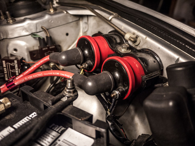
I removed the hacked-in lead I was pulling for the RPM switches and tapped them directly in at the ECU harness plug, and grounded the rpm switches back to the same ECU ground. I now have a solid RPM signal - before the RPM signal was jumping all over the place, i must have been creating a mad ground loop through the chassis.
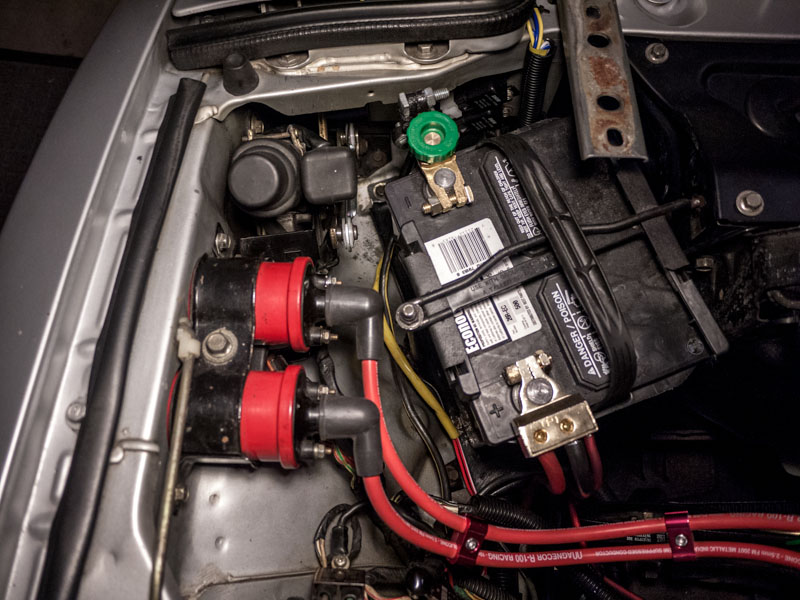
I am now calling the engine bay "done" for the time being. I have a few more ideas to clean it up a bit, and the driver's side still needs more love (and fresh paint, the battery acid seems to have had a go at it in a few spots), but overall i'm quite happy with how its looking.
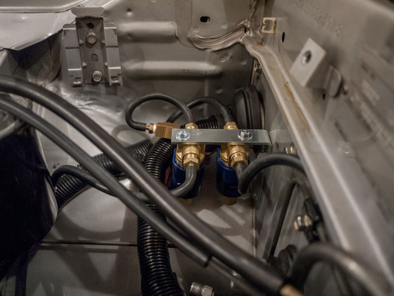
I replaced the OEM 25 year old pressure solenoids for the 6port and VDI system with some $30 ebay specials. these are high quality units, brass valves and tubing, can handle up to 120psi, no need to worry about blowing or wearing them out. The exhaust vent is on the bottom of the blue plastic part.

Another angle of the rpm switch harness (left), haltech harness (center), and CO2 6port/VDI solenoid system.
I made sure to crimp all connections securely, used bulb grease on all the connectors and grounds. Grounded all ECU-connected components to the exact same spot.
Re-routed almost all custom wires, a-pillar gauge leads, made sure the audio system is completely isolated from the ECU systems.
The RPM signal leads were looking quite sad, one of them completely snapped off its solder connection. Cleaned those up and did some fresh shrink wrap over top
I removed the hacked-in lead I was pulling for the RPM switches and tapped them directly in at the ECU harness plug, and grounded the rpm switches back to the same ECU ground. I now have a solid RPM signal - before the RPM signal was jumping all over the place, i must have been creating a mad ground loop through the chassis.
I am now calling the engine bay "done" for the time being. I have a few more ideas to clean it up a bit, and the driver's side still needs more love (and fresh paint, the battery acid seems to have had a go at it in a few spots), but overall i'm quite happy with how its looking.
I replaced the OEM 25 year old pressure solenoids for the 6port and VDI system with some $30 ebay specials. these are high quality units, brass valves and tubing, can handle up to 120psi, no need to worry about blowing or wearing them out. The exhaust vent is on the bottom of the blue plastic part.
Another angle of the rpm switch harness (left), haltech harness (center), and CO2 6port/VDI solenoid system.
Ready or not...
Joined: Dec 2009
Posts: 261
Likes: 0
From: Taos, NM
I got the Altitude adjustment part and can't get a wrench on the old one... appears as though I might have to remove the carb? If that's so, I have a whole pig pile of task to add to that! It will take a concerted session and as she has been functioning well as my daily driver....
I finally got from tank FULL to tank FULL with a trip odometer to find my current mpg to be 17.
I have been enjoying finding her RELIABLE! Still Winter comes and I need to get started on a heater.
I finally got from tank FULL to tank FULL with a trip odometer to find my current mpg to be 17.
I have been enjoying finding her RELIABLE! Still Winter comes and I need to get started on a heater.
Ready or not...
Joined: Dec 2009
Posts: 261
Likes: 0
From: Taos, NM
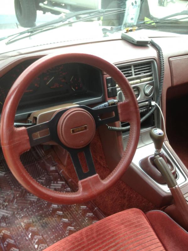
Thanks, it IS remarkably bad isn't it? I HAVE a little carpet thingy... came with the car. I just didn't appreciate it enough to get some double sided tape to keep it in place... I want a whole new dash... but no parts car in a 100 mi. radius (that I KNOW of YET)...
Joined: Jun 2008
Posts: 8,376
Likes: 30
From: Chino Hills, CA
I installed my relpacement battery, moved the car out into the sunlight, and made a list of things to do before JCCS this Saturday.
Thankfully, it's a short list. No time for major car projects these days.
Thankfully, it's a short list. No time for major car projects these days.
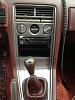
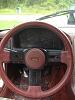
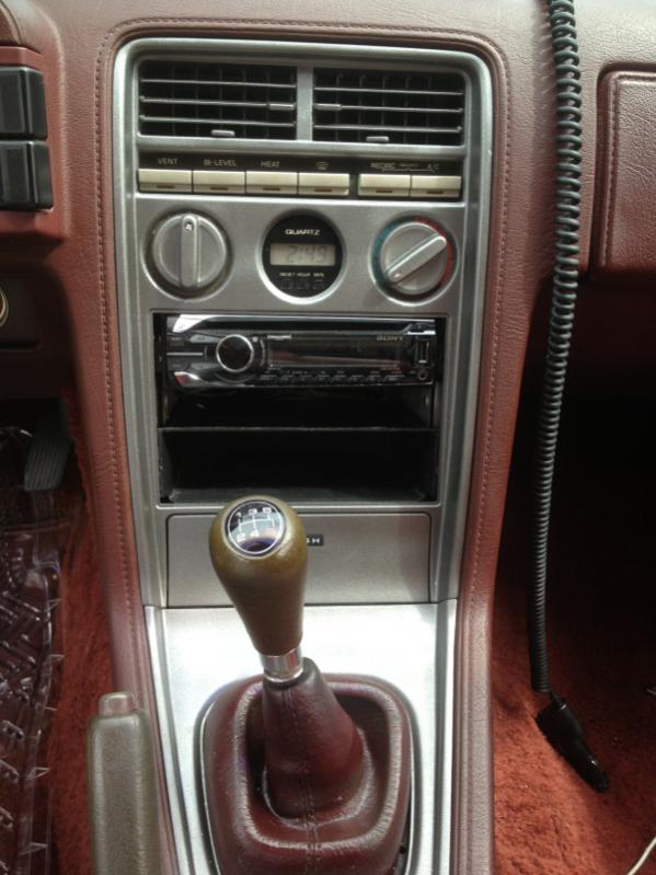
Finally have the interior back to all stock. Replaced the boot and shift ****, painted the radio surround and snagged an oem steering wheel off if eBay for 25.00 and it is mint. Now what to do with that ugly radio hole.


GSL-EV
Joined: Jun 2012
Posts: 450
Likes: 8
From: Rapid City, SD
I am glad she is starting to be reliable enough to drive daily. What are you missing that the heater doesn't work. I am sorry but I have destroyed my spare heater core else I would give it to you if that is what you need.
GSL-EV
Joined: Jun 2012
Posts: 450
Likes: 8
From: Rapid City, SD
I think there are still dash caps available. If you can't get a decent dash what you could do is strip off the vinyl and then smooth out any imperfections with something like a flexible filler. Silicone rubber might work although something that could be sanded would be better. Then apply a wet layup of fiberglass (or carbon fiber if you like that look.) Paint to match the interior. That would be 20 to 30 hours of work but would look pretty good when you got done although far from period correct. Best wishes finding a decent dash. Try advertising for what you need in the for sale section.
Last edited by dougingraham; Sep 25, 2013 at 03:11 PM.
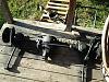
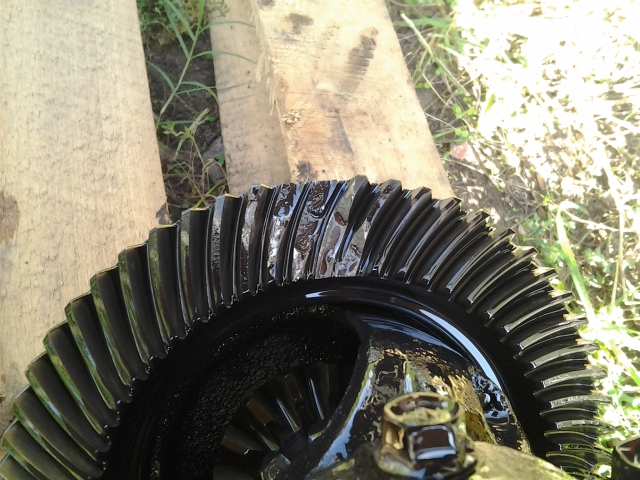
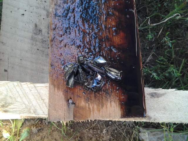
Took out and apart the rear-end and found this


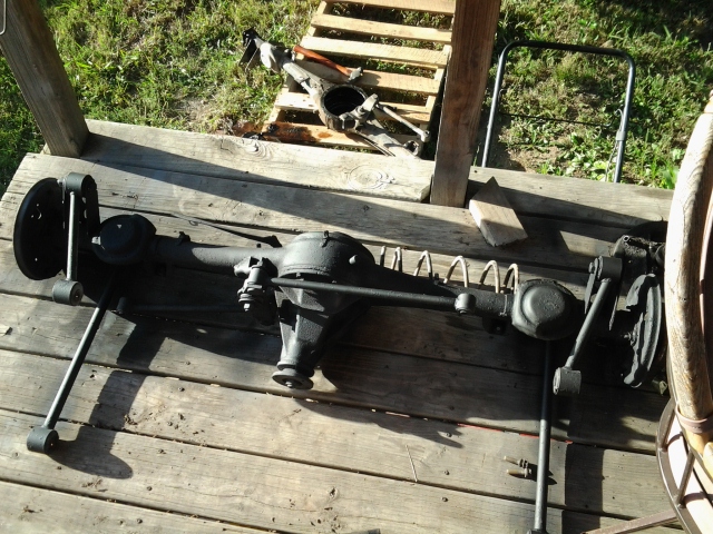
This is going in soon, needs one more coat of paint and the brake lines and wheel cylinders on.
Sent using RX7Club for Android.
This is going in soon, needs one more coat of paint and the brake lines and wheel cylinders on.
Sent using RX7Club for Android.
I shortened a pair of rear muffler hangers by 5mm to match my other ones. I don't know why they were so long on the SE, but they caused the mufflers I've tested in it to be too low, thus when I fab a system under it, then swapped to another car, the tail pipe hits the valance panel. Not anymore.


Joined: Jun 2006
Posts: 4,815
Likes: 24
From: Columbia, Tennessee
I shortened a pair of rear muffler hangers by 5mm to match my other ones. I don't know why they were so long on the SE, but they caused the mufflers I've tested in it to be too low, thus when I fab a system under it, then swapped to another car, the tail pipe hits the valance panel. Not anymore.
