
LED Custom Tail Light Idea W/Pics - Help Appreciated

Thread Starter
Joined: Aug 2011
Posts: 3,078
Likes: 42
From: Cambridge, Minnesota
Hey guys, thanks for checking my thread out. I would much appreciate any help, tips, or hints you could give me would be awesome. Please read through my ideas and goals, and let me know what you think!
I've been looking for a while now and have yet to find any custom tail lights for an FB. I have an 84 GS RX7, and being young, I would like to make some custom LED tail lights for my car. I love the way LED lights look, operate, and the safety and reliability they offer.
Here is a picture of my FB, the way it looks right now (picture was taken in August but it still looks the same).

I would love to do an LED board inside each of the 3 housings (reverse light, tail/brake light, and turn signal from inside to outside of the overall casing).
So I want to run a an LED board in the turn signal housing that would only light up when I turn on the blinker, which is pretty easily done. I will also run a LED board in the reverse light housing that would only light up when the car is in reverse (duh), which is still easily done.
The issue I am having is the tail light/brake light. To make the LEDs light up when my marker/running lights are on seems easy enough. But to make the LEDs light up brighter when I step on the brakes seems like a big issue. I have read up on this issue and may have a way to do it.
If we can figure this out i might consider building sets of these for other FB owners on here, if anyone else would be interested!!!
Here are a few pics for reference, I DO NOT CLAIM TO OWN ANY OF THESE IMAGES, RIGHTS ARE TO THE OWNER'S, LINK TO PICS UNDERNEATH EACH.
FC LED Conversion

http://speedhunters.com/archive/2010...vancouver.aspx
Audi A6 LED Conversion (Picked this because it's square and looks similar to what I'd like the finished product in my FB to look like)

http://www.audizine.com/forum/showth...ghts-for-C5-A6
I've been looking for a while now and have yet to find any custom tail lights for an FB. I have an 84 GS RX7, and being young, I would like to make some custom LED tail lights for my car. I love the way LED lights look, operate, and the safety and reliability they offer.
Here is a picture of my FB, the way it looks right now (picture was taken in August but it still looks the same).
I would love to do an LED board inside each of the 3 housings (reverse light, tail/brake light, and turn signal from inside to outside of the overall casing).
So I want to run a an LED board in the turn signal housing that would only light up when I turn on the blinker, which is pretty easily done. I will also run a LED board in the reverse light housing that would only light up when the car is in reverse (duh), which is still easily done.
The issue I am having is the tail light/brake light. To make the LEDs light up when my marker/running lights are on seems easy enough. But to make the LEDs light up brighter when I step on the brakes seems like a big issue. I have read up on this issue and may have a way to do it.
If we can figure this out i might consider building sets of these for other FB owners on here, if anyone else would be interested!!!
Here are a few pics for reference, I DO NOT CLAIM TO OWN ANY OF THESE IMAGES, RIGHTS ARE TO THE OWNER'S, LINK TO PICS UNDERNEATH EACH.
FC LED Conversion
http://speedhunters.com/archive/2010...vancouver.aspx
Audi A6 LED Conversion (Picked this because it's square and looks similar to what I'd like the finished product in my FB to look like)
http://www.audizine.com/forum/showth...ghts-for-C5-A6
Thread Starter
Joined: Aug 2011
Posts: 3,078
Likes: 42
From: Cambridge, Minnesota
Hey Jhreg, I have seen that mod done before but it won't light up brighter, which isn't as safe in my mind and I don't want my car rear ended. If it is my last resort I will go with this option, so good suggestion.
Directfreak, I am going to look into that, because the main concept that I am using seems to be able to figure out the dilemma, so he must be using 2 stage LEDs.
Heres the link http://www.bmw2002faq.com/component/...4a51c6cb29bb1/
Directfreak, I am going to look into that, because the main concept that I am using seems to be able to figure out the dilemma, so he must be using 2 stage LEDs.
Heres the link http://www.bmw2002faq.com/component/...4a51c6cb29bb1/
Thread Starter
Joined: Aug 2011
Posts: 3,078
Likes: 42
From: Cambridge, Minnesota
I'm not much help when it comes to electrical stuff, but if you do these right I may be interested in buying a set.
The only way that it will work is removing the diffusers from the tail lights.
I'll hopefully be taking apart either my tail light or getting a junk set from a junk yard to practice with.
Trending Topics
What if you just had one row of leds across the bottom for running lights, and have several rows above it for brake lights. Another idea would be face the bottom row upward shining into the housing so they wont appear as bright. I believe that's how the Cadillac STS's tail lights are set up, except they run up and down and the running lights face inward.
Joined: Jun 2008
Posts: 8,376
Likes: 28
From: Chino Hills, CA
Some basics:
The brightness of an LED (or a bunch of em) is controlled by the current thru the LED.
This current is controlled by a resistor placed in series with the LED. That's different than with traditional incandescent bulbs, where the bulb filament works as its own current-limiting resistor.
If you put too much current thru an LED, it will burn out, so all LED's have a current-limiting resistor used with them. The exact value is determined by the LEDs specs and the maximum voltage used.
The trick to making the LEDs brighter when stepping on the brake, is to have the brake pedal switch provide for more current thru the LED (without burning it up).
If you look at the marker-brake light circuit for an FB, you can see that the original design used a two-filament bulb; a dim 8-watt one that's on whenever the marker lights are on, and a brighter 27 watt one that gets power only when you step on the brake pedal.
The trick you're trying to pull off is made more complicated by it being the positive side that's switched, instead of the ground side, but basically what you need is a circuit that operates the LEDs at a lower current when the marker lights are on, but increases that current when the switch is stepped on. This can be done with a couple diodes, and some carefully chosen resistor values. The exact values will depend on the type and number of LEDs you'll use in each 'lamp assembly,' and you'll have to determine the brightness desired.
You also have to be sure on an FB that the current used is enough to keep the 'stop light checker' happy, or else you'll get a warning light on the dash every time you step on the brakes.
Not impossible, but some electronics theory knowledge & a little experimentation would be required to do it right.
Thread Starter
Joined: Aug 2011
Posts: 3,078
Likes: 42
From: Cambridge, Minnesota
What if you just had one row of leds across the bottom for running lights, and have several rows above it for brake lights. Another idea would be face the bottom row upward shining into the housing so they wont appear as bright. I believe that's how the Cadillac STS's tail lights are set up, except they run up and down and the running lights face inward.
Some basics:
The brightness of an LED (or a bunch of em) is controlled by the current thru the LED.
This current is controlled by a resistor placed in series with the LED. That's different than with traditional incandescent bulbs, where the bulb filament works as its own current-limiting resistor.
If you put too much current thru an LED, it will burn out, so all LED's have a current-limiting resistor used with them. The exact value is determined by the LEDs specs and the maximum voltage used.
The trick to making the LEDs brighter when stepping on the brake, is to have the brake pedal switch provide for more current thru the LED (without burning it up).
If you look at the marker-brake light circuit for an FB, you can see that the original design used a two-filament bulb; a dim 8-watt one that's on whenever the marker lights are on, and a brighter 27 watt one that gets power only when you step on the brake pedal.
The trick you're trying to pull off is made more complicated by it being the positive side that's switched, instead of the ground side, but basically what you need is a circuit that operates the LEDs at a lower current when the marker lights are on, but increases that current when the switch is stepped on. This can be done with a couple diodes, and some carefully chosen resistor values. The exact values will depend on the type and number of LEDs you'll use in each 'lamp assembly,' and you'll have to determine the brightness desired.
You also have to be sure on an FB that the current used is enough to keep the 'stop light checker' happy, or else you'll get a warning light on the dash every time you step on the brakes.
Not impossible, but some electronics theory knowledge & a little experimentation would be required to do it right.
The brightness of an LED (or a bunch of em) is controlled by the current thru the LED.
This current is controlled by a resistor placed in series with the LED. That's different than with traditional incandescent bulbs, where the bulb filament works as its own current-limiting resistor.
If you put too much current thru an LED, it will burn out, so all LED's have a current-limiting resistor used with them. The exact value is determined by the LEDs specs and the maximum voltage used.
The trick to making the LEDs brighter when stepping on the brake, is to have the brake pedal switch provide for more current thru the LED (without burning it up).
If you look at the marker-brake light circuit for an FB, you can see that the original design used a two-filament bulb; a dim 8-watt one that's on whenever the marker lights are on, and a brighter 27 watt one that gets power only when you step on the brake pedal.
The trick you're trying to pull off is made more complicated by it being the positive side that's switched, instead of the ground side, but basically what you need is a circuit that operates the LEDs at a lower current when the marker lights are on, but increases that current when the switch is stepped on. This can be done with a couple diodes, and some carefully chosen resistor values. The exact values will depend on the type and number of LEDs you'll use in each 'lamp assembly,' and you'll have to determine the brightness desired.
You also have to be sure on an FB that the current used is enough to keep the 'stop light checker' happy, or else you'll get a warning light on the dash every time you step on the brakes.
Not impossible, but some electronics theory knowledge & a little experimentation would be required to do it right.
I will also having a computer tech helping me with this project, and he has been working with LEDs for years now. So I will be showing him this thread and everything you guys have said and I will post up our work as money/time/work hours allow.
Thanks to all again!
Thread Starter
Joined: Aug 2011
Posts: 3,078
Likes: 42
From: Cambridge, Minnesota
Hey Chris!
The turn signals are going to come second, after the marker lights. The two yellow front marker lights and the rear two red marker lights will be my first area to conquer.
We'll see how that goes, I will post the progress up here as soon as I can!
The turn signals are going to come second, after the marker lights. The two yellow front marker lights and the rear two red marker lights will be my first area to conquer.
We'll see how that goes, I will post the progress up here as soon as I can!
its supposed to do that
Joined: Jan 2003
Posts: 1,352
Likes: 2
From: PNW
What you want is high brightness LEds with a PWM controller to lower the pulse width for the running light state.
http://www.rcaz.com/images/electroni...ive/instr4.pdf
A guy on hid-planet make the opti-drive ones and they are some of the best around.
Isaac
http://www.rcaz.com/images/electroni...ive/instr4.pdf
A guy on hid-planet make the opti-drive ones and they are some of the best around.
Isaac


You could have one ring of LEDs for running lights and another (brighter) for brakes lights. Use a controller and power the controller via relays driven off the current lighting circuit. This way if you ever wanted to go back stock the wiring isn't all hacked up. Also, the LEDs would not be perfoming double duty.
http://www.superbrightleds.com/cgi-b...rake-turn.html
work smart, not hard.
Motorcycles put those in their tail lights. I'd get a few of the round ones and try to replicate that FC
work smart, not hard.
Motorcycles put those in their tail lights. I'd get a few of the round ones and try to replicate that FC
I have seen something similar to these at work that we use on service vehicles http://www.ebay.com/itm/24V-LED-REAR...item19cc3405bf
Thread Starter
Joined: Aug 2011
Posts: 3,078
Likes: 42
From: Cambridge, Minnesota
What you want is high brightness LEds with a PWM controller to lower the pulse width for the running light state. http://www.rcaz.com/images/electroni...ive/instr4.pdf A guy on hid-planet make the opti-drive ones and they are some of the best around.
Isaac
Isaac
I checked out your reference and it�s another awesome idea! I would need to follow any written instructions that come with the purchase of a controller. Again, I will have an experienced LED builder on my side so together we should be able to figure it out. I actually took the reference you put here into my build list on my computer, so thanks again!

Austin
You could have one ring of LEDs for running lights and another (brighter) for brakes lights. Use a controller and power the controller via relays driven off the current lighting circuit. This way if you ever wanted to go back stock the wiring isn't all hacked up. Also, the LEDs would not be perfoming double duty.
http://www.superbrightleds.com/cgi-b...rake-turn.html work smart, not hard. Motorcycles put those in their tail lights. I'd get a few of the round ones and try to replicate that FC

I have seen something similar to these at work that we use on service vehicles http://www.ebay.com/itm/24V-LED-REAR...item19cc3405bf

Heres an option I was considering on trying at one point. Instead of outlining the curve like Dan did, I was going to do either rotors or circles.
http://www.oznium.com/forum/topic231...light-led+tail
http://www.oznium.com/forum/topic231...light-led+tail
Thread Starter
Joined: Aug 2011
Posts: 3,078
Likes: 42
From: Cambridge, Minnesota
Rotors would be awesome!!! Now I really want to figure out how to do that Chris! I hope it would be ok if I used that idea because that sounds like it could be awesome! The credit will be entirely yours, I will not take someone else's idea without proper credit, they call that plagiarism where I'm from and that's baaaaaaaad news.
Update guys, I need some more rotary help. Here are some pictures of FB tail lights (not my pictures). I was down visiting my FB in storage and noticed that there are 4 bulbs.... for 3 housings.... 2 in the center housing which is the place I've been having the issue with figuring out the LEDs. In case that didn't make sense, there is a running light and a brake light (if I am correct, please adjust me if I'm wrong).
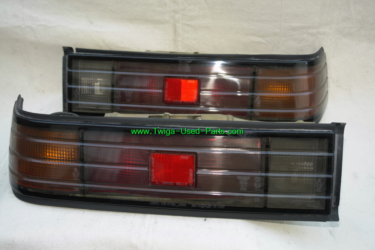
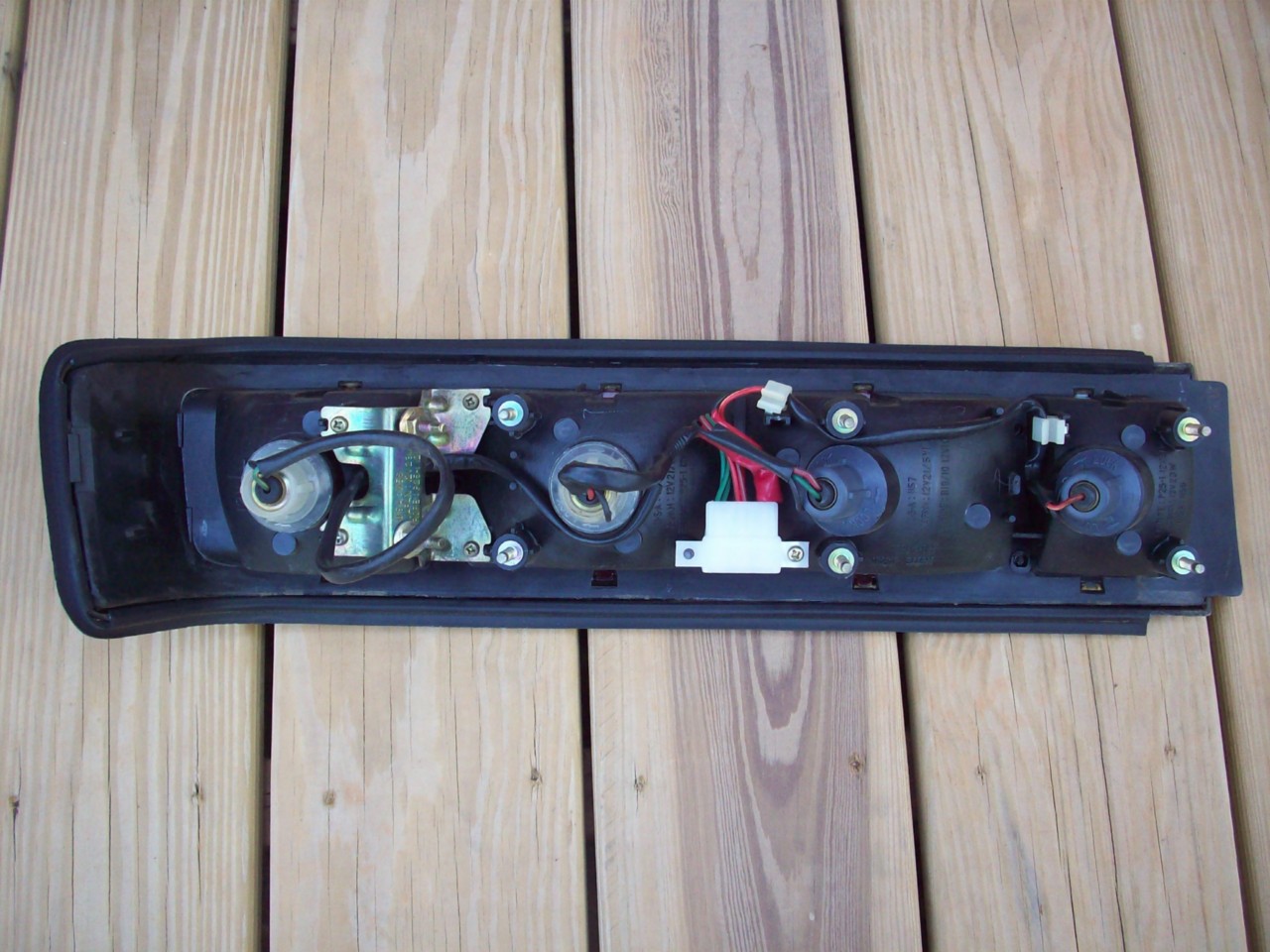
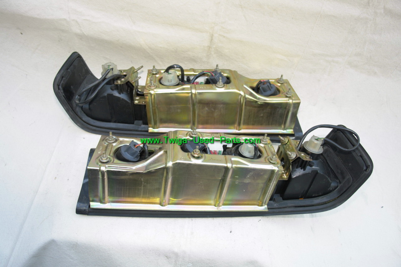
THESE IMAGES ARE FROM SELLERS CURRENTLY ON EBAY, I DO NOT CLAIM THE RIGHTS TO THE PICTURES, I GOT THEM FROM A SIMPLE EBAY SEARCH
So new idea, credit to Chris, is making a formation with two rotors per tail light for running lights, and when I step on the brakes, having the entire tail light light up. So people behind me would be seeing two rotors in each tail light and a bar of LEDs when I step on the brake. It sounds awesome and I'll draw up a sketch for us all to look at and critique.
Update guys, I need some more rotary help. Here are some pictures of FB tail lights (not my pictures). I was down visiting my FB in storage and noticed that there are 4 bulbs.... for 3 housings.... 2 in the center housing which is the place I've been having the issue with figuring out the LEDs. In case that didn't make sense, there is a running light and a brake light (if I am correct, please adjust me if I'm wrong).
THESE IMAGES ARE FROM SELLERS CURRENTLY ON EBAY, I DO NOT CLAIM THE RIGHTS TO THE PICTURES, I GOT THEM FROM A SIMPLE EBAY SEARCH
So new idea, credit to Chris, is making a formation with two rotors per tail light for running lights, and when I step on the brakes, having the entire tail light light up. So people behind me would be seeing two rotors in each tail light and a bar of LEDs when I step on the brake. It sounds awesome and I'll draw up a sketch for us all to look at and critique.
Thread Starter
Joined: Aug 2011
Posts: 3,078
Likes: 42
From: Cambridge, Minnesota
Real fast idea using paint with the rotary running light idea. Got the image from Polak Graphics for the rotary and the I Rotor My RX-7 is a sticker of theirs.
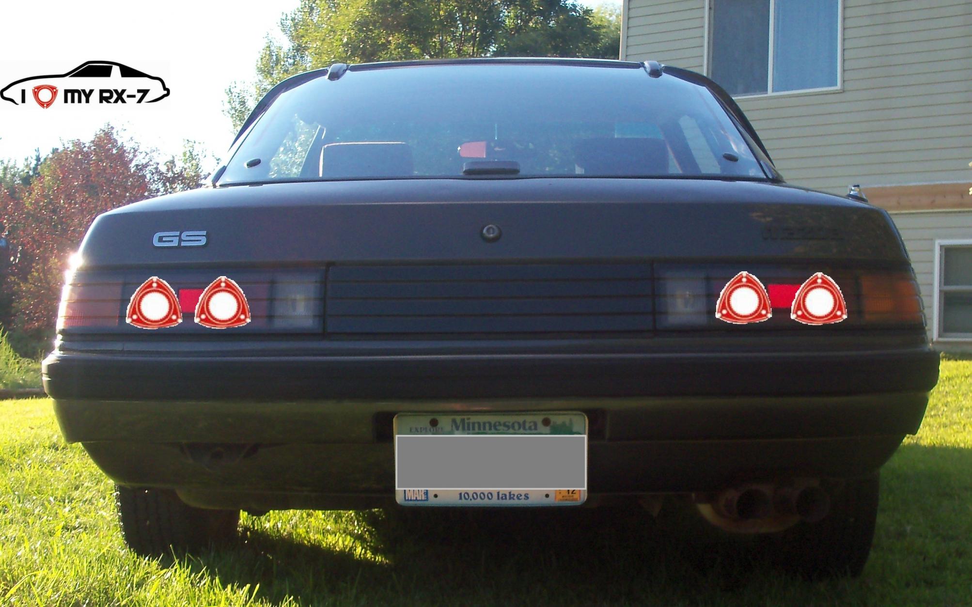
Again, really crappy 5 minute paint job but it gets the point across. Would this not be awesome???
Again, really crappy 5 minute paint job but it gets the point across. Would this not be awesome???


