Grounding How To - Thorough and Discriptive
 06-24-03, 10:44 PM
#1
Daily Domestic Killer
Thread Starter
Join Date: Mar 2001
Location: San Antonio, Tx, USA
Posts: 2,425
Likes: 0
Received 0 Likes
on
0 Posts
<moderator edit/note>
Please note... any modifications done to the electrical system should be first tested with a multi-meter, to confirm you are on the right wires.
Wire colors sometimes change based on year, so do not consider any wire color listed as gospel, and check it before doing anything.
If you blow your car up or damage anything or cause a fire, it will be your's and only your fault for not testing correctly.
<end moderators edit/note>
Due to request from my last post to be more thorough and descriptive on this grounding issue - here goes and I'm going to try and fit this all in one post.
Now to begin the Tools you will need to under go this project are as follows:
1. 5' of 10 gauge wire
2. 5-10' of 4-8 gauge battery wires with ring connectors
3. Plenty of Electrical Tape
4. Plenty of Rosin Core Solder
5. A Good quality soldering Iron
6. A box of insulated ring connectors
7. Pair of Wire Strippers and crimpers
8. A multimeter that has volt measurements
Most of these are a necessity for a home toolbox, if you do not own any of these things they can be found at a local auto parts store and or Radio Shack.
Just like always before working on any part of you car disconnect the negative battery cable. Now to get to work. The wires and parts that are being grounded are:
1. Leading Coil
2. Trailing Coil
3. On cars made before Nov 86 (checking the ground at boost sensor)- Not for cars made November 86 and later
4. Fuel Injector Harness (Engine Harness)
5. Emissions Control Unit
Now in my previous post I added grounding the alternator but I don't think that is necessary since its grounded to the water pump housing ect.
1. The Leading coil - it was mentioned in my previous post that it is not necessary to ground the coils because they are already grounded to the chassis, this is true but what this also does is add another chassis ground to the battery as well as making the Ignition system grounding bullet proof. For this application I used 2 insulated ring connectors crimped to about a 6" 10 gauge wire. One side connects to the negative battery cable; the other connects to a bolt on the Leading coil.

2. The Trailing coil - the purpose is pretty much the same as the leading, although this time I used about 8-10" of 10 gauge wire crimped with 2 ring connectors. One of the ring connectors is bolted to the factory chassis battery ground shown in the picture, the other side is bolted to the trailing coil bracket where the condenser (little black box thingy) is bolted to. (not shown in the pic)

3. On pre Nov 86 cars:
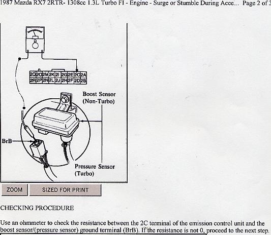
If resistance is higher than 0 ohms, then run a ground wire from the Brown/black on the boost sensor to one of the bolts on the water filler neck on the engine. This is a factory TSB for pre November 86 production cars, and not recommended for any later models.
4. Fuel Injection Harness - This harness is under the UIM and it holds the wires for the fuel injectors, TPS, and intake temp sensor, there is also a ring connector that comes out of the harness that is grounded to the top of the engine, this ring connector is copper so over time it will develop green oxidation that results in a poor connection, on my 88 TII is was bolted on one of the bolts that holds on the vacuum rac on (or used too :p ).
Sorry but I didn't have time to pull my UIM to take a pic of this wire, but I will take a pic soon if requested. Once you have found this ring connector its time to add a ground wire, I used a 15" 8 gauge wire that I got from Pettit racing for free. Connect one side to the factory chassis ground (same ground that you connected the trailing coil to) and connect the other side to the bolt that holds the fuel injector harness ground ring connector down (make sure you clean that ground from the green oxidation) and bolt down that ground and the 8 gauge wire with the same bolt, thus adding more ground to the fuel injection harness.

This is where I had it grounded before, still can't see the harness ground but it may help

5. Emissions Control Unit - Last but defiantly not least, the ECU ground, this ground is most often over looked because it seems difficult but actually its quit easy. Again I use the 10 gauge wire about 12" this time crimped 1 ring connector on one side and striped the other side about 2 cm. Now to find the ECU ground wire, it�s pretty easy to find looking at this schematic remember you are looking at the rear of the plugs in this pic.

Once you find this ground wire you should also test it with a multimeter to make sure you have the right wire. Then cut it and strip each side 2 cm. Tightly twist the 2 sides of the ecu ground to the 10 gauge wire and get you solder and soldering iron and start soldering (more is better ) Then of course wrap it tightly with electrical tape. I bolted the other side to the firewall where the ECU guard (big metal thing) bolts to the firewall...... in the the pic.

Well there is it Folks as thorough as it gets, and if anyone has better pics of the grounding I will be glad to host them. I'll try and get some more pics of the Fuel injection harness ground this week.
Please note... any modifications done to the electrical system should be first tested with a multi-meter, to confirm you are on the right wires.
Wire colors sometimes change based on year, so do not consider any wire color listed as gospel, and check it before doing anything.
If you blow your car up or damage anything or cause a fire, it will be your's and only your fault for not testing correctly.
<end moderators edit/note>
Due to request from my last post to be more thorough and descriptive on this grounding issue - here goes and I'm going to try and fit this all in one post.
Now to begin the Tools you will need to under go this project are as follows:
1. 5' of 10 gauge wire
2. 5-10' of 4-8 gauge battery wires with ring connectors
3. Plenty of Electrical Tape
4. Plenty of Rosin Core Solder
5. A Good quality soldering Iron
6. A box of insulated ring connectors
7. Pair of Wire Strippers and crimpers
8. A multimeter that has volt measurements
Most of these are a necessity for a home toolbox, if you do not own any of these things they can be found at a local auto parts store and or Radio Shack.
Just like always before working on any part of you car disconnect the negative battery cable. Now to get to work. The wires and parts that are being grounded are:
1. Leading Coil
2. Trailing Coil
3. On cars made before Nov 86 (checking the ground at boost sensor)- Not for cars made November 86 and later
4. Fuel Injector Harness (Engine Harness)
5. Emissions Control Unit
Now in my previous post I added grounding the alternator but I don't think that is necessary since its grounded to the water pump housing ect.
1. The Leading coil - it was mentioned in my previous post that it is not necessary to ground the coils because they are already grounded to the chassis, this is true but what this also does is add another chassis ground to the battery as well as making the Ignition system grounding bullet proof. For this application I used 2 insulated ring connectors crimped to about a 6" 10 gauge wire. One side connects to the negative battery cable; the other connects to a bolt on the Leading coil.
2. The Trailing coil - the purpose is pretty much the same as the leading, although this time I used about 8-10" of 10 gauge wire crimped with 2 ring connectors. One of the ring connectors is bolted to the factory chassis battery ground shown in the picture, the other side is bolted to the trailing coil bracket where the condenser (little black box thingy) is bolted to. (not shown in the pic)
3. On pre Nov 86 cars:
If resistance is higher than 0 ohms, then run a ground wire from the Brown/black on the boost sensor to one of the bolts on the water filler neck on the engine. This is a factory TSB for pre November 86 production cars, and not recommended for any later models.
4. Fuel Injection Harness - This harness is under the UIM and it holds the wires for the fuel injectors, TPS, and intake temp sensor, there is also a ring connector that comes out of the harness that is grounded to the top of the engine, this ring connector is copper so over time it will develop green oxidation that results in a poor connection, on my 88 TII is was bolted on one of the bolts that holds on the vacuum rac on (or used too :p ).
Sorry but I didn't have time to pull my UIM to take a pic of this wire, but I will take a pic soon if requested. Once you have found this ring connector its time to add a ground wire, I used a 15" 8 gauge wire that I got from Pettit racing for free. Connect one side to the factory chassis ground (same ground that you connected the trailing coil to) and connect the other side to the bolt that holds the fuel injector harness ground ring connector down (make sure you clean that ground from the green oxidation) and bolt down that ground and the 8 gauge wire with the same bolt, thus adding more ground to the fuel injection harness.
This is where I had it grounded before, still can't see the harness ground but it may help
5. Emissions Control Unit - Last but defiantly not least, the ECU ground, this ground is most often over looked because it seems difficult but actually its quit easy. Again I use the 10 gauge wire about 12" this time crimped 1 ring connector on one side and striped the other side about 2 cm. Now to find the ECU ground wire, it�s pretty easy to find looking at this schematic remember you are looking at the rear of the plugs in this pic.
Once you find this ground wire you should also test it with a multimeter to make sure you have the right wire. Then cut it and strip each side 2 cm. Tightly twist the 2 sides of the ecu ground to the 10 gauge wire and get you solder and soldering iron and start soldering (more is better
) Then of course wrap it tightly with electrical tape. I bolted the other side to the firewall where the ECU guard (big metal thing) bolts to the firewall...... in the the pic. Well there is it Folks as thorough as it gets, and if anyone has better pics of the grounding I will be glad to host them. I'll try and get some more pics of the Fuel injection harness ground this week.
Last edited by Icemark; 05-23-05 at 10:44 AM.
 06-24-03, 11:46 PM
#2
Senior Member
Join Date: Jul 2001
Location: Parma, MI
Posts: 412
Likes: 0
Received 0 Likes
on
0 Posts
Question on the ECU ground. I've got an AFC2 untill I go Haltech and you are supposed to add one wire to the ground near the ecu and the other on the wire but back farther and not to the chassis or too close together or it will harm the ecu or afc. Is it safe to ground the ecu wire with this or not? Maybe the other end of it? (wherever that is)
06-25-03, 01:38 AM
#3
Rotary Enthusiast

Join Date: Jan 2003
Location: fl
Posts: 1,255
Likes: 0
Received 0 Likes
on
0 Posts
what is all this grounding for, i'v heard of bigger main grounding straps but to me at least grounding every individual component seems like overkill. does every part realy need its own ground to the chasis?
06-25-03, 02:00 PM
#5
rawr
iTrader: (2)
Join Date: Feb 2001
Location: Silver City, NM
Posts: 2,331
Likes: 0
Received 0 Likes
on
0 Posts
if you ground pin 2C on the ECU it takes care of the boost sensor, and a lot of other things also. just a note, might make the boost sensor thing easier
Edit: You should ground 2C, 2R, 3A and 3G. If you look at the EGI AND EMISSIONS CONTROL SYSTEM diagram, you see that the brown wire with a black stripe(86-87 models) Pin 2C is the ground for the tps, boost sensor, variable resistor, water thermo sensor, atmospheric sensor, afm sensor, etc. That is why it is a good idea to add a ground to that pin 2C wire
Edit: You should ground 2C, 2R, 3A and 3G. If you look at the EGI AND EMISSIONS CONTROL SYSTEM diagram, you see that the brown wire with a black stripe(86-87 models) Pin 2C is the ground for the tps, boost sensor, variable resistor, water thermo sensor, atmospheric sensor, afm sensor, etc. That is why it is a good idea to add a ground to that pin 2C wire
Last edited by Agent_D; 06-25-03 at 02:08 PM.
06-25-03, 06:14 PM
#6
I'm a boost creep...
Join Date: Jan 2002
Location: Auckland, New Zealand
Posts: 15,608
Likes: 0
Received 8 Likes
on
8 Posts
You shouldn't just add a new ground wire to one of the ECU's earth wires. It has four of them and they should all be dealt with.
If you strip away some of the insulation tape you'll find that all of the ECU's earth wires are joined together onto one big wire only 6" or so from the ECU. This join is not a particularly good one and I've heard it's prone to failure.
The best way to reground the ECU is to desolder this join and solder it all back together properly with both the stock main ground wire and another new ground wire, and bolt the new wire to the body nearby.
06-25-03, 06:48 PM
#7
What Subscription?
Join Date: Apr 2001
Location: Aiken SC USA
Posts: 5,926
Likes: 0
Received 0 Likes
on
0 Posts
Good Point NZ, however I have seen extreme difficulty with soldering on the existing harness. I have tried precleaning with Acetone, alchohol and still have trouble getting the existing ground wire to "take" solder. I have a new cleaner on the way I am experimenting with
Trending Topics
06-25-03, 09:19 PM
#8
Daily Domestic Killer
Thread Starter
Join Date: Mar 2001
Location: San Antonio, Tx, USA
Posts: 2,425
Likes: 0
Received 0 Likes
on
0 Posts
Yeah when installing the ecu ground wire I posted above it was really hard to get the solder to stick to the ecu wires, I had to use a bunch.
takerwolf, I'm not totaly sure about your question, do you mean your APEXi SAFC 2? If so I'll check on that later tonight..
takerwolf, I'm not totaly sure about your question, do you mean your APEXi SAFC 2? If so I'll check on that later tonight..
06-25-03, 09:52 PM
#9
I'm a boost creep...
Join Date: Jan 2002
Location: Auckland, New Zealand
Posts: 15,608
Likes: 0
Received 8 Likes
on
8 Posts
Originally posted by takerwolf
I've got an AFC2 untill I go Haltech and you are supposed to add one wire to the ground near the ecu and the other on the wire but back farther and not to the chassis or too close together or it will harm the ecu or afc. Is it safe to ground the ecu wire with this or not?
I've got an AFC2 untill I go Haltech and you are supposed to add one wire to the ground near the ecu and the other on the wire but back farther and not to the chassis or too close together or it will harm the ecu or afc. Is it safe to ground the ecu wire with this or not?
I don't know why this is so important, but they seem very adament about it.
 06-25-03, 10:14 PM
#10
Jesus is the Messiah
I belive this is somewhat related:
(I have an FC3C) I was going about running the ground straps, and I noticed the stock negitive battery wire has corroded internally to a simply unacceptable level. I decided to replace it and tried to trace it out . . . no such luck, goes into a series of electrical-taped conduits. I checked the manuals but cant find anything even resembling a wiring diagram for that (Its probably right under my nose).
Where does the negitive terminal lead?
06-25-03, 11:44 PM
#11
I'm a boost creep...
Join Date: Jan 2002
Location: Auckland, New Zealand
Posts: 15,608
Likes: 0
Received 8 Likes
on
8 Posts
Read this thread.
06-26-03, 09:23 PM
#15
Daily Domestic Killer
Thread Starter
Join Date: Mar 2001
Location: San Antonio, Tx, USA
Posts: 2,425
Likes: 0
Received 0 Likes
on
0 Posts
Thanks for the help answering questions Jason, I've been workin crazy hours this last week.....Well if you call siting on your *** and watchin the honeys "work" , Lifegaurding is the best job to have  , hopefully I'll get to be on here more next week.....
, hopefully I'll get to be on here more next week.....
06-27-03, 08:34 PM
#17
Daily Domestic Killer
Thread Starter
Join Date: Mar 2001
Location: San Antonio, Tx, USA
Posts: 2,425
Likes: 0
Received 0 Likes
on
0 Posts
On my next day off I'll get pics of the injector harness grounds and give instructions on adding a power wire from the battery to the alternator
06-30-03, 02:32 PM
#18
Rotary Enthusiast
Originally posted by Tofuball
I belive this is somewhat related:
(I have an FC3C) I was going about running the ground straps, and I noticed the stock negitive battery wire has corroded internally to a simply unacceptable level. I decided to replace it and tried to trace it out . . . no such luck, goes into a series of electrical-taped conduits. I checked the manuals but cant find anything even resembling a wiring diagram for that (Its probably right under my nose).
Where does the negitive terminal lead?
Hot_Dog
90 RX7 GXL
02 Acura RSX-S
 07-01-03, 12:55 PM
#21
Senior Member
Join Date: Apr 2003
Location: Reno, NV
Posts: 290
Likes: 0
Received 0 Likes
on
0 Posts
Just like always before working on any part of you car disconnect the negative battery cable. Now to get to work. The wires and parts that are being grounded are:
07-01-03, 01:46 PM
#22
Daily Domestic Killer
Thread Starter
Join Date: Mar 2001
Location: San Antonio, Tx, USA
Posts: 2,425
Likes: 0
Received 0 Likes
on
0 Posts
Sorry to sound like such a noob... but what is the point of all this if everything already works? I dont get it.
Also, how come you wanna disconenct the negative battery cable before you do any maintenence?
07-01-03, 01:59 PM
#23
Daily Domestic Killer
Thread Starter
Join Date: Mar 2001
Location: San Antonio, Tx, USA
Posts: 2,425
Likes: 0
Received 0 Likes
on
0 Posts
is there a good way to get at the main ground on the starter? i just tried and could not get a good view/angle at it
07-02-03, 12:40 AM
#25
I'm a boost creep...
Join Date: Jan 2002
Location: Auckland, New Zealand
Posts: 15,608
Likes: 0
Received 8 Likes
on
8 Posts
Originally posted by BlackRx7
...basically it starts at the negative battery terminal then goes to the side of the firewall ground...
...basically it starts at the negative battery terminal then goes to the side of the firewall ground...
Last edited by NZConvertible; 07-02-03 at 12:42 AM.