
Megasquirt Official RX7 Megasquirt FAQ for MS1 (check here before you ask your question)

Thread Starter
MegaSquirt Mod
Joined: Sep 2004
Posts: 4,721
Likes: 1
From: Maryland
Official RX7 Megasquirt FAQ for MS1 (check here before you ask your question)
Alright, I'm going to post as much info as I can think of here having to do with the megasquirt on a rotary engine, each question in a post. Before asking a question in the megasquirt section, please check this thread to see if your question has already been answered.
First question, and the one that seems to be the most popular:
1) There are so many different options for megasquirt, what do I need?
Options:
There are currently 3 options available for the megasquirt board: v2.2, v3, and v3.57 (SMT)
The v3 board's advantages over the 2.2 board can be found here:
http://www.megamanual.com/ms2/pcb.htm
The v3.57 board is not DIY, but surface-mount instead, and requires less modification to use.
You can use any version of the board to run a rotary. I recommend the v3/v3.57 board if you have the money, but if not, you can get the 2.2 board, and it'll work just fine.
The next thing you need in each case is the ciruitry to handle conditioning the signal from the CAS. (2nd gen).
For the V2.2 board, you'll need a dual lm1815 circuit. For this, I recommend error*'s board, which also includes circuitry for several of the other features that msns-extra supports, such as EGT logging, table switching, water injection, launch control, nitrous control, boost control, and extra outputs (good for actuating VDI, aux ports, etc...)
For the V3/v3.57 board, you actually already have a single vr sensor conditioner, so you have 2 choices: cut two opposing teeth out of the CAS, and use only the single built-in vr sensor conditioner, or build a second vr sensor conditioner (lm1815 works)... you can do that in the v3 board's proto area, or you can just get error*'s, or jbperf's daughterboard, and only build/use one of the lm1815 circuits on there. It is recommended to use the second VR setup as that is less prone to noise.
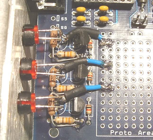
For the v2.2 and v3 boards, you will need to install 1 4.7K pull-up resistor from the negative lead of each of the LED's to a +5v source:
If you plan on using the stock air temperature sensor, you'll also need to replace the bias resistor for air temperature with a resistor between 30k and 50k. On the v2.2 and v3 board you'll replace R4.
If you plan on controlling your BAC valve on a v2.2 board, you'll want to get a ztx688 or ztx689 transistor, and replace Q5 with it. Also, you'll want to get a 1/2 watt 510 ohm resistor, and replace R16 with it. You can also get a TIP12x transistor and wire that to the transistor through holes for the original Q5. The v3.57 board has a transistor built-in that can handle enough current, so no mods are necessary to use that.
I don't think anyone has done any testing on a v3 board to make it control a BAC valve, but I believe you'd want to change out Q4 with the ztx688 or ztx689, and change out R19 with a 1/2 watt 510 ohm resistor. You can also replace Q4 with a TIP12x transistor, which some have found is more robust than the ztx parts.
There are also 2 options for the megasquirt chip. There are the MS1 chip and the MS2 chip.
Finally, you'll need to wire the megasquirt up to your car. I'll post info on that in a later post.
EDIT, some false info updated. Pics will be re-added as I find or take some.
EDIT2: This FAQ covers items specific to MS1, I'll be adding another FAQ for MS2
Ken
First question, and the one that seems to be the most popular:
1) There are so many different options for megasquirt, what do I need?
Options:
There are currently 3 options available for the megasquirt board: v2.2, v3, and v3.57 (SMT)
The v3 board's advantages over the 2.2 board can be found here:
http://www.megamanual.com/ms2/pcb.htm
The v3.57 board is not DIY, but surface-mount instead, and requires less modification to use.
You can use any version of the board to run a rotary. I recommend the v3/v3.57 board if you have the money, but if not, you can get the 2.2 board, and it'll work just fine.
The next thing you need in each case is the ciruitry to handle conditioning the signal from the CAS. (2nd gen).
For the V2.2 board, you'll need a dual lm1815 circuit. For this, I recommend error*'s board, which also includes circuitry for several of the other features that msns-extra supports, such as EGT logging, table switching, water injection, launch control, nitrous control, boost control, and extra outputs (good for actuating VDI, aux ports, etc...)
For the V3/v3.57 board, you actually already have a single vr sensor conditioner, so you have 2 choices: cut two opposing teeth out of the CAS, and use only the single built-in vr sensor conditioner, or build a second vr sensor conditioner (lm1815 works)... you can do that in the v3 board's proto area, or you can just get error*'s, or jbperf's daughterboard, and only build/use one of the lm1815 circuits on there. It is recommended to use the second VR setup as that is less prone to noise.
For the v2.2 and v3 boards, you will need to install 1 4.7K pull-up resistor from the negative lead of each of the LED's to a +5v source:
If you plan on using the stock air temperature sensor, you'll also need to replace the bias resistor for air temperature with a resistor between 30k and 50k. On the v2.2 and v3 board you'll replace R4.
If you plan on controlling your BAC valve on a v2.2 board, you'll want to get a ztx688 or ztx689 transistor, and replace Q5 with it. Also, you'll want to get a 1/2 watt 510 ohm resistor, and replace R16 with it. You can also get a TIP12x transistor and wire that to the transistor through holes for the original Q5. The v3.57 board has a transistor built-in that can handle enough current, so no mods are necessary to use that.
I don't think anyone has done any testing on a v3 board to make it control a BAC valve, but I believe you'd want to change out Q4 with the ztx688 or ztx689, and change out R19 with a 1/2 watt 510 ohm resistor. You can also replace Q4 with a TIP12x transistor, which some have found is more robust than the ztx parts.
There are also 2 options for the megasquirt chip. There are the MS1 chip and the MS2 chip.
Finally, you'll need to wire the megasquirt up to your car. I'll post info on that in a later post.
EDIT, some false info updated. Pics will be re-added as I find or take some.
EDIT2: This FAQ covers items specific to MS1, I'll be adding another FAQ for MS2
Ken
Last edited by muythaibxr; Feb 3, 2009 at 07:30 PM. Reason: Update
Thread Starter
MegaSquirt Mod
Joined: Sep 2004
Posts: 4,721
Likes: 1
From: Maryland
OK, next item in the FAQ:
how to wire the dual lm1815 vr sensor conditioner to the megasquirt, and the rest of what to do to get signals to the ignitors.
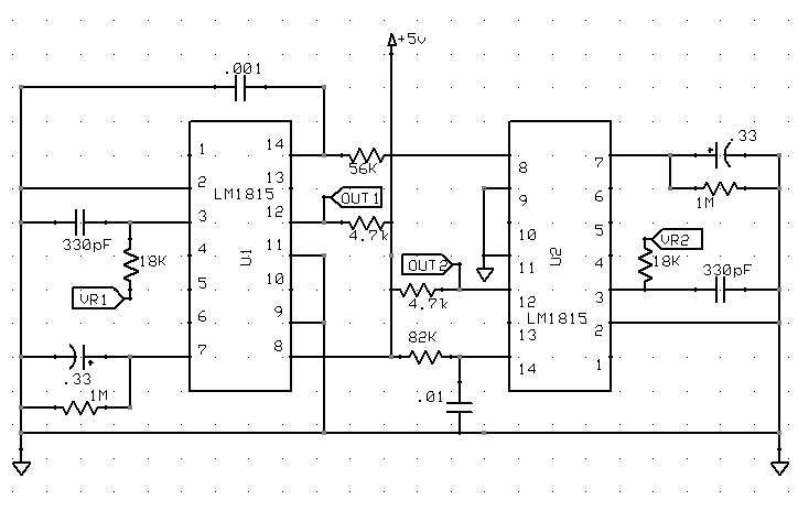
For the dual lm1815 circuit, I have no pictures or diagrams of how to wire it, aside from the picture that was posted earlier in another thread of the dual lm1815 circuit. This is the circuit that comes on error*'s daughtercard (thanks to renns and Rex4Life for the diagram):

If you're using a dual lm1815 setup with a v2.2 board, remember to replace the 56k resistor with a 39k resistor, and replace the .001 uF cap with a .01uF cap.
(these instructions are for a v2.2 board)
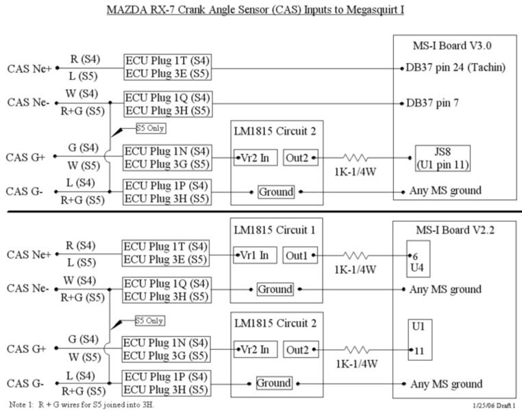
Basically, VR1 should be wired to the Ne+ wire on the CAS (24 tooth VR sensor positive lead). That VR sensor's ground should be grounded to the lm1815 board you use). VR2 should be wired to the G+ wire leaving the CAS (2 tooth VR sensor positive lead). It's ground should also run to the lm1815 board.
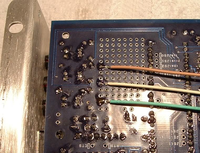
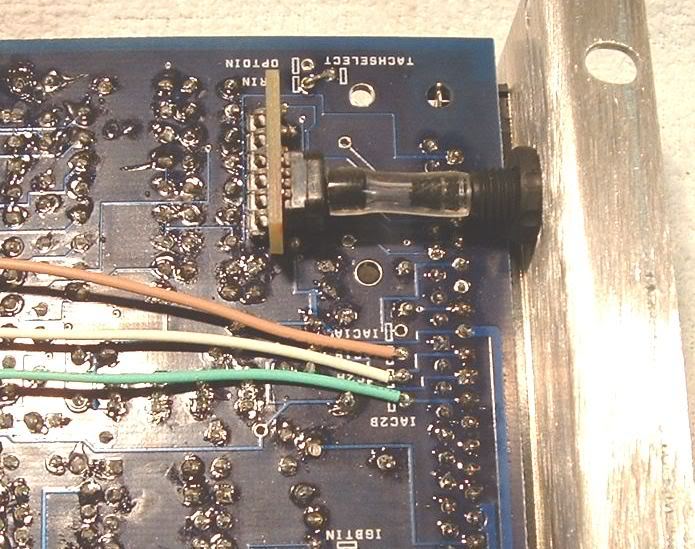
OUT1 should be wired to pin 6 of U4 on the megasquirt board. U4 is a six pin chip... also known as the opto-isolator. OUT2 should be wired through a 1k resistor to pin 11 on the CPU.
(these are for the v3 board)
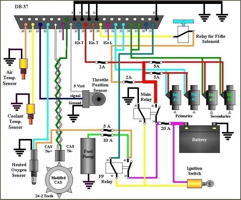
On the v3 board, things are a bit different. You'll want to create the right side of the above schematic in the proto area, or use just the top part of the dual lm1815 circuit on error*'s msns-extra board. This circuit will be used for the G+/G- signal. For the 24 tooth circuit, you can use the built-in vr sensor conditioner. For that, just wire Ne+ to pin 24 on the DB37 connector, and wire Ne- to pin 7.
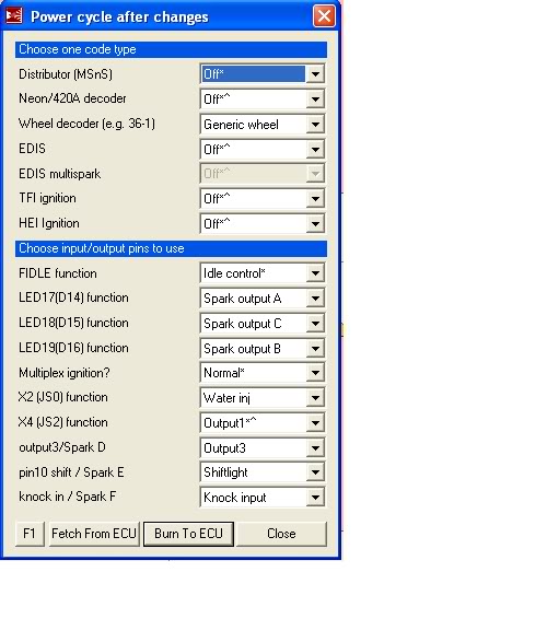
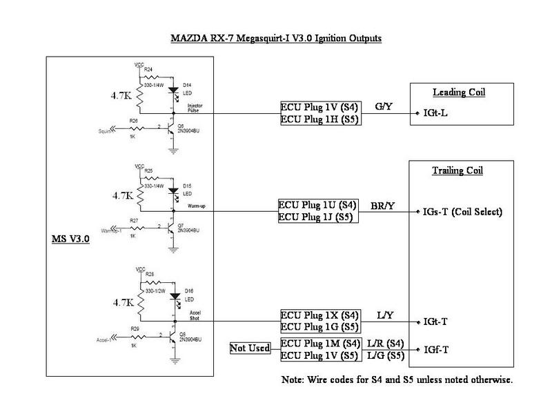
For both the v3 and v2.2 board, you'll want to put the 4.7Kohm resistors as detailed in my last post, and then you'll want to wire the negative lead of led 17 (the one closest to the serial port) to your leading ignitor's IGt wire (IGt-L). The negative lead of led 18 goes to the coil select wire on your trailing ignitor (IGs-T). Finally, the negative lead of led 19 will need to be wired to the IGt wire on the trailing ignitor (IGt-T).
That's it! As far as I can remember, those are all the hardware mods necessary to run the stock 2nd gen ignition.
how to wire the dual lm1815 vr sensor conditioner to the megasquirt, and the rest of what to do to get signals to the ignitors.
For the dual lm1815 circuit, I have no pictures or diagrams of how to wire it, aside from the picture that was posted earlier in another thread of the dual lm1815 circuit. This is the circuit that comes on error*'s daughtercard (thanks to renns and Rex4Life for the diagram):
If you're using a dual lm1815 setup with a v2.2 board, remember to replace the 56k resistor with a 39k resistor, and replace the .001 uF cap with a .01uF cap.
(these instructions are for a v2.2 board)
Basically, VR1 should be wired to the Ne+ wire on the CAS (24 tooth VR sensor positive lead). That VR sensor's ground should be grounded to the lm1815 board you use). VR2 should be wired to the G+ wire leaving the CAS (2 tooth VR sensor positive lead). It's ground should also run to the lm1815 board.
OUT1 should be wired to pin 6 of U4 on the megasquirt board. U4 is a six pin chip... also known as the opto-isolator. OUT2 should be wired through a 1k resistor to pin 11 on the CPU.
(these are for the v3 board)
On the v3 board, things are a bit different. You'll want to create the right side of the above schematic in the proto area, or use just the top part of the dual lm1815 circuit on error*'s msns-extra board. This circuit will be used for the G+/G- signal. For the 24 tooth circuit, you can use the built-in vr sensor conditioner. For that, just wire Ne+ to pin 24 on the DB37 connector, and wire Ne- to pin 7.
For both the v3 and v2.2 board, you'll want to put the 4.7Kohm resistors as detailed in my last post, and then you'll want to wire the negative lead of led 17 (the one closest to the serial port) to your leading ignitor's IGt wire (IGt-L). The negative lead of led 18 goes to the coil select wire on your trailing ignitor (IGs-T). Finally, the negative lead of led 19 will need to be wired to the IGt wire on the trailing ignitor (IGt-T).
That's it! As far as I can remember, those are all the hardware mods necessary to run the stock 2nd gen ignition.
Last edited by muythaibxr; Feb 3, 2009 at 07:35 PM.


Thread Starter
MegaSquirt Mod
Joined: Sep 2004
Posts: 4,721
Likes: 1
From: Maryland
As "The Griffin" suggested, I'm posting this here.
From my testing, I have found that it is necessary to leave the LED's in to get the stock 2nd gen ignitors to work properly.
I think it's just because the LED's pull the current away from the ignitors completely when it's time to fire the coils, where leaving the led's out, the transistor can't pull all the current away from the ignitors, causing them not to fire the coils.
This is just my speculation as far as the reason why the LED's need to be in there go, but according to my testing, all of my megasquirts failed to fire the coils when the LED's were out, and all fired the coils just fine with the LED's in.
Thread Starter
MegaSquirt Mod
Joined: Sep 2004
Posts: 4,721
Likes: 1
From: Maryland
For those who are having trouble getting the megasquirt to start their car due to no rpms in megatune, usually configuration is the issue, but if the configuration is correct, then the next most likely culprit is electrical system, specifically the grounds. Aaron Cake has a very good article on the RX7 grounds here: http://www.aaroncake.net/rx-7/grounding.htm
I suggest reading that and following his instructions as they are the best I've seen for grounding problems.
I suggest reading that and following his instructions as they are the best I've seen for grounding problems.

Trending Topics

2 LM1815 VR conditioner circuits for 13B rotary
Can someone please confirm the VR circuit diagram posted by twister?
The circuit at: http://www.msextra.com/manuals/MS_Ex...m#rotaryengine
also appears to be incorrect.
From twister's diagram, should:
- 56k resistor replaced with 39K
- .001uF capacitor be changed to .01uF
- 18K resistors for both VR input lines (Vin-pin3)?
- 1k (MS CPU current spike protection) resistor(s) as specified in the CAS inputs to
Megasquirt diagram for the outputs Out1/Out2 (REF-pin12)?
Thanks
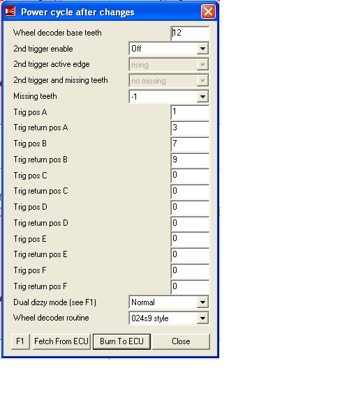
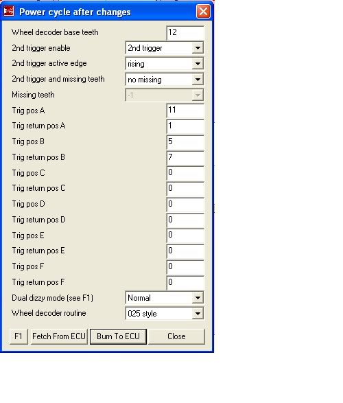
I've found this forum quite helpful for a lot of things. Maybe the lounge doesnt give helpful love-life advice, but for technical stuff I've always had luck. Good job twister, my one comment would be to comment on which of the wheel decoder settings is for the ground-off cas, and which is for the stock cas with LM1815N circuit (and drop the 11-1-5-7 settings, since I think most people are running 1-3-7-9 now, and it seems to be the preferred way.)

Thread
Thread Starter
Forum
Replies
Last Post
ncds_fc
New Member RX-7 Technical
1
Aug 15, 2015 10:06 AM