
4-Rotor FC Build


Joined: Mar 2001
Posts: 31,863
Likes: 3,245
From: https://www2.mazda.com/en/100th/
Higgi and i were talking yesterday, and he reminded me that the haltechs fire the ignition when you turn the key on, and usually it just backfires, but i've seen the engine turn about 1/2 a rotation...

Thread Starter
Joined: Oct 2010
Posts: 605
Likes: 13
From: The Netherlands
Dry sump is the way ahead =) I would be really scared to cavicate the stock oilpump spinning it so fast and feeding it with hot aerated oil. all it takes is a second with no oil to weld the bearing to the shaft.
What helps is enough clearance, good balancing, good synthetic oil and DLC coating on the shaft. We ran with the 2 rotor 13B 45 min with every right hand corner less than 0.3 bar oil (light went on) at over 8k rpm WOT. opened up the engine to find no damage at all.. what we did notice was accelerated wear on the side housings, we guess it comes due to the rotor wobbeleing on the shaft. after we fixed the oil issues with dry sump we opened the engine up again after each race for a variaty of silly reasons. the wear remained constant after each race afterwards.
I heard from other builders that at these rpm anything less than a few bar of oil would kill the stationary bearing real soon, at least they ran old tech SAE oil and no DLC coating ..
For clearance we run 0.13mm on the main bearings. tapered them .2mm towards the end as described the old competitoon manual.. did a few pulls to 10k5 rpm with no ill effects so far.
As for oil pump stuff, you are kindoff right, BUT I haven't ran the car on the track yet, and the engine hasn't been to high rpm's yet. It's been to 7000 rpms a few times very briefly, but most of the time it was under 3500, so I don't think it's the issue.
I also used the competition manual as a reference, and I did set up the bearing clearance at 0.13mm. To get the required clearance I removed material from the bearing. I actually found that once enough material was removed from the bearing that the grey looking stuff (that's babbit right?) was gone, and only copper was left. I was a little worried about it, but after asking around a bit it seemed to be common, so I put it in. I disassembled the engine to a shortblock today, and looked at both the front and rear main bearings, this is how they looks:


The e-shaft is looking ok from what I can tell, but it looks like the copper material of the bearing is flaking off. I'm not 100% sure why yet... I'll disassemble the short block later this week, Fingers crossed the damage isn't too extensive!
Exhaust Manifold Leak

Joined: Jun 2005
Posts: 815
Likes: 42
From: western europe
Auch.. If oil was not the problem it can only be bent shaft (very unlikely as I am quite certain you checked this before assembly), or a very out of balance rotating assembly. But still at these low rpm this should not be a problem at all. Even if the middle bearing would be not inline with the outer then I would guess the damage would be situated at one side of the bearing..
I grinded the shaft to get the .13mm clearance. Didnt want to remove the babbit. Are there signs on the shaft of intereference with the bearing? On our engine after the 45 min race with low oil press at the front rotor bearing there was a small strip where the babbit had started to stick to the shaft surface. The area on thr bearing felt a bit like the peel of an orange. Im rely certain the dlc saved our *** (rotors) as the bearing where not locked in the rotors apart from the stock lip
I grinded the shaft to get the .13mm clearance. Didnt want to remove the babbit. Are there signs on the shaft of intereference with the bearing? On our engine after the 45 min race with low oil press at the front rotor bearing there was a small strip where the babbit had started to stick to the shaft surface. The area on thr bearing felt a bit like the peel of an orange. Im rely certain the dlc saved our *** (rotors) as the bearing where not locked in the rotors apart from the stock lip
Joined: Mar 2001
Posts: 31,863
Likes: 3,245
From: https://www2.mazda.com/en/100th/
good thing you're catching it now!

Rotary Freak
Joined: Aug 2012
Posts: 2,886
Likes: 411
From: MELBOURNE AUSTRALIA
I all ways use old bearings [Used ones ] in all my race motors if possible , stops this problem ,New bearings are too soft and tend to pick up to easy, The used bearings have a hard glazing on surface and need very little running in . New bearings need around 1- 2000 klm to run in.
Linishing down bearings till copper is showing is a disaster waiting to happen
Linishing down bearings till copper is showing is a disaster waiting to happen
Wasted spark plug
Joined: May 2012
Posts: 64
Likes: 0
From: Enschede, The Netherlands
Is there a relationship between the point of the oil injection on the main shaft and the position of the rotor when it's being fired?
Maybe the oil film is broken (although you run 6bars, right?) as it looks like serious grinding to me...
This has nothing to do with "running in".
I do really hope you find the answer(s) as this build is awsome, even the aftermath!
Grtz Dee.
Maybe the oil film is broken (although you run 6bars, right?) as it looks like serious grinding to me...
This has nothing to do with "running in".
I do really hope you find the answer(s) as this build is awsome, even the aftermath!
Grtz Dee.
Last edited by Black and Blue RX; Sep 17, 2014 at 07:18 AM. Reason: poor english
Thread Starter
Joined: Oct 2010
Posts: 605
Likes: 13
From: The Netherlands
So, I disassembled the engine tonight, and well the good part is that the rotor housings, rotors, seals and irons all look just fine. Unfortunately it pretty much ends there. All the main bearings, and all the rotor bearings are trash!
This is a picture of the rotor bearing, all 4 bearings look similar. It's worn down to the point where even the copper is gone:

And this is the center bearing:

And this is what the eccentric shaft looks like:
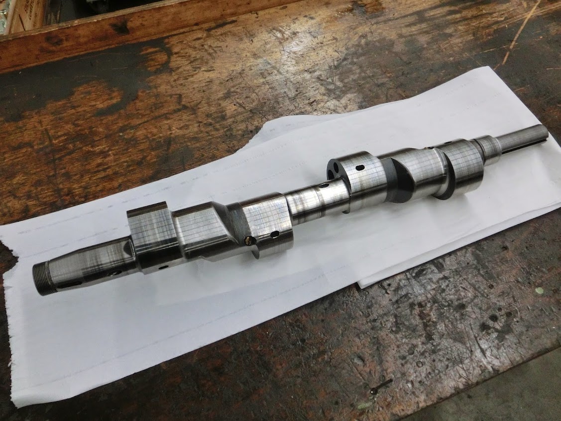
One point of interest though is the middle of the shaft. Notice that discoloured part there? Here is a close-up:

I had a facepalm moment when I saw the shaft. It's not that difficult to figure out what happened here. To clairify just look at this picture here:

It's a section view of an eccentric shaft in a main bearing. On the right is how I currently have it, with 2 grooves (Look at the first picture of this post if you don't get it). On the left is how every other engine has it. The problem here is that usually oil goes into the groove, gets pressed in between the bearing and the shaft, and then flows outwards. However, with my bearing the oil comes in through 2 grooves, and part of the oil can flow outwards, but the oil between the 2 grooves gets trapped with nowhere to go. Because it can't go anywhere the oil that gets in there stays there, and that's where it gets dangerous. A bearing like this has friction which generates heat. The oil that flows through a bearing carries away that heat. Since this does not happen with my bearing it get's hot, ergo the discolouring. There looks to be a dark grey colour. Steel turns blue at 300deg C, and dark grey at 430deg C, so yeah, things got a bit toasty in there.
So, what to do from here... I�m not completely sure yet. But these are the things that in my opninion are currently wrong about my setup:
- The 2 grooves in my center bearing
- The linishing of my main and rotor bearings was probably a bad idea, I think WJM rotaries is right about that one. I should grind the shaft a bit smaller and use normal bearings
- The wet overdriven oil system I currently have probably isn't that good.
- Oil temperature probably also can be better, I've seen 150deg C (300deg F) which is too much.
So I dunno, maybe try to fix all of the above things and have another go at it?
This is a picture of the rotor bearing, all 4 bearings look similar. It's worn down to the point where even the copper is gone:
And this is the center bearing:
And this is what the eccentric shaft looks like:
One point of interest though is the middle of the shaft. Notice that discoloured part there? Here is a close-up:
I had a facepalm moment when I saw the shaft. It's not that difficult to figure out what happened here. To clairify just look at this picture here:
It's a section view of an eccentric shaft in a main bearing. On the right is how I currently have it, with 2 grooves (Look at the first picture of this post if you don't get it). On the left is how every other engine has it. The problem here is that usually oil goes into the groove, gets pressed in between the bearing and the shaft, and then flows outwards. However, with my bearing the oil comes in through 2 grooves, and part of the oil can flow outwards, but the oil between the 2 grooves gets trapped with nowhere to go. Because it can't go anywhere the oil that gets in there stays there, and that's where it gets dangerous. A bearing like this has friction which generates heat. The oil that flows through a bearing carries away that heat. Since this does not happen with my bearing it get's hot, ergo the discolouring. There looks to be a dark grey colour. Steel turns blue at 300deg C, and dark grey at 430deg C, so yeah, things got a bit toasty in there.
So, what to do from here... I�m not completely sure yet. But these are the things that in my opninion are currently wrong about my setup:
- The 2 grooves in my center bearing
- The linishing of my main and rotor bearings was probably a bad idea, I think WJM rotaries is right about that one. I should grind the shaft a bit smaller and use normal bearings
- The wet overdriven oil system I currently have probably isn't that good.
- Oil temperature probably also can be better, I've seen 150deg C (300deg F) which is too much.
So I dunno, maybe try to fix all of the above things and have another go at it?
Exhaust Manifold Leak
Joined: Jun 2005
Posts: 815
Likes: 42
From: western europe
Your logic makes sense, but even when the center bearing was a bit of a misdesign with the 2 grooves, why do all the other bearings look like this? I would expect fron the center bearing to fail but the others should be fine as long as they receive enough fresh/clean oil
Rotary Freak
Joined: Aug 2012
Posts: 2,886
Likes: 411
From: MELBOURNE AUSTRALIA
2- oil temperature too high
3- oil pressure to high and volume too low
4- too much bearing clearance
5- detonation
Thread Starter
Joined: Oct 2010
Posts: 605
Likes: 13
From: The Netherlands
Sure, here you go:


I don't think that the rotors have hit the rotor housings if that's what your looking for. I did side and face clearance the rotors a little bit, which is where the texture comes from.
I agree with points 1, 2, and 4 on your list. I probably should have done some things a little bit differently. But I don't really see how you can have too much pressure and too little oil flow? I used a non-modified 13B-REW regulator in the rear, with the normal FC regulator in the front shimmed out 1/8". Oil pressure is 110psi, drops to about 45psi at idle when hot. I'm also sure that the engine did not detonate, I haven't ran with more than 18 degrees of timing, so that's overly conservative, and I haven't heard any knock (I have knock detection earphones with a bosch sensor bolted to one of the rotor housings).
Exhaust Manifold Leak
Joined: Jun 2005
Posts: 815
Likes: 42
From: western europe
If oil temp is too high, it will boil and cavitate the pump, this will lead to smell of burnt oil and offcourse drop in oil pressure. John said the oilpressure was steady 110 psi at high rpm, which is more than plenty for a NA engine spinning only 7krpm for short bursts. Also too much bearing clearance is never a problem in a journal bearing design as long as the oil flow is sufficient to built the required pressure. No engine ever failed from running too much clearance (in a reasonable amount offcourse) as long as the oil pressure remains up. detonation is also very unlikelely on a NA engine. and even then it would be noticeable on the porcelain of the plugs and the tooth of the stat gear long before it takes out every bearing in the engine.

I'm going to ask the stupid question: Could you have left dirt or grit in the oil passages of the crank and/or the galley ways of the engine? Dirty oil cooler? I know that the places that offer nitriding around here do it in sand and one really has to work to make sure all practicals are cleaned out. I've considered refinishing and re-nitriding some side plates but think the only way to get them free of the sand and its dust would be another hot tank dip or ultra sonic cleaning.
Rotary Freak
Joined: Aug 2012
Posts: 2,886
Likes: 411
From: MELBOURNE AUSTRALIA
Thanks John ,No signs of detonation on rotas . Your oil pressures are good .but volume could be too low. Your oil pump is designed to work on up to 3 rotas and 1 oil cooler not 4 rotas and 2 oil coolers. I still think is mainly the machining of the bearings is your main problem . Also what oil and grade are you using
If I were you I'd inspect the crap out of that eshaft: runouts for concentricity, cylindricity of all bearing surfaces, and rotor lobe eccentricity. Seems like you had some issues with the rough machining and grinding that you apparently solved, but the story of how you fixed it seems foggy. While you may have some oiling issues, they don't seem to be the root cause of the bearing failures. I hope you figure it out cause you certainly don't want to repeat this glitter anomaly.
Superb solidworks skills mate. Have you generated a dimensioned drawing of the shaft with feature control symbols? Seems worth it for such a critical item.
Superb solidworks skills mate. Have you generated a dimensioned drawing of the shaft with feature control symbols? Seems worth it for such a critical item.
"Elusive, not deceptive!�
Joined: May 2007
Posts: 930
Likes: 13
From: Slidell, LA
John-
Great build and machine work!
The damage really looks like oil starvation to me.
I like to do a couple of things to cut-down on "manufactured" oil pressure leaks.
Stone the face of the pump flange to make sure it is perfectly flat.
I use the thinnest tissue paper that I can find with 515 Loctite Gasket Eliminator.
It is an anaerobic flange sealant. Wipe off excess let it cure for 24 hrs.
Reestablish internal pump clearance to compensate for the extra gasket thickness.

Another overlooked area is the front and rear oil passage from the stationary gear-flange to side plate. (The excess sealant can be removed through passage center but this is not required.)

Also... porting the oil passages and putting a bellmouth on the pickup can help flow.

All the little oil mods you can do will help. I agree with and have done what Barry shows and more on my 2 rotor.
The latest thing I did was dowel pin the oil passage between the front side housing and front cover as high oil pressure kept pushing the front cover away from the housing and pushing the o-ring into the front cover. Now the o-ring is captured by the dowel inside it as well as having a leakage path greatly diminished by the press fit of the dowel.
Enough about me and my little 2 rotor-
Do you have two oil entries into the e-shaft 180 deg apart on each main bearing journal or just one.
You need to get a lot of oil into the e-shaft to feed the rotor journals and the rotor oil cooling jets.
Ok, one more thing about me- can't resist.
I do drill the rear e-shaft oil entry through on my old TII e-shafts to get more oil into the shaft as I run a loop line to the front main bearing so the oil pressure is more equal. No need to artificially equalize oil flow to the rear rotor bearing and rotor cooling jet by restricting the side that doesn't have the huge pressure drop of traveling the tortured path through the dowels like in the stock system. I also "tear drop" port the e-shaft oil holes for easier oil ingress and egress.
You say you have good oil pressure.
If you think about it, oil pressure is just an indication of the restriction to oil flow into the e-shaft. Once it is in the e-shaft its hard to measure oil pressure (its like 0- don't bother) and the rotor oil cooling jets are the recirculation/low pressure side for most all of the oil flow.
To recap- oil pressure in the rotary is just the measure of the pressure losses from the sides of the fed main bearings, and the restriction of the oil entering the e-shaft.
So, if flow was limited through the e-shaft you might expect your directly fed main bearings to look better as they should still get plenty of oil.
Perhaps if run for a very short duration. However, the heat put into the oil from low pressure on all the other bearing surfaces could have taken its toll even at the spots with adequate pressure.
*This is the same theory as you have with your center bearing stagnant oil overheating all the oil, but many times more heat put into the oil through more bearing area.*
150C is way too hot for oil to live in my eyes.
This must be the oil temp in the pan and not the temp at the feed to the bearings after the oil cooler? I do have my oil temp in the bearing oil supply and it rarely gets over 100C racing in a turbo car.
What size are your rotor oil cooling jets? Large stock ones with check ***** or the restricted Mazdacomp race ones that keep rotor bearings happier?
Anyways, I only hope that I have given you some new ways to view your oil system problems. I really want to see you get this bad *** project sorted out!
I do agree you could use an oil relief area between the center bearing journals
It could be as simple as a chamfer on the mating e-shaft journals along with small holes drilled radially through to a groove in the stat gear/bearing housing where the bearings meet up (and notches in the bearings sides if they are flush- which it does not look like).

Senior Member
Joined: Apr 2009
Posts: 311
Likes: 2
From: Lynchburg, VA
If you have issues finding the annarobic sealer. Go to your local vw dealer. Its green in color and is used for sealing the cam plate to the head on all ccta and bpy engines. If you still have issues with getting some, let me know, I will gladly mail you some from out of my toolbox as I have extra laying around.
Thread Starter
Joined: Oct 2010
Posts: 605
Likes: 13
From: The Netherlands
I'm going to ask the stupid question: Could you have left dirt or grit in the oil passages of the crank and/or the galley ways of the engine? Dirty oil cooler? I know that the places that offer nitriding around here do it in sand and one really has to work to make sure all practicals are cleaned out. I've considered refinishing and re-nitriding some side plates but think the only way to get them free of the sand and its dust would be another hot tank dip or ultra sonic cleaning.
Thanks John ,No signs of detonation on rotas . Your oil pressures are good .but volume could be too low. Your oil pump is designed to work on up to 3 rotas and 1 oil cooler not 4 rotas and 2 oil coolers. I still think is mainly the machining of the bearings is your main problem . Also what oil and grade are you using
If I were you I'd inspect the crap out of that eshaft: runouts for concentricity, cylindricity of all bearing surfaces, and rotor lobe eccentricity. Seems like you had some issues with the rough machining and grinding that you apparently solved, but the story of how you fixed it seems foggy. While you may have some oiling issues, they don't seem to be the root cause of the bearing failures. I hope you figure it out cause you certainly don't want to repeat this glitter anomaly.
Superb solidworks skills mate. Have you generated a dimensioned drawing of the shaft with feature control symbols? Seems worth it for such a critical item.
Superb solidworks skills mate. Have you generated a dimensioned drawing of the shaft with feature control symbols? Seems worth it for such a critical item.
John-
Great build and machine work!
The damage really looks like oil starvation to me.
I like to do a couple of things to cut-down on "manufactured" oil pressure leaks.
Stone the face of the pump flange to make sure it is perfectly flat.
I use the thinnest tissue paper that I can find with 515 Loctite Gasket Eliminator.
It is an anaerobic flange sealant. Wipe off excess let it cure for 24 hrs.
Reestablish internal pump clearance to compensate for the extra gasket thickness.
http://i287.photobucket.com/albums/l...4-2464_IMG.jpg
Another overlooked area is the front and rear oil passage from the stationary gear-flange to side plate. (The excess sealant can be removed through passage center but this is not required.)
http://i287.photobucket.com/albums/l...ps38712650.jpg
Also... porting the oil passages and putting a bellmouth on the pickup can help flow.
http://i287.photobucket.com/albums/l...ps5898d997.jpg
Will do so next time!
The dowel pin in the front cover is a good idea, I drilled and tapped the front iron, so the oil pump flow directly goes out the front plate, but I kept the output in the front cover aswell. This way I have 2 oil pressure outputs, that I plumbed into 2 coolers, so their mounted in parallel.
The oil is fed to the rotor bearing and cooling jet via a single hole, but it's reasonably large and teardrop shaped. But looking at it I guess I can drill the e-shaft so there are 2 entry holes like the oem shaft has. That's a good idea! The cooling jet is a fixed jet without ball and spring, I believe it's 1.5mm or so.
The 150deg oil temperature was measured after the coolers, but it was only once and very briefly, on our crappy dyno. It usually was around 95deg C, with water being 85deg C.
If you have issues finding the annarobic sealer. Go to your local vw dealer. Its green in color and is used for sealing the cam plate to the head on all ccta and bpy engines. If you still have issues with getting some, let me know, I will gladly mail you some from out of my toolbox as I have extra laying around.

So thanks for the reply's everyone, there are some good suggestions there. I'm still not sure what I'm going to do though, kindoff doubting between 3 options:
1. Fix the issue with the center bearing, increase some aspects of the oiling system like doweling the front cover, sealing the pump and stationairy gears, maybe add a few holes to the e-shaft. Clean up the e-shaft and grind the e-shaft a little bit smaller for bearing clearance. Maybe it's a good idea to use the same shaft diameters as the RX-8 uses, and use the same bearing clearance as the RX-8 does since I'm only turning about 8500 rpm. Then put everything together with new bearings, and try again while keeping a very very close eye to sings of bearing damage.
2. Fix the issue with the center bearing, but ditch the REW oil pump, and piece together a dry sump system with an appropriate pump that can handle the flow and pressure. A mazda competition kit is too expensive for me, so it would probably be either an external pump, or a lot of custom work and R&D to fabricate a front cover that incorporates a (probably 3-stage) pump. I think a good dry sump will help my engine a lot, and I hate my 2-piece oil pan so it would be nice to be able to throw that out. However, I can easily see me taking the entire winter to piece together a system like that, and I'm kindoff scared of trying an untested oiling system on my 4-rotor engine. There's always a chance of a new system to have some issues, especially with something that is pieced together on a budget.
3. Assembly the engine in 2-rotor form and get that up and running. I need to fabricate a new exhaust header for this, and a new intake manifold, but the rotor housings, rotors, injectors, ignition, ecu ect. will all be the same as used on the 4-rotor. With the engine running I can really spend some time getting the ecu tune dialed in perfect (Which I can then use as a really good starting point for the 4-rotor, because everything is the same, except the number of rotors). I can also spend time improving the chassis, and making sure that everything is working well and all the bugs are gone. When the car is running I can then work on the 4-rotor, fixing issues and building a dry sump setup. When I finally do come up with a dry sump system It might even be possible to test it out on the 2-rotor aswell.
It's not very glamourous, but it would be nice to drop the 4-rotor in a chassis where everything is tested and working well, with a good ecu tune right on the first start. Ah well, I don't know... Maybe I should man up, slap the 4-rotor together, throw it in, start it up and start doing insane burnouts

Rotary Freak
Joined: Aug 2012
Posts: 2,886
Likes: 411
From: MELBOURNE AUSTRALIA
John I use a 25- 70 mineral oil in all my rotaries , since going to this grade have never had any bearing related problems or oil pressure drop off . I don't know if available where u are but I use nothing but Penrite HPR40 that is a 25-70 is Australian made
I also found what I thought was an oil pan leak. It turned out the exhaust gaskets were leaking a lot, and because of all the raw fuel getting into the exhaust the guey stuff that leaks out of there looked a lot like oil. It was leaking because the homemade exhaust gasket did not work. My engine has wierd exhaust ports so the oem gaskets don't work, so I got some copper plate, and fitted some cutting rings into the exhaust flange to keep the copper from being pressed out.
There seems to be a pretty good seal between the exhaust flange and the copper, but it's very leaky between the copper and the engine, so not really a succes. The next best bet is probaby to just machine the exhaust flange flat and find some sort of gasket material that works. I already cobbled together a jig and machined it flat:
Hey John, I have an exhaust design similar to yours on my NA 20b. Instead of building a dedicated insert for the housing, I built my insert into the header flange itself and just eliminated the sleeve altogether. I don't have all of that nice machinery so it was my shade tree mechanic approach.
 I built this back in 2008 when I was doing all my fabrication. It's nothing pretty but it works with zero leaks
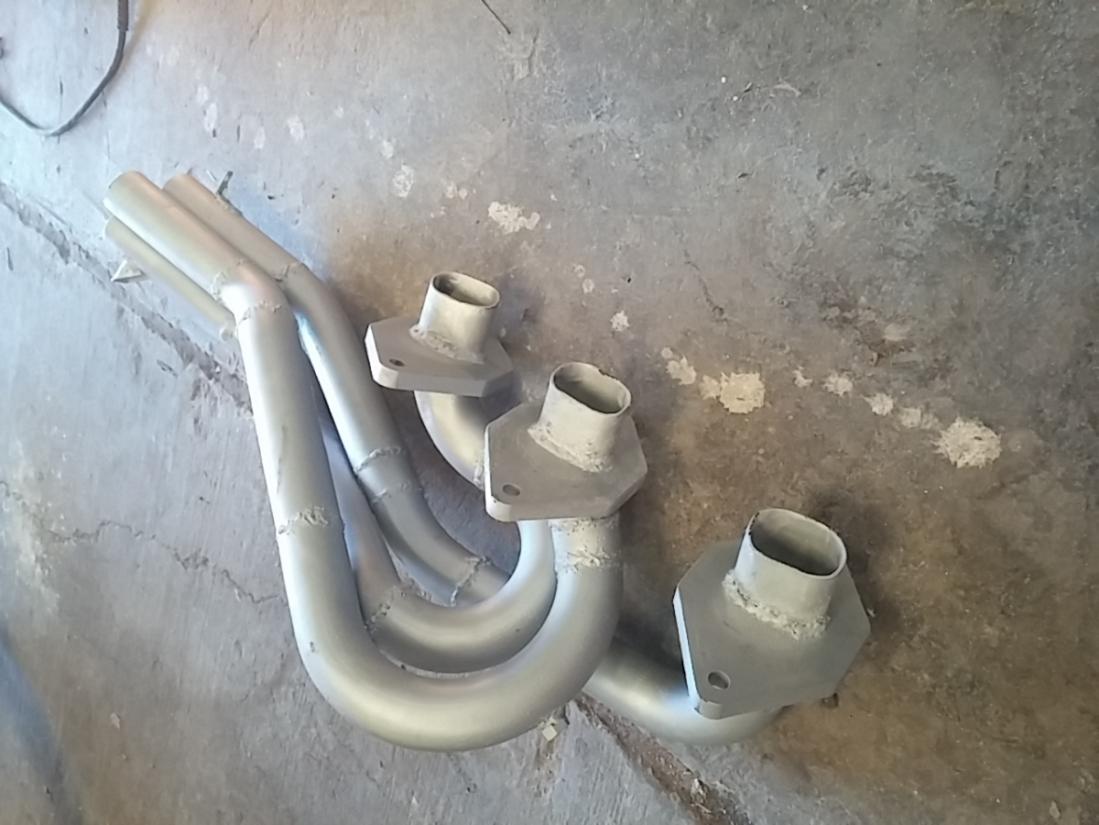
This same header is still on my fd now. I think you would benefit from just running regular NA exhaust gaskets like I am since your exhaust flange faces are now flat.