When you click on links to various merchants on this site and make a purchase, this can result in this site earning a commission. Affiliate programs and affiliations include, but are not limited to, the eBay Partner Network.
Question when creating electric fan wiring - triggered by ECU
Hi guys,
i am needing to create my own wiring harness for running some aftermarket electric fans (custom vmount in my FB so FD fans do not fit and I don't have FD wiring). one fan will be triggered off of 3D from the ECU (Power FC) while the other is triggered by the thermoswitch. can you guys confirm what i have below is correct please (i don't do much wiring so this takes some effort from my little brain)? looks like i will need 3 relays in order to get this accomplished but if you see another way to do this, please let me know.
thanks.
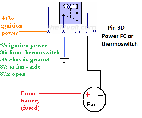
fan 2 relay says power but i changed it to be a ground relay as i think it will be easier to wire.
use this diagram. pick a fan that does the job at one speed. On my FC i had a fan from a Pontiac 6000 to replace the clutch fan. Got the fan off ebay, replaced the motor with replacement one from autozone (because you can fine like any GM part at autozone). Had a custom bracket to mount it on the FC radiator. Or use aftermarket. Whatever works. Don't go overkill on the complexity of the system or the power draw of the fan.
the factory FD system is complicated because #1 they can get away with it because they are OEM and have a gazillion people working on it to make it reliable and #2 they care about being quiet and power consumption at the stock 700rpm idle and accessory loading and all that.
i need to run dual fans cause of size and fitment constraints. BUT i am going to run them like you have shown above with the exception that i am adding a manual toggle switch as well on 86 in conjunction to the thermoswitch, which will ground and allow me to run the fans earlier if needed. my fans are small so may want to manually run them earlier if i know the car will be coming to a stop and not moving for a while.
if the car is coming to a stop, the water temperature will increase. and then the Power FC will turn on. just set the threshold to 86C in the Power FC. It will be fine. Or play around with the setting the FC Edit software and figure out activation temperature works for you. If the fans are sized correctly you're ok. As long as water temps stay under about 220F/105C you're ok, but in general it'd be nice to keep it closer to 180-190F.
if you really want a manual switch, go for it. but it seems like more work and another failure point. Maybe that's just me though, as I like to minimize driver input needed. Like, could I give it to a "normal driver" and have them not need to know any weird/special thing to make it run right?
thanks for the help arghx. i'll wire it up to 3D instead since the threshold can be modified in the PFC (instead of the thermoswitch) and no need for the manual switch.
if you really want a manual switch, go for it. but it seems like more work and another failure point. Maybe that's just me though, as I like to minimize driver input needed. Like, could I give it to a "normal driver" and have them not need to know any weird/special thing to make it run right?
This is a great philosophy to use when doing mods!
wait a second...the 3D wire outputs B+ when the fan should not run. and when it reaches the threshold, it outputs "below 1.0v" for the fans to run. So the top half of my drawing would be the correct way to run it, no?
it's a switched ground for low amperage, which is what you want to trigger the coil on the relay. All you need is like an 18 gauge wire on the coil's +12v and ground side of the relay (pins 86 and 86). You need like a 12 or 10 gauge wire for the actual power and ground to the fan motor.
The wiring diagram I provided is how I ran it on my 2nd gen Rx-7 with Power FC. The Banzai Racing adapter sent the ground signal through the OEM harness into an OEM diagnostic plug, and i just ran a wire from that plug to the terminal on the relay. It's a proven wiring schematic based on post #2 of this thread I made in the second gen section years ago
refer to this Banzai Racing writeup which is for the same kind of thing. It also shows how you can use an OEM 4 pin relay instead of a parts store one.
i've seen that post of yours and it was very helpful. my confusion was due to the B+ in the wiring diagram but if it grounds itself when the fans are supposed to be turned on, great. that makes wiring much easier since it only needs a single relay. glad there are people who understand wiring and are helpful!
could i run 2 relays, both connected to the negative sides of the fans or would it be best to keep one relay per fan? when i ordered my fans, i also bought 2-40amp relays.
How can one run staged fans. I see in the pfc it has an option for fan 1 to come on at one temperature setting and fan 2 to come on at a later temperature. Curious.
 03-06-17, 01:06 PM