LS1/FD Build Thread (the most detailed build thread on Earth)
 05-20-10, 09:01 AM
#1
This is my original build thread of my car. This build thread is ~3 years old and there is a lot that has been changed since then. I'll see if I can find some of those posst to update. Well here goes. This is gonna take a while to post it all up.
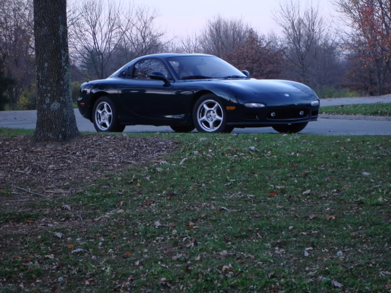
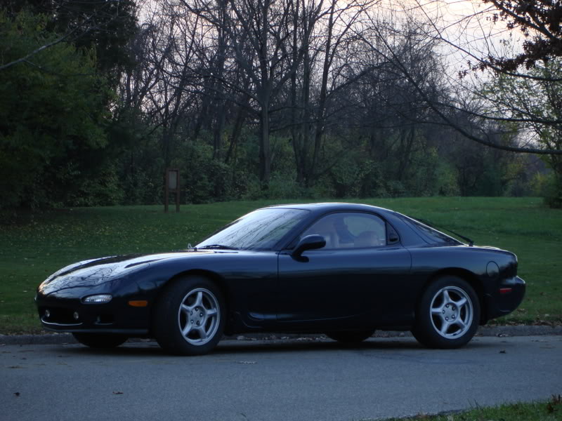
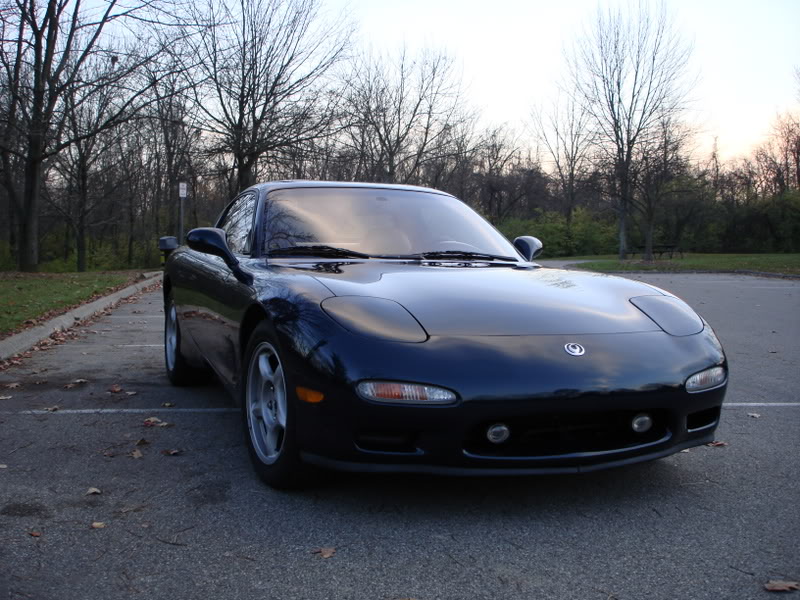
I have a 94 Touring model. I bought it from Maryland. It has 30k original miles on it. It ran perfect when I pulled the rotary and sold it. For anyone curious, I sold the engine/tranny for $3k in perfect running condition. I purchased the car for the sole purpose of swapping it.
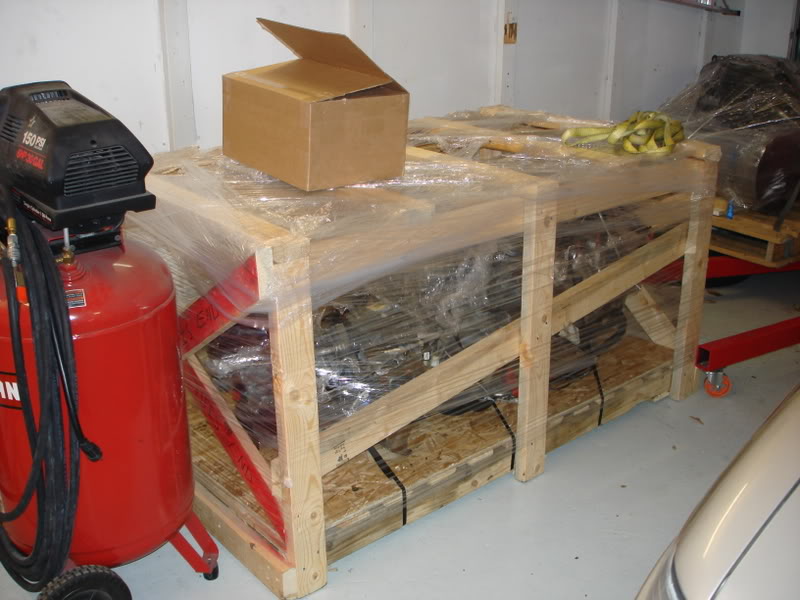
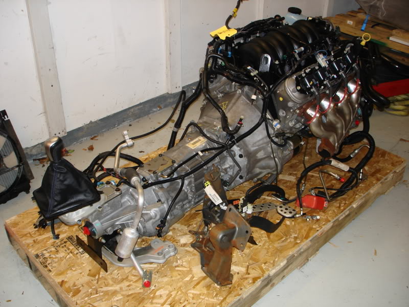
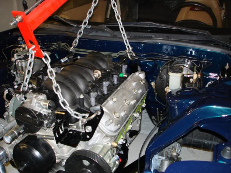
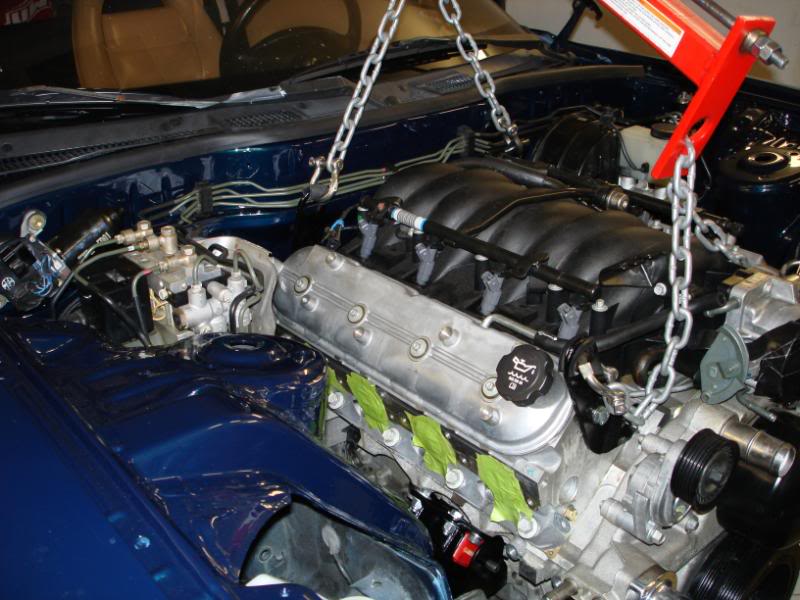
I have an 04 GTO LS1/T56 that I'm putting in.
I'll try to make this a picture documentary.
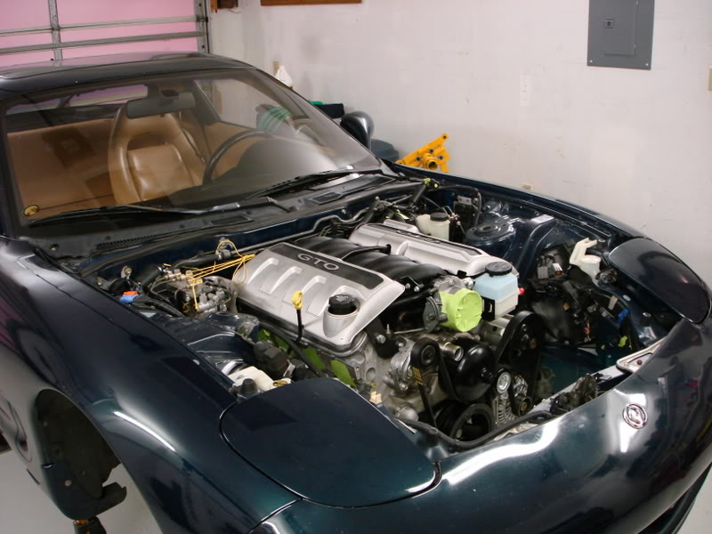
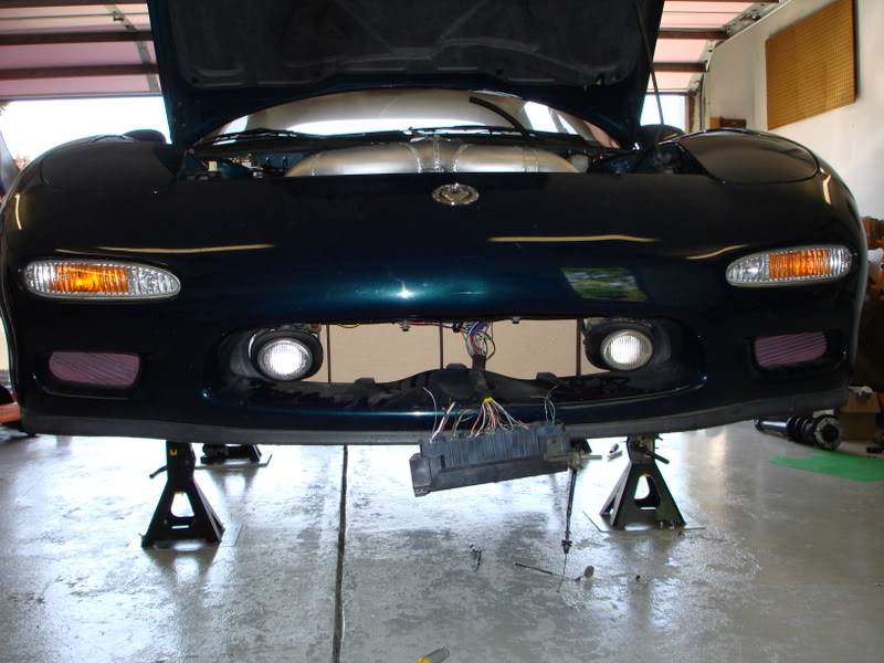
First off, here is the car before I tore out the rotary.
LS1/T56 from Cleveland Pick A Part. Its an 04 GTO engine with 14k miles on it.
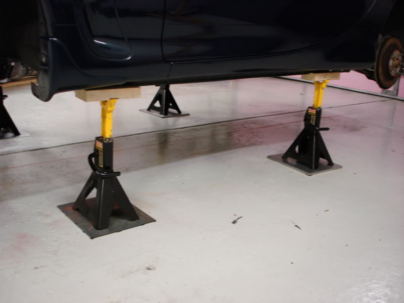
Car up on stands getting ready.
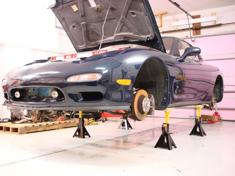
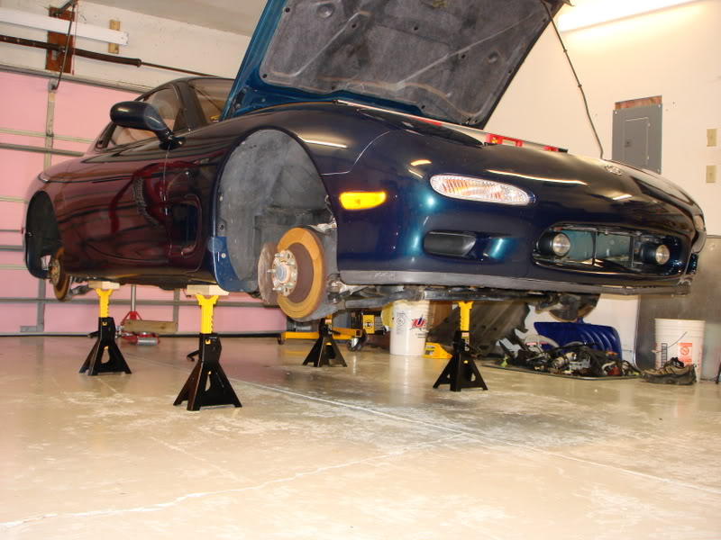
Car shimmed level front to back, and side to side. Gotta have a solid platform to work and measure from.
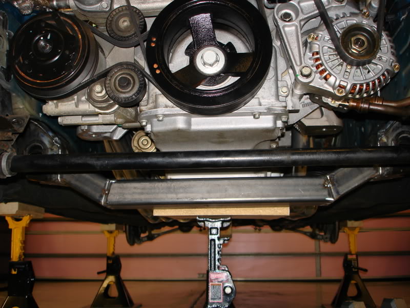
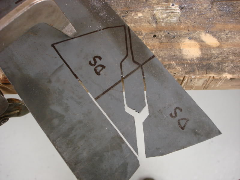
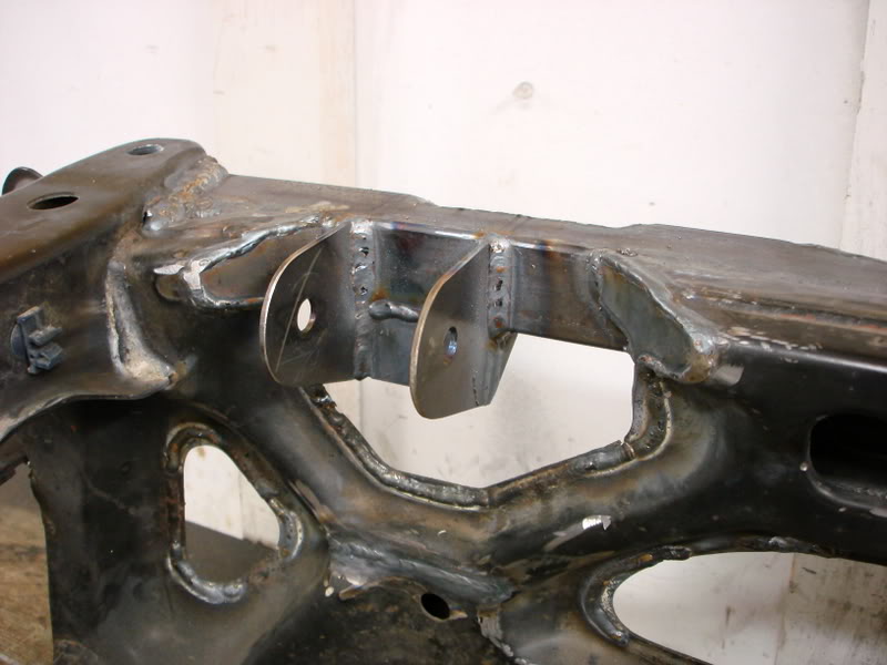
Cutting up stock subrame.
Boxing in control arm ends.
I have a 94 Touring model. I bought it from Maryland. It has 30k original miles on it. It ran perfect when I pulled the rotary and sold it. For anyone curious, I sold the engine/tranny for $3k in perfect running condition. I purchased the car for the sole purpose of swapping it.
I have an 04 GTO LS1/T56 that I'm putting in.
I'll try to make this a picture documentary.
First off, here is the car before I tore out the rotary.
LS1/T56 from Cleveland Pick A Part. Its an 04 GTO engine with 14k miles on it.
Car up on stands getting ready.
Car shimmed level front to back, and side to side. Gotta have a solid platform to work and measure from.
Cutting up stock subrame.
Boxing in control arm ends.
 05-20-10, 09:02 AM
#2
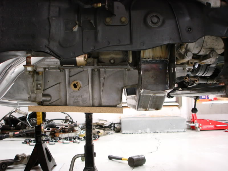
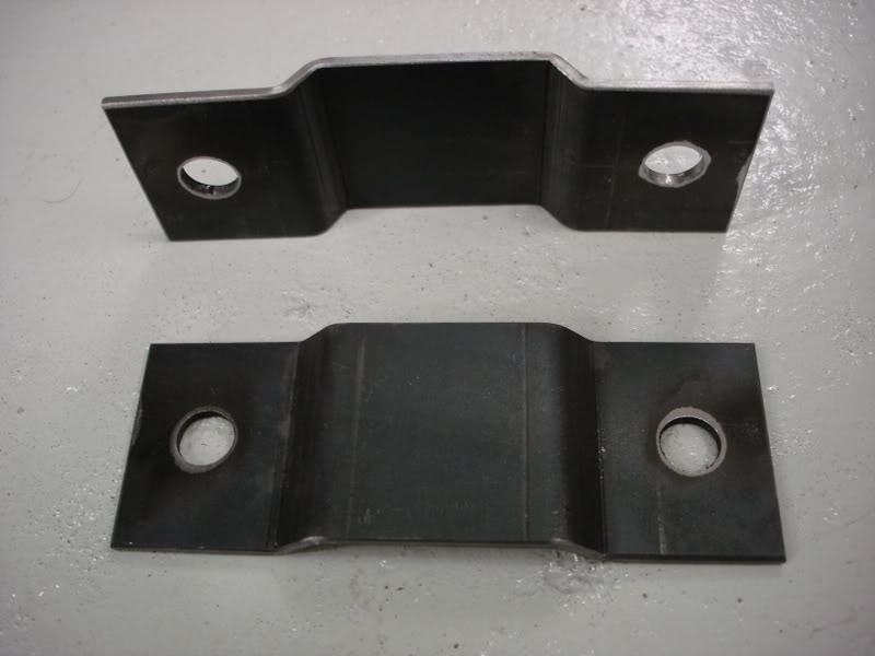
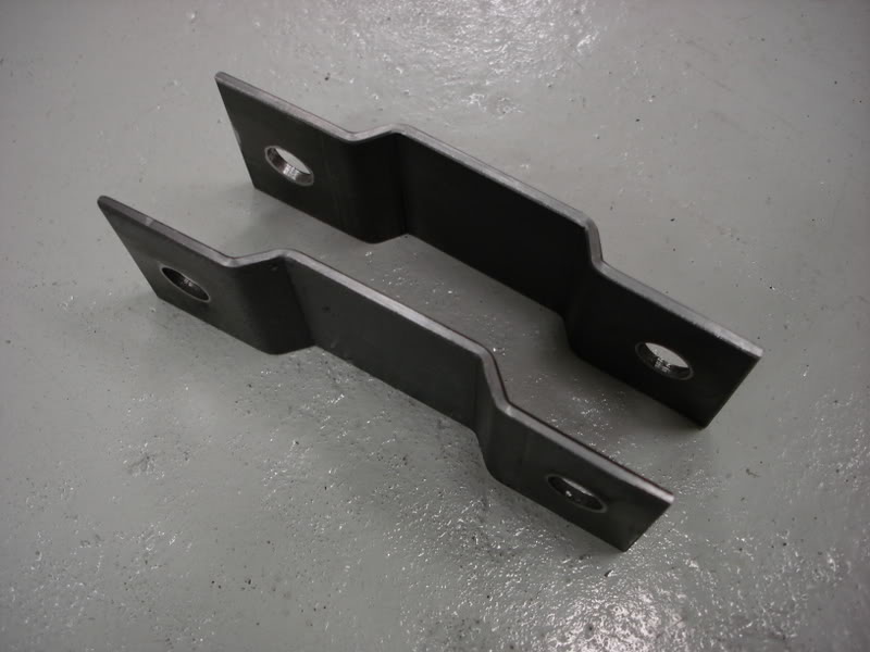
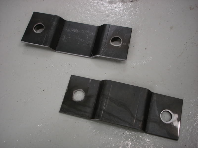
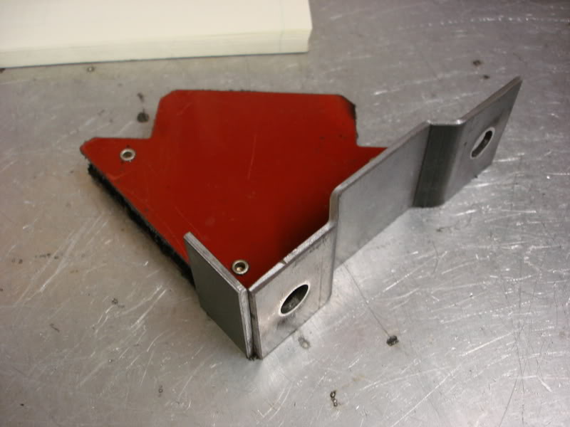
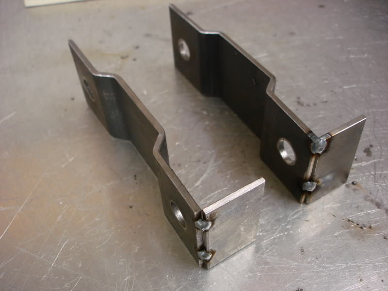
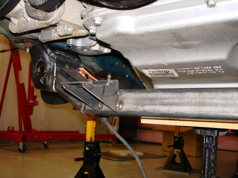
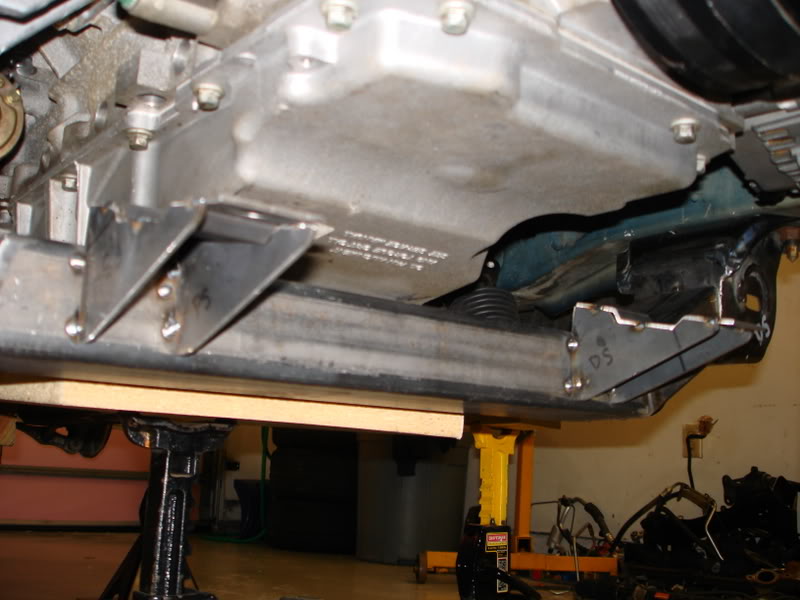
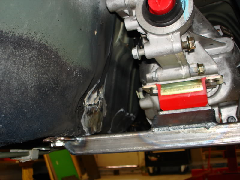
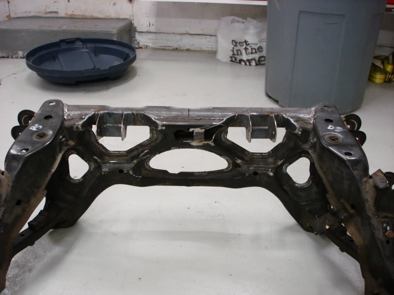
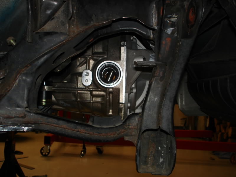
I needed to make custom subframe hoist points because the rear stock one stuck out too far into the firewall. I decided to use a 4 point system for a more level pickup, as opposed to a two point. I used the stock front one, and added another front one on the other head, and made both rears. This now allows me to put the engine as far back it it hits something else. No longer the pinch point.
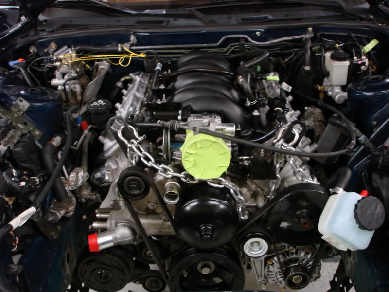
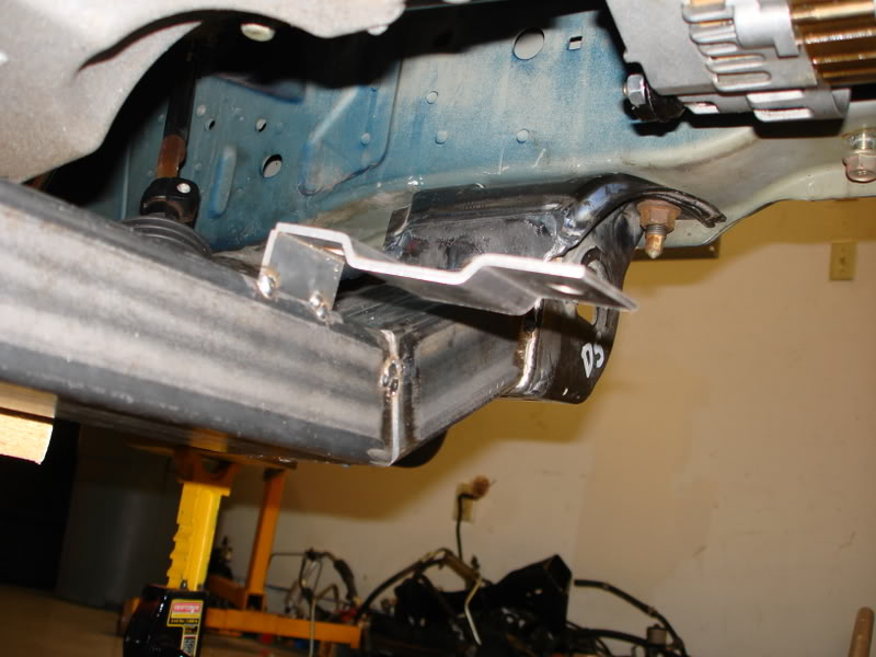
Test fitting. Those covers don't even come close to fitting under the hood.
More test fitting.
Boxed subframe ends in the car.
More trial fitting
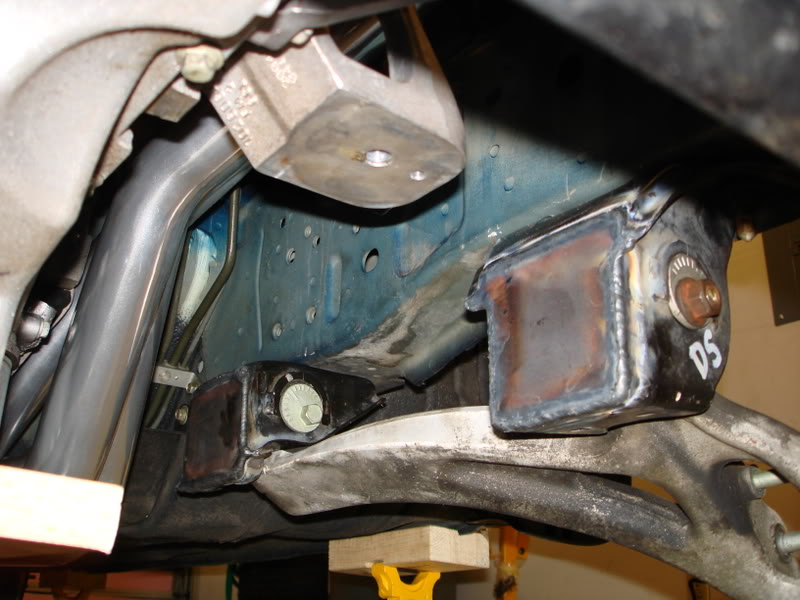
Place where heades hits passenger side firewall/floorboard/tunnel
 05-20-10, 09:03 AM
#3
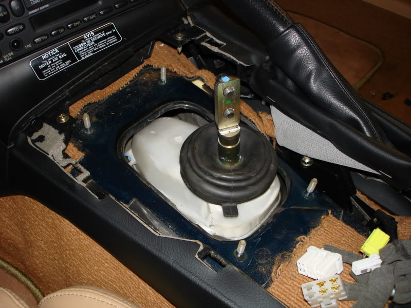
GTO shifter assembly. Looks like this works a bit better than an F-body setup. No cutting necessary, as least most likely not.
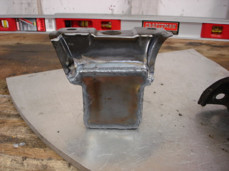
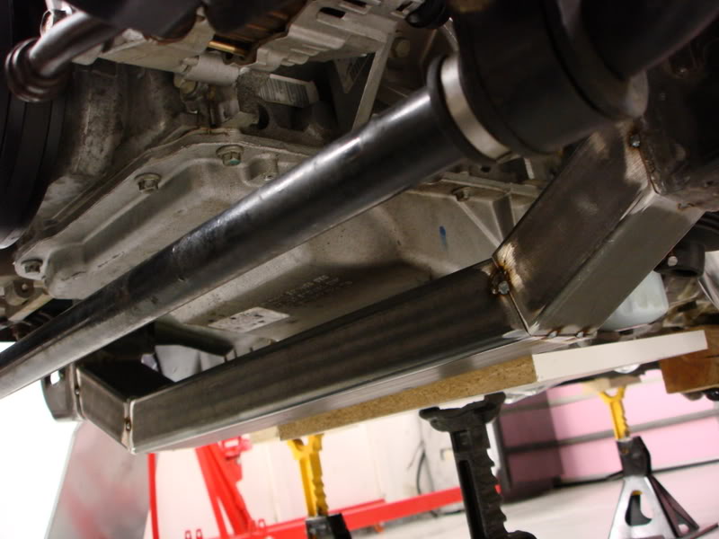
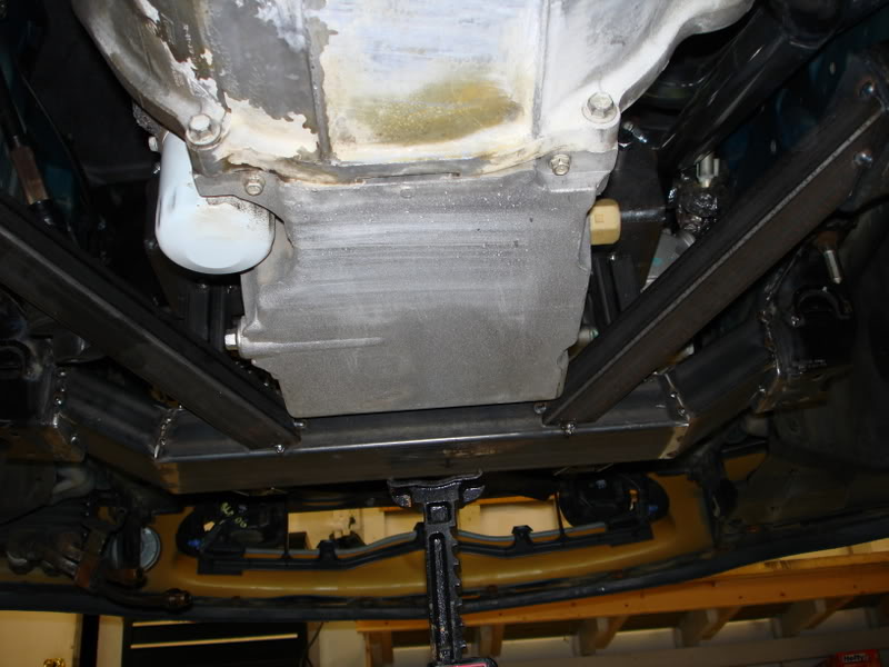
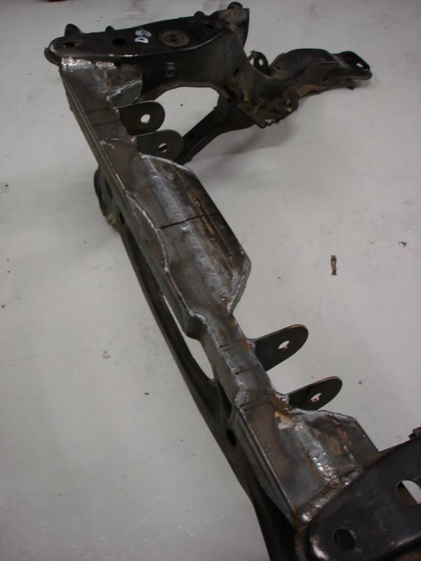
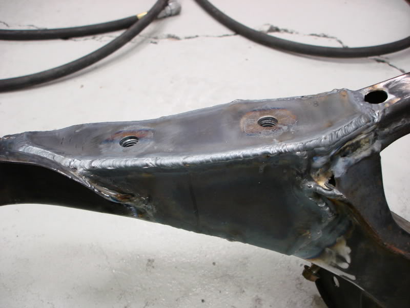
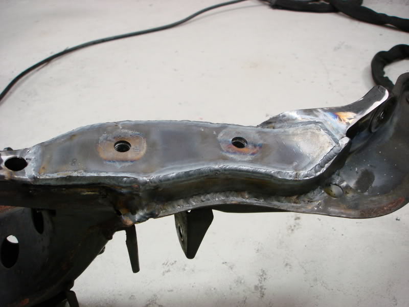
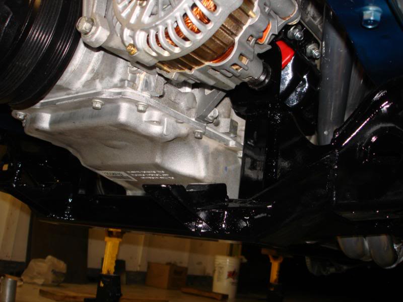
Got a portion of the front subframe tacked in place. There were several things I had to consider when making the subframe. Steering rack input shaft had to be able to clear everything. Steering rack placement. Engine removal, I wanted to be able to remove the engine/trans as a unit, and the subframe has to allow that. The oil pan on the LS1 hangs pretty low, and I wanted the lowest point to be the subframe, not the oil pan. I put the lowest part of the subframe about 1/2 to 3/4" below the lowest portion of the oilpan.
Here are some pics of that.
Nothing exciting today, but I did make some brackets for the steering rack. The simplest things take a good deal of time.
Some progress today. What I just did today was probably the most painstaking part I've done so far. I was extremely precise when placing the steering rack. With the brakets tack welded where they are I have 5/16" clearnace between the rack and oil pan, and 1.75" lower than stock. Chance are I'll move the entire subframe up 3/8" here in the near future, and that will leave me at only 1.375" lower than stock.
I made some small spacer pieces to get the rack to the height I wanted. Here I used a magnetic holder thing. I'm going to be corner welding the bracket. In my previous job, I learned that corner welds are the most desirable type as far as fatigue and strength go.
Tack welded together.
Tack welded to the subframe. This part too forever. I must have measured and adjusted the rack and brackets 2000 times before I put my first tack on there. Some people will question why the brackets are higher than the subframe, and my answer is this. I didn't want the oil pan hanging down below the subframe, and that is the reason the subframe isn't tucking up closer to the oil pan. The subframe is 3/8" lower than the oil pan.
05-20-10, 09:04 AM
#4
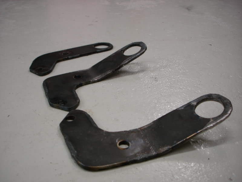
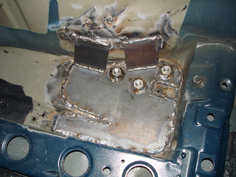
Here is the picture of the support gussets that will be welded in place. I still need to cut them out. If you have a good imagination you'll be able to see how they fit in place. Also, on the drivers side bracket I'm going to put some gussets to the side in addition, because the driver side bracket takes all the side to side load from the rack, and you want that part as sturdy as possible, with little to no flex.
Put on some of the gusseting brackets on the steering rack mounts.
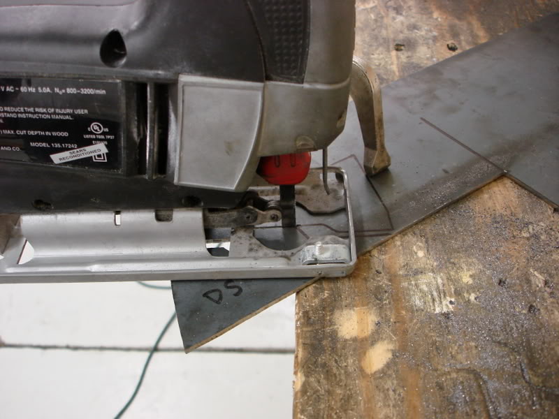
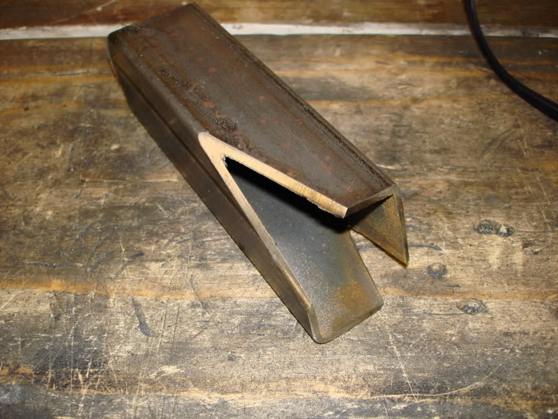
I've got a bunch of PMs about how I cut the metal. This is usually how I cut sheet metal at home. I use a scroll saw then clean up the edges with a combination belt/disc sander, or possibly a bench grinder. Here is the saw I use. Its pretty shitty, but it gets the job done.
Cutting brackets....
Brackets tacked on. I'm leaving it all tacked for now, till I finalize everything, just in case anything needs to change.
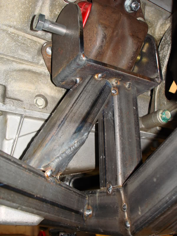
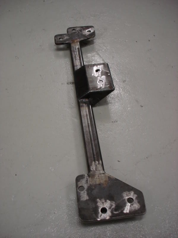
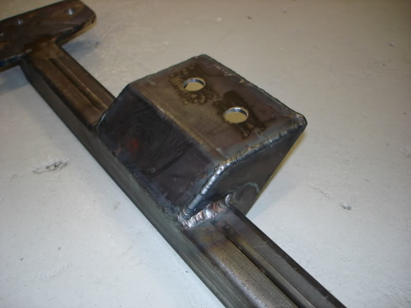
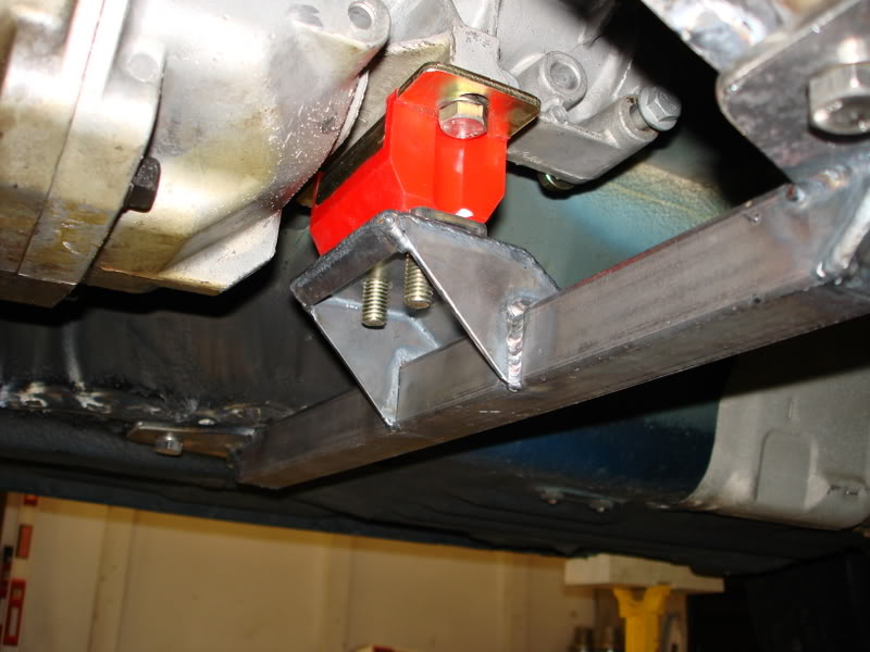
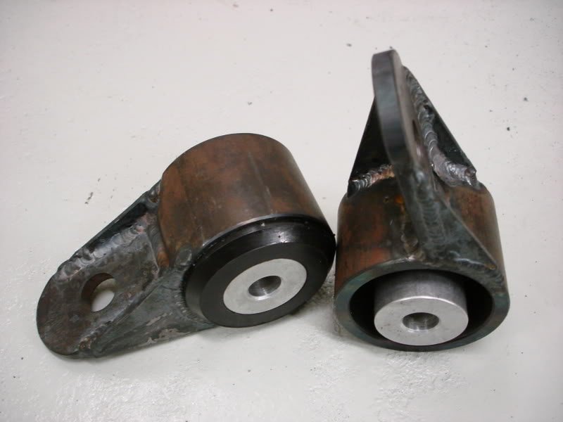
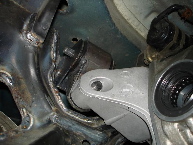
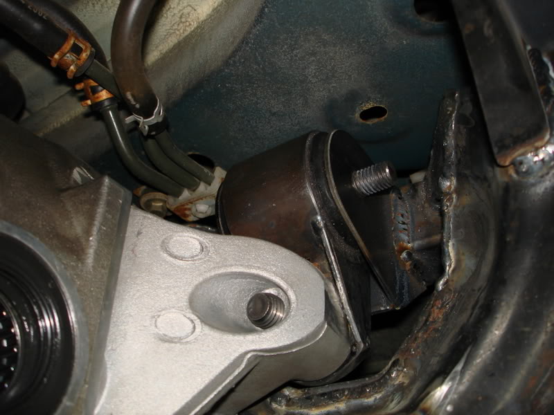
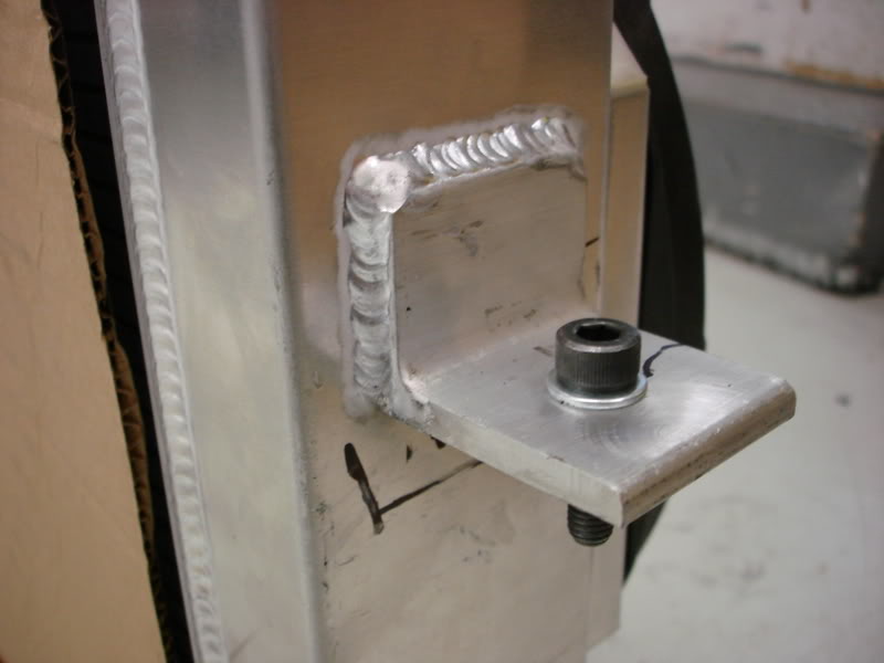
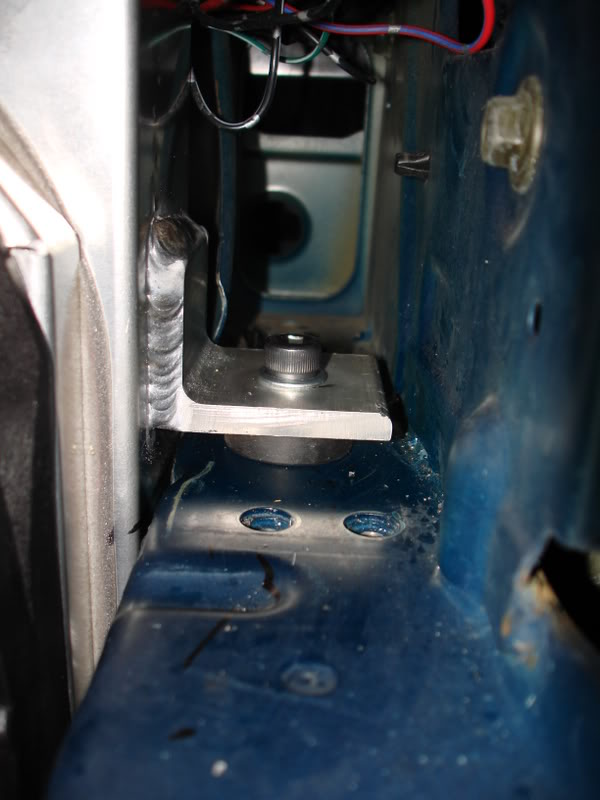
I made some engine mount U-Brackets the other day. The bolt is there to prevent the U-channel didn’t warp inward from the heat of welding. I corner welded, as well as the inside corner for good measure. The bolts used as spacers did the trick.
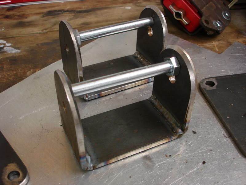
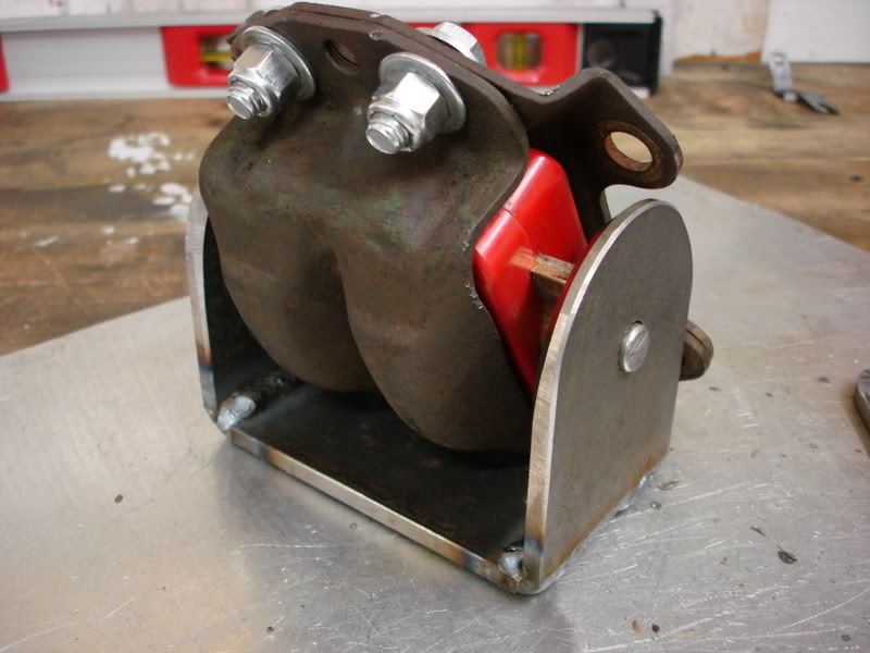
Working on the engine mounts to the subframe. First task: Get the engine supported vertically. Oh yeah, I moved the engine and subframe up �"
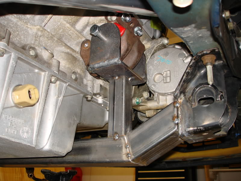
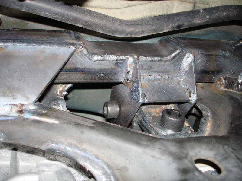
Task two: Put in support tubing to the rear control arm mount. This was required for the next motor mount brace I was planning to add.
Task three: Put in motor mount bracing to make it rigid in the front to back direction. You’ll see why the tube is cut like this in a minute.
Put on some of the gusseting brackets on the steering rack mounts.
I've got a bunch of PMs about how I cut the metal. This is usually how I cut sheet metal at home. I use a scroll saw then clean up the edges with a combination belt/disc sander, or possibly a bench grinder. Here is the saw I use. Its pretty shitty, but it gets the job done.
Cutting brackets....
Brackets tacked on. I'm leaving it all tacked for now, till I finalize everything, just in case anything needs to change.
I made some engine mount U-Brackets the other day. The bolt is there to prevent the U-channel didn’t warp inward from the heat of welding. I corner welded, as well as the inside corner for good measure. The bolts used as spacers did the trick.
Working on the engine mounts to the subframe. First task: Get the engine supported vertically. Oh yeah, I moved the engine and subframe up �"
Task two: Put in support tubing to the rear control arm mount. This was required for the next motor mount brace I was planning to add.
Task three: Put in motor mount bracing to make it rigid in the front to back direction. You’ll see why the tube is cut like this in a minute.
05-20-10, 09:04 AM
#5
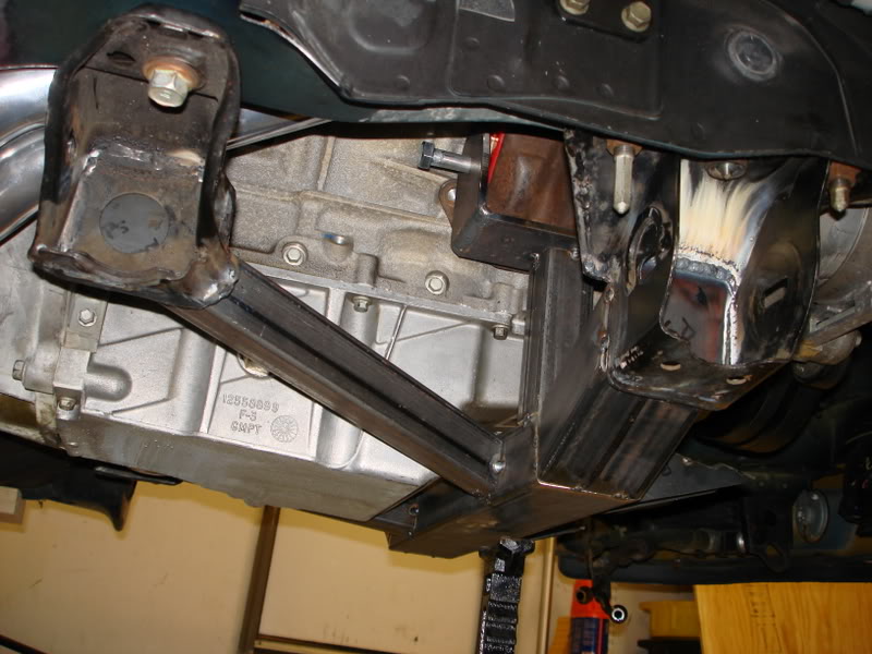
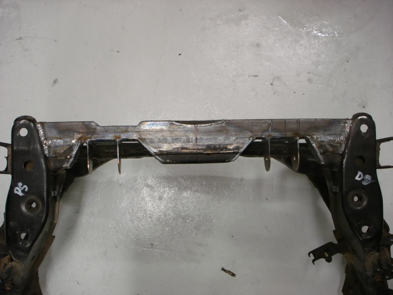
Task four: Add bracing to make the motor mounts rigid in the side to side direction. I used �" sheetmetal for this task. I made them symmetrical, even though the passengers side was able to fit a better brace, but I didn’t think it was necessary.
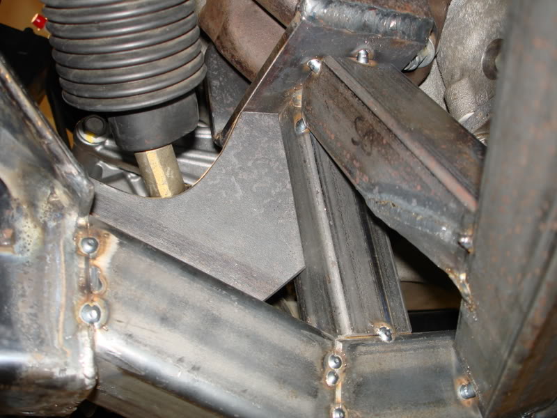
This is as far as I’ve got so far. The front subframe is almost done with mockup, and I’ll be fully welding it soon. Just a few things left, put on some steering rack mount gussets. In light of the Hinson suframe failures I’ll be adding some material near where the main subframe tube meets the control arm mounts.
I caught myself on fire today cutting those plates out with a cutoff wheel. I stopped to see my progress, and what do I see? FLAMES. I was wearing leather gloves so I started to pat it out, but that didn’t seem to work very well. Then the flames started to travel and get bigger, so I made my way to the fire extinguisher. Ended up getting it patted out. Hahahah
Got my Delrin bushings today, thanks TireSmokin7.
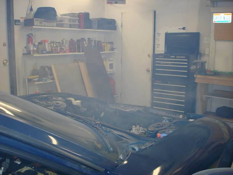
It got a little smoky in the garage with all that burning underbody coating.
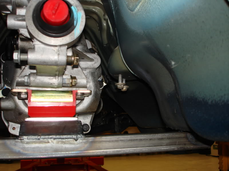
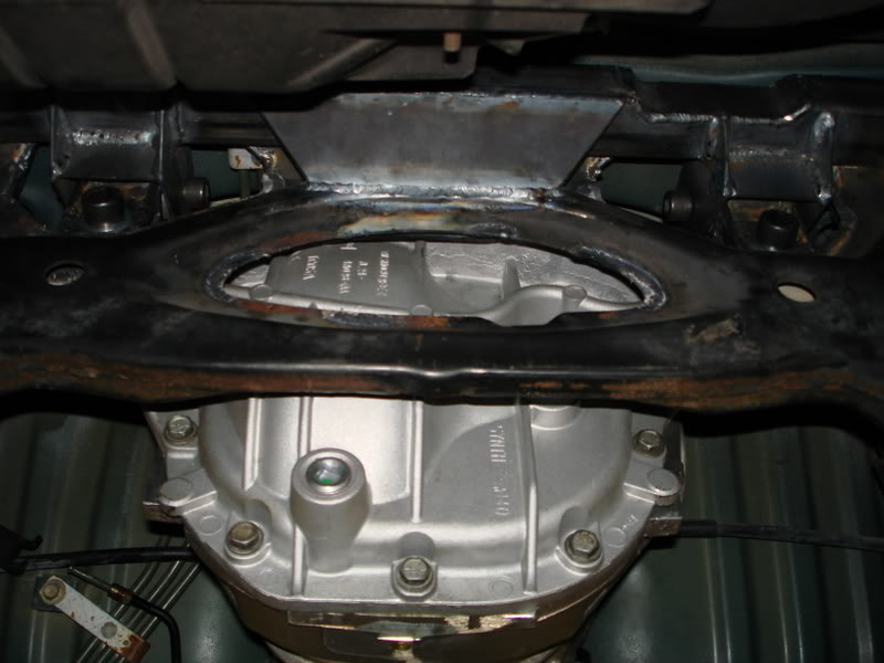
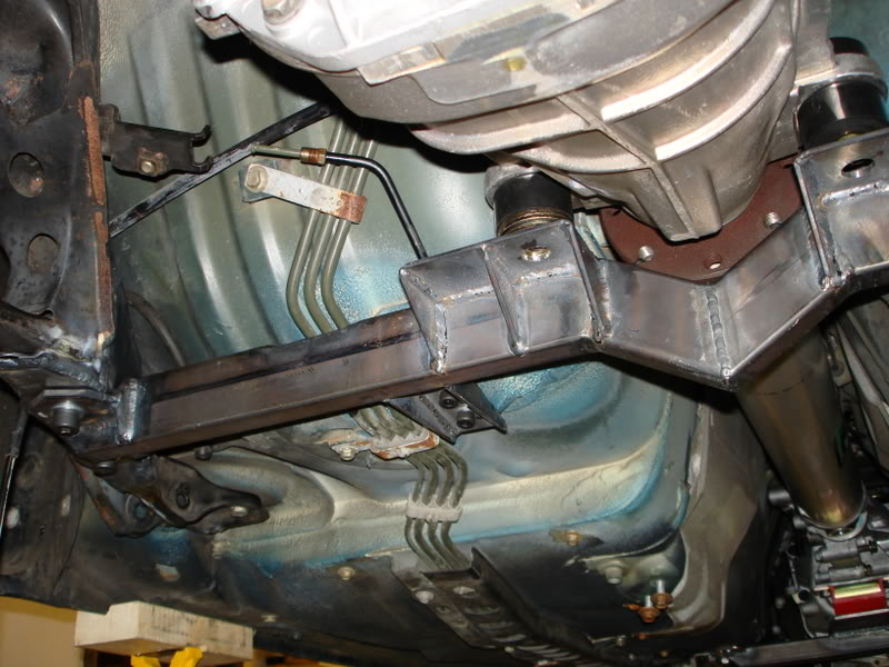
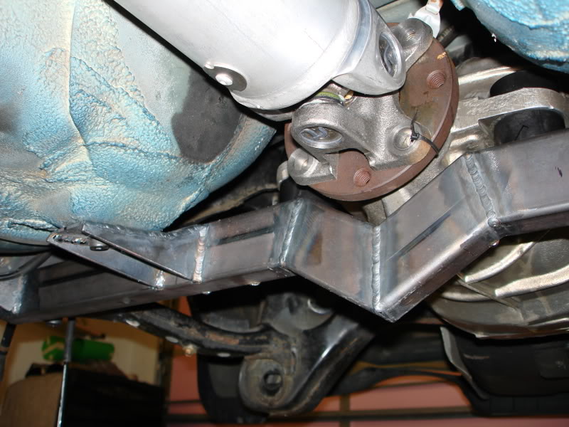
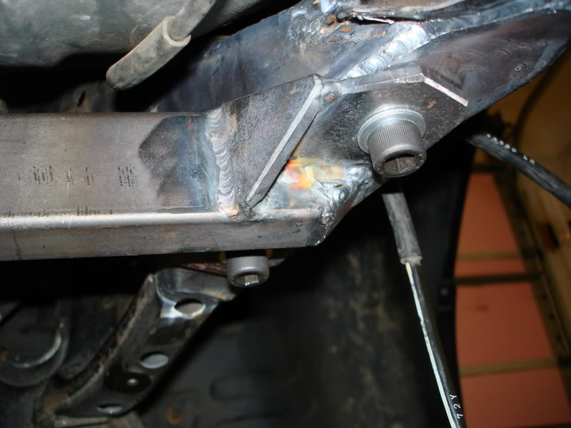
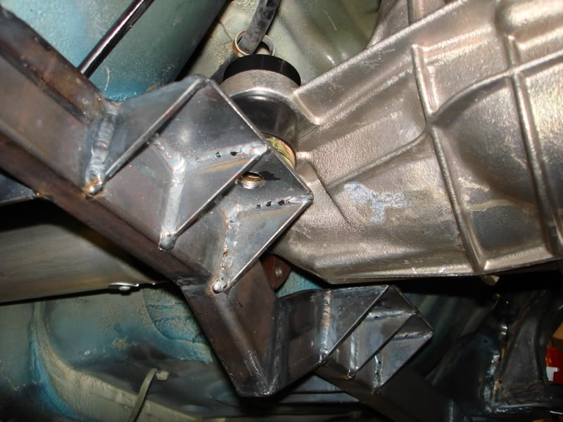
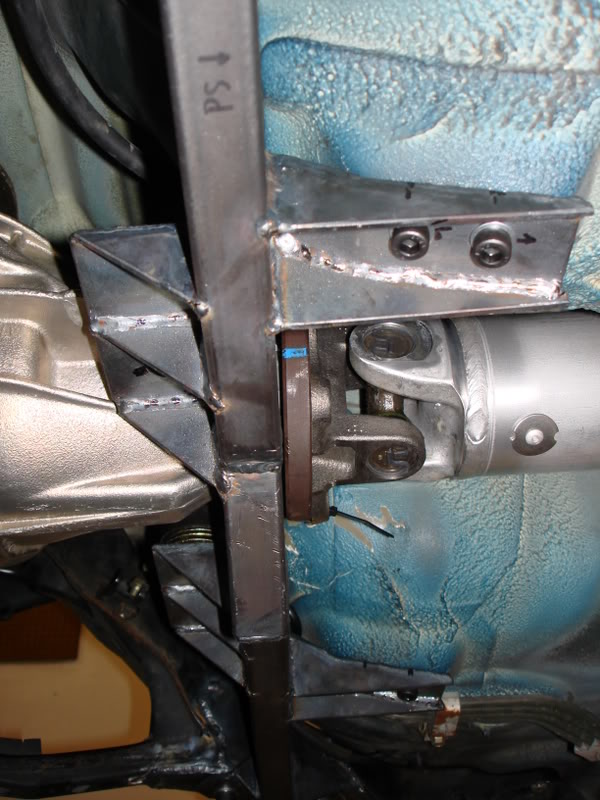
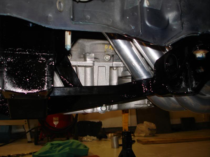
I made the crossmember so I’d be able to change the driveshaft angles by shimming the transmission up or down. It can currently go down �" or up �". As it currently sits, it should be prefect 1.5 degrees at each joint. Here is how the crossmember turned out.
This is as far as I’ve got so far. The front subframe is almost done with mockup, and I’ll be fully welding it soon. Just a few things left, put on some steering rack mount gussets. In light of the Hinson suframe failures I’ll be adding some material near where the main subframe tube meets the control arm mounts.
I caught myself on fire today cutting those plates out with a cutoff wheel. I stopped to see my progress, and what do I see? FLAMES. I was wearing leather gloves so I started to pat it out, but that didn’t seem to work very well. Then the flames started to travel and get bigger, so I made my way to the fire extinguisher. Ended up getting it patted out. Hahahah
Got my Delrin bushings today, thanks TireSmokin7.
It got a little smoky in the garage with all that burning underbody coating.
I made the crossmember so I’d be able to change the driveshaft angles by shimming the transmission up or down. It can currently go down �" or up �". As it currently sits, it should be prefect 1.5 degrees at each joint. Here is how the crossmember turned out.
05-20-10, 09:05 AM
#6
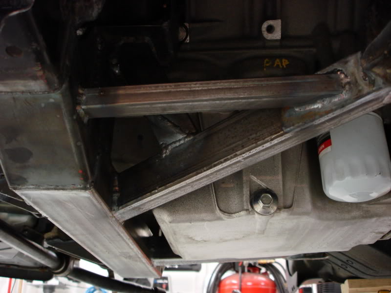
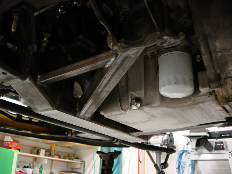
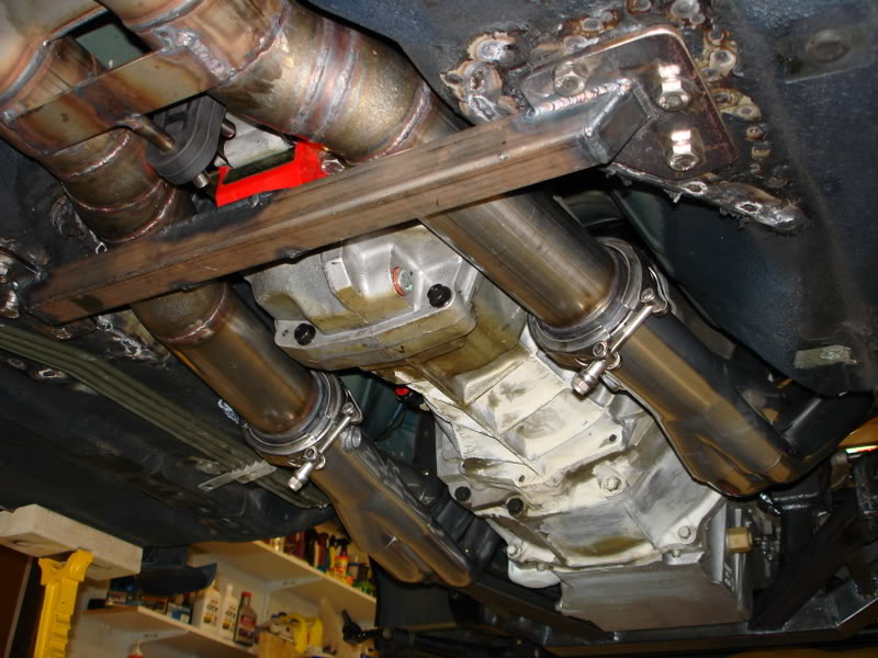
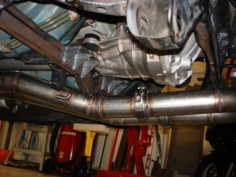
Plenty of room for my 3" dual exhaust to run over the crossmember. It hangs down only 3/8" lower than the stock floorboards.
I got all my exhaust components.
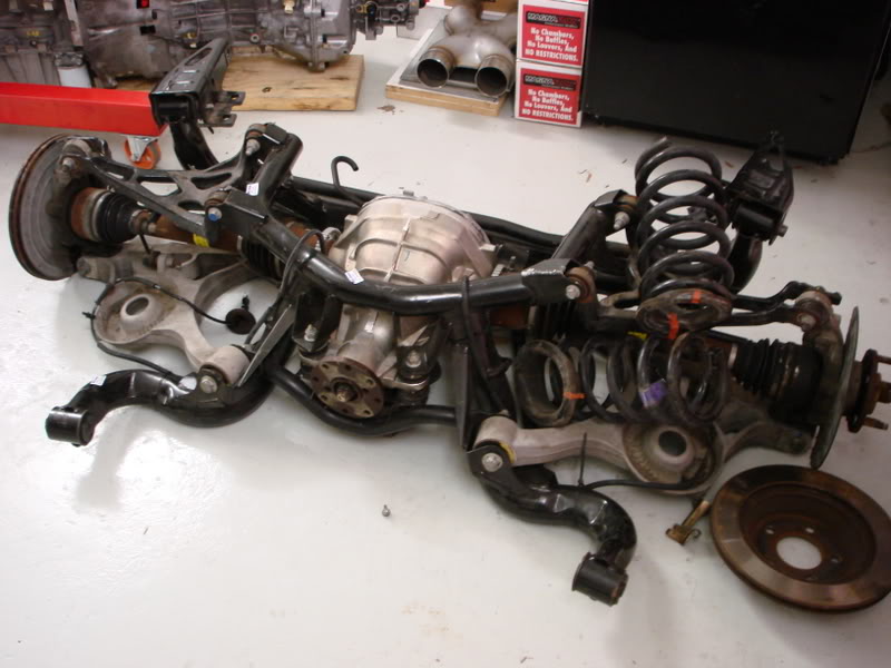
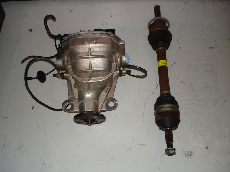
After much deliberation I also decided to go with a cobra rear diff. I decided this for a few reasons. Gear ratio selection, LSD/Spool options, easier mounting with the tabs on the front, etc.
I also started the wiring with help of Dan.
Little update, no pics this time though.
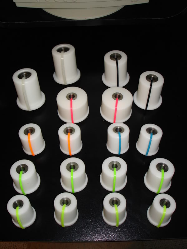
I'm working on getting the cobra diff mounted. I'm using an explorer rear diff cover. I'm going to mount it with poly bushings on all 4 corners. For the poly bushings I need to have shells made to press the bushings into. I bought a piece of 2.375" OD, 1/4" wall DOM. I'm having the ID bored out to 1.935". The bushing that I'm using has an OD of 1.950". This should give me a sufficient press fit. My good friends at Kordenbrock Motorsports (www.kms-fab.com) are doing the machine work to bore out the tubing at their family owned machine shop, Kordenbrock Tool and Die.
I made some exciting purchases as well. I bougth this stuff:
Magic Stick 4 camshaft (Texas Speed and Performance) .649/.609 lift with 111 LSA
PRC dual springs
Ti retainers
Spring seats
Seals
Hardened Chromoly pushrods
LS2 Timing chain
GM cam gasket kit
Ported LS6 oil pump shimmed a touch
ARP rod bolts
Porterfield R4-S front and rear brake pads
Brembo slotted and zinc plated rotors
SS lines
Motul fluid
I just got done spending a lot of time on the cobra rear setup. I’m very happy with how it turned out.
First, I decided to use the Ford Explorer rear differential cover instead of the cobra cover for two reasons. One, they have a tendency to break. Two, mounting would be easier, and have a better hold on the rear end, and I think will lead to less/no wheel hop.
I made some brackets and for the bushings to press in, and to mount to the subframe.
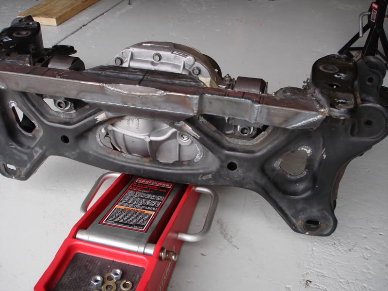
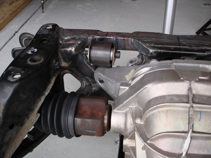
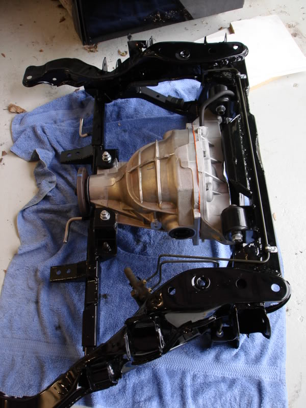
Then I needed to do some modifications to the rear subframe to allow for the cobra diff to be mounted. To determine the location of the diff I kept a few things in mind. The axles need to be equal length, so the output shaft machined “flanges" must be equidistant from the centerline of the car. The diff must also be parallel with the centerline of the car. The axles must also be on the same plane along the distance of the car. This will keep the correct axle joint angles. One thing I did think about was the height of the axle outputs. I was attempting to keep them at stock location or up to 1 inch above. Moving the diff upward would help get the axle joint angles back to stock when the car is lowered. I ended up settling for 0.75" higher than stock, which seemed to work out well. The last important think to consider is driveshaft angles. Both angles must be within 0.5 degrees from of each other, and both must be between 1.5 degrees and 3 degrees. The minimum of 1.5 degrees is for bearing lubrication. 1.5 is the recommended min angle for IRS cars. I shot for 2.0 degrees and hit it within 0.1. Both angles are identically 2.1 degrees. Perfect!
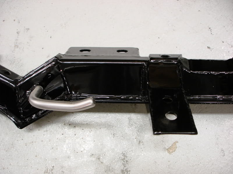
Here are a few pics of the rear subframe modifications for mounting the cobra diff. I basically welded in a piece of square tubing to the rear of the subframe. Then I welded mounting tabs off that. I had to notch the square tubing in two locations, one for the rear sway bar, the second for the fuel tank hangers. I also welded the remaining parts of the subframe that were only stitch welded from the factory.
I got all my exhaust components.
After much deliberation I also decided to go with a cobra rear diff. I decided this for a few reasons. Gear ratio selection, LSD/Spool options, easier mounting with the tabs on the front, etc.
I also started the wiring with help of Dan.
Little update, no pics this time though.
I'm working on getting the cobra diff mounted. I'm using an explorer rear diff cover. I'm going to mount it with poly bushings on all 4 corners. For the poly bushings I need to have shells made to press the bushings into. I bought a piece of 2.375" OD, 1/4" wall DOM. I'm having the ID bored out to 1.935". The bushing that I'm using has an OD of 1.950". This should give me a sufficient press fit. My good friends at Kordenbrock Motorsports (www.kms-fab.com) are doing the machine work to bore out the tubing at their family owned machine shop, Kordenbrock Tool and Die.
I made some exciting purchases as well. I bougth this stuff:
Magic Stick 4 camshaft (Texas Speed and Performance) .649/.609 lift with 111 LSA
PRC dual springs
Ti retainers
Spring seats
Seals
Hardened Chromoly pushrods
LS2 Timing chain
GM cam gasket kit
Ported LS6 oil pump shimmed a touch
ARP rod bolts
Porterfield R4-S front and rear brake pads
Brembo slotted and zinc plated rotors
SS lines
Motul fluid
I just got done spending a lot of time on the cobra rear setup. I’m very happy with how it turned out.
First, I decided to use the Ford Explorer rear differential cover instead of the cobra cover for two reasons. One, they have a tendency to break. Two, mounting would be easier, and have a better hold on the rear end, and I think will lead to less/no wheel hop.
I made some brackets and for the bushings to press in, and to mount to the subframe.
Then I needed to do some modifications to the rear subframe to allow for the cobra diff to be mounted. To determine the location of the diff I kept a few things in mind. The axles need to be equal length, so the output shaft machined “flanges" must be equidistant from the centerline of the car. The diff must also be parallel with the centerline of the car. The axles must also be on the same plane along the distance of the car. This will keep the correct axle joint angles. One thing I did think about was the height of the axle outputs. I was attempting to keep them at stock location or up to 1 inch above. Moving the diff upward would help get the axle joint angles back to stock when the car is lowered. I ended up settling for 0.75" higher than stock, which seemed to work out well. The last important think to consider is driveshaft angles. Both angles must be within 0.5 degrees from of each other, and both must be between 1.5 degrees and 3 degrees. The minimum of 1.5 degrees is for bearing lubrication. 1.5 is the recommended min angle for IRS cars. I shot for 2.0 degrees and hit it within 0.1. Both angles are identically 2.1 degrees. Perfect!
Here are a few pics of the rear subframe modifications for mounting the cobra diff. I basically welded in a piece of square tubing to the rear of the subframe. Then I welded mounting tabs off that. I had to notch the square tubing in two locations, one for the rear sway bar, the second for the fuel tank hangers. I also welded the remaining parts of the subframe that were only stitch welded from the factory.
05-20-10, 09:06 AM
#7
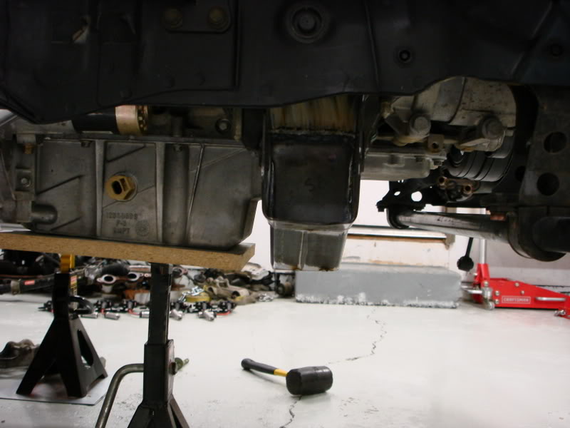
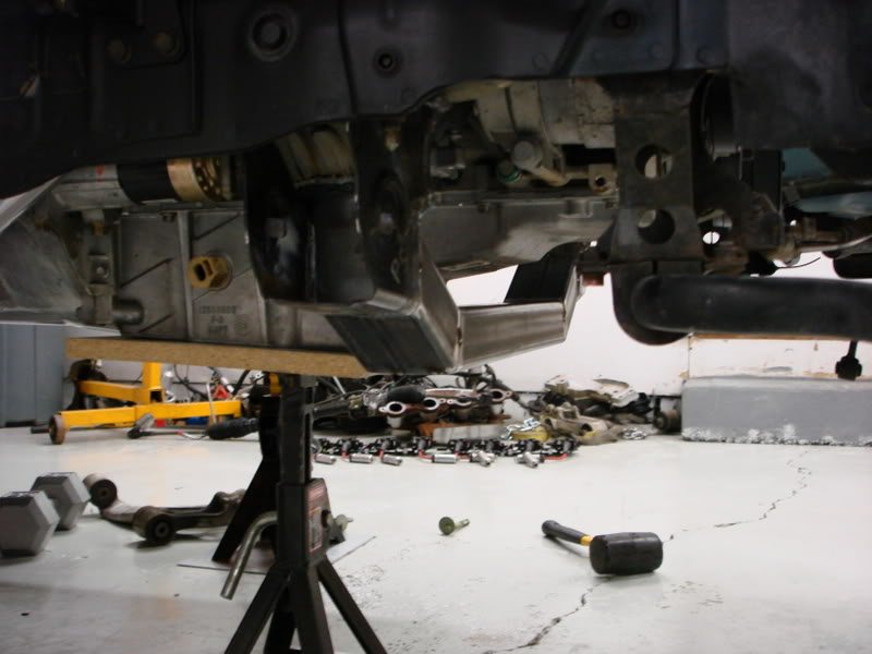
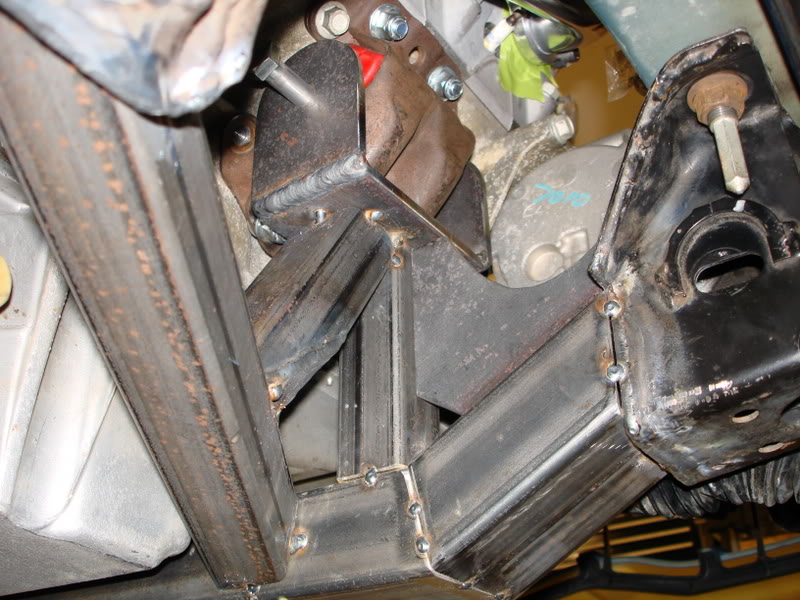
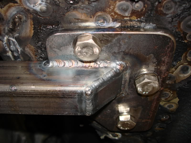
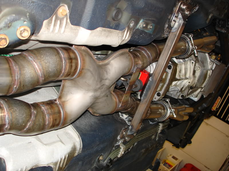
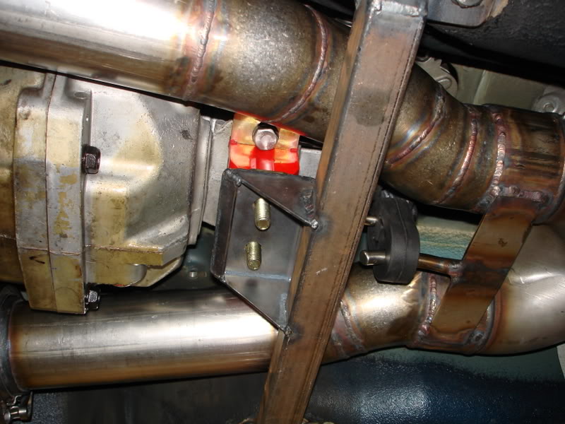
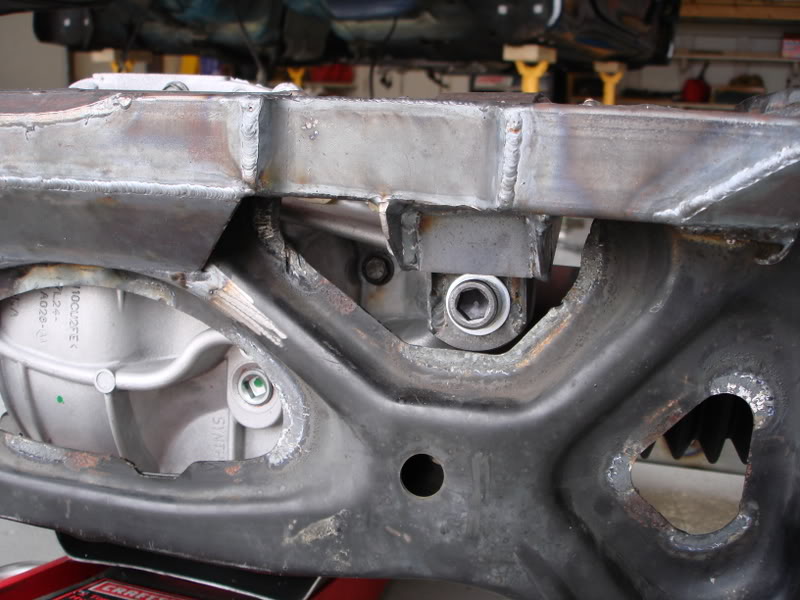
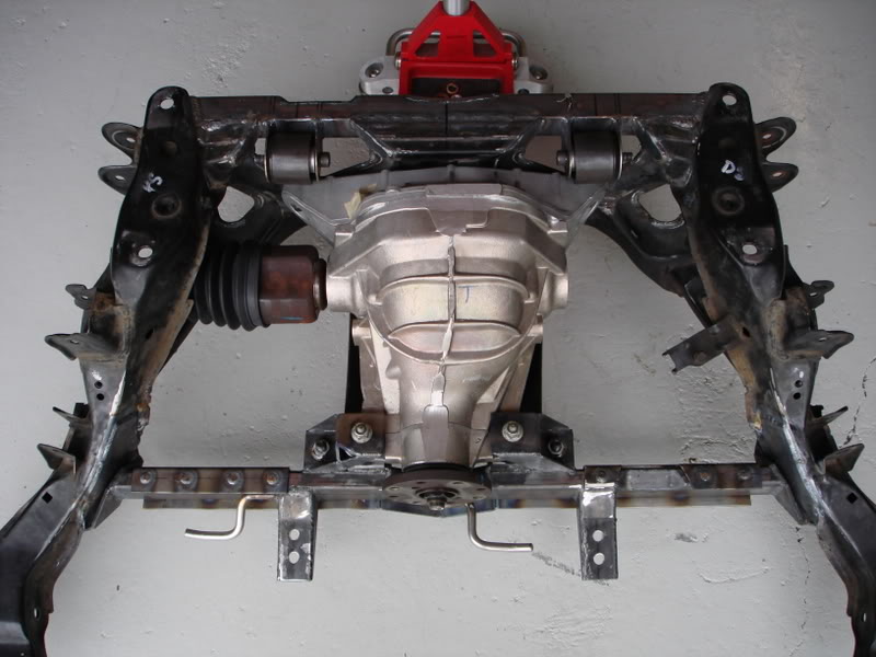
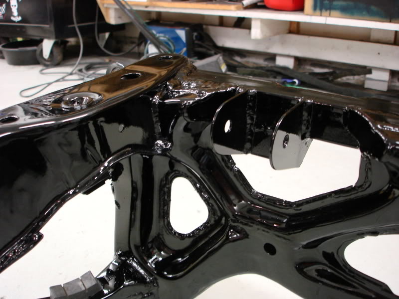
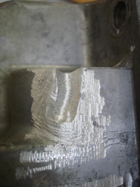
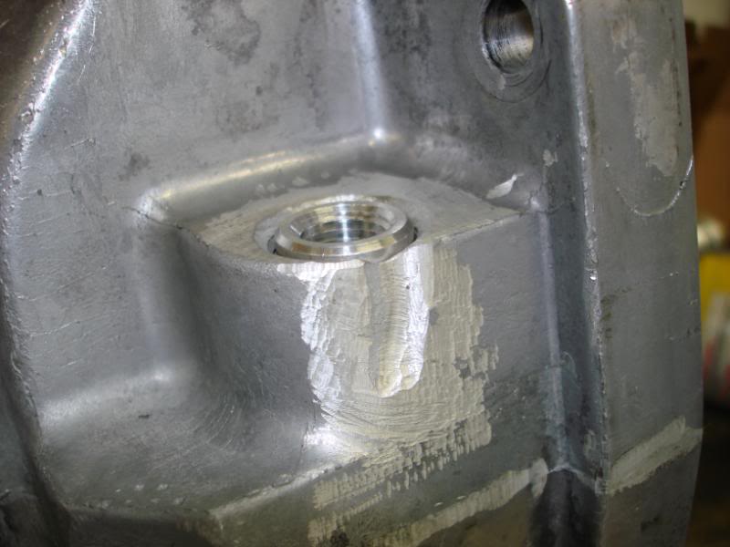
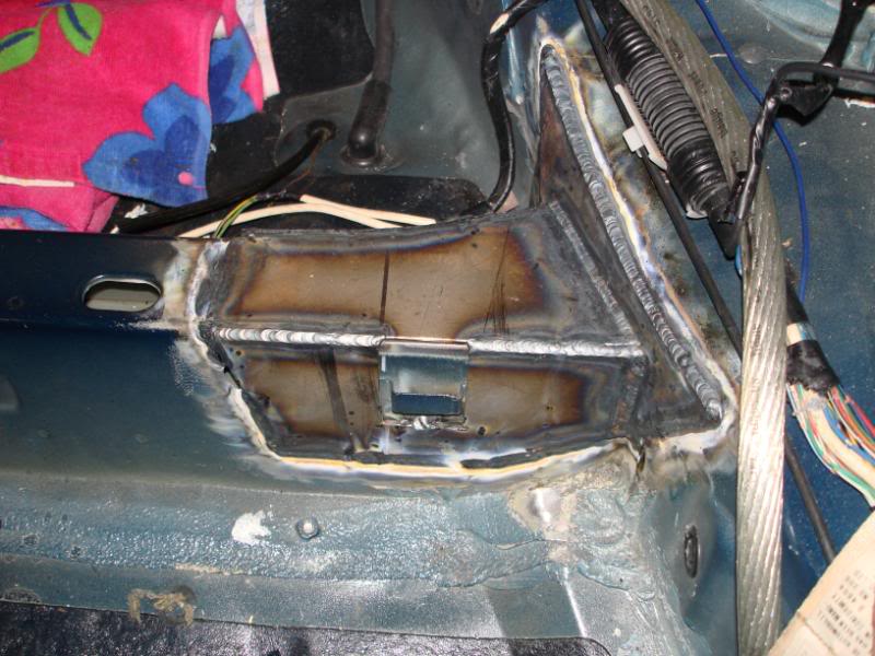
For mounting the front of the diff I thought about many different ideas, over a period of probably a week and had one of my engineering friends come over and help with brainstorming. He ended up coming up with the winning idea. It is simple, easy to remove (for diff removal in the car), easy to fabricate, and should prove to be very strong. Basically its just a cross member that attaches to the subframe. On the subframe I needed some strong attachment points since it will be a highly loaded member. I boxed in an area of the subframe. It consists of three plates welded to the subframe, giving three planes for load distribution. The bottom plate I welded nuts to the backside. Here are some pictures of the boxed area of the subframe.
I tried to keep the subframe as high off the ground as possible, which lead to the current design. The V part looks low, but it is in fact higher than many stock parts of the car. The subframe is 2" x 1" tubing. It attaches to the subframe on the ends, and near the middle, it attaches to the floorboard of the car. The part where it attaches to the floor is a strong area. The Japanese FDs come with rear seats, and right in that area is where the stock rear seatbelts attached, so that area is reinforced with thick sheet metal. It is also on a corner, which increases strength. One thing I still need to do is seam weld the sheet metal in that area because its only spot welded from the factory. The attachment to the body in those spots is what I think really makes the cross member strong. Here are some pics of the cross member.
In the middle of the cross member there are pads for mounting the front of the diff. You can see that they are extra wide. Half of the pad is for the bolt, and main bushing to go through. The second outer half of the pad is for an upper pinion brace that is not made yet, but it will bolt to that portion of the pad.
The cobra diff mounting is done, and only minor modifications still remain. For exhaust routing I intend to go under the cross member, and made some round-oval-round conversions so that I don�t go any lower than the stock floorboards.
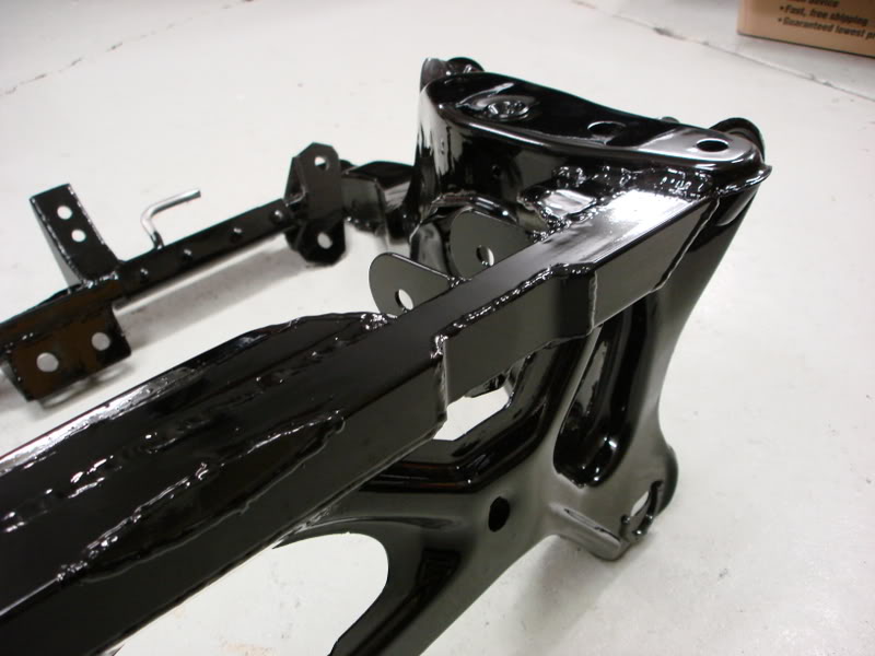
Finally, I put the final touches on the front subframe. When I originally did the finish welding on the front subframe I had a lot of warping, and the lower rear control arm mount point no longer lined up with the bolt hole. I cut the mounting ears off, and re-welded them back on. I also added a small piece of square tubing to help stiffen that leg up, which I think will help considerably. Now it bolts up nicely, and the control arm fits great as well.
Trending Topics
05-20-10, 09:06 AM
#8
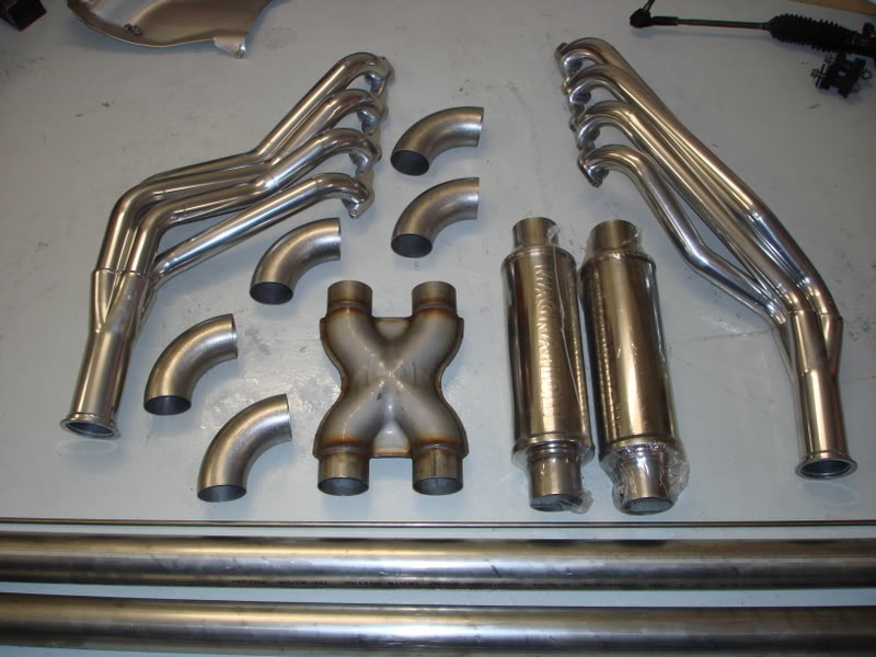
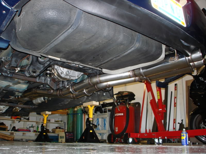
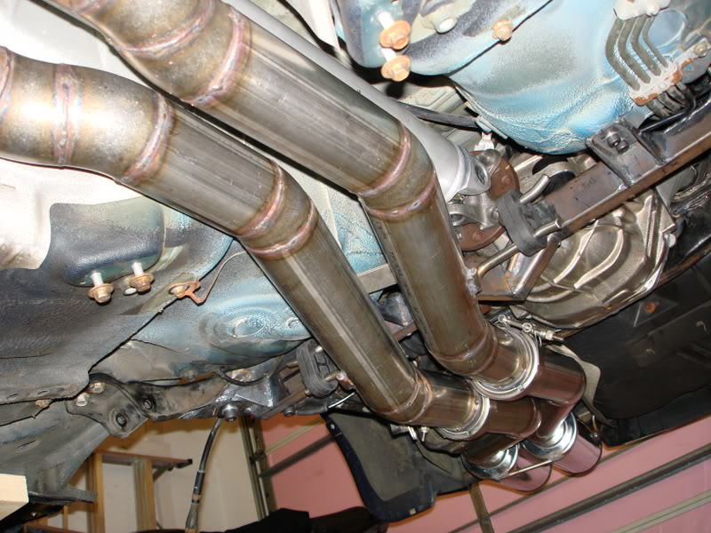
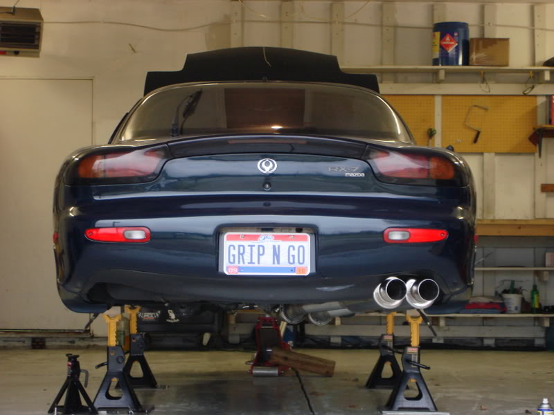
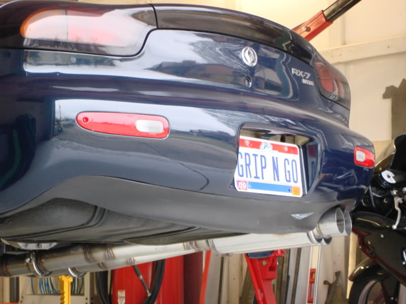
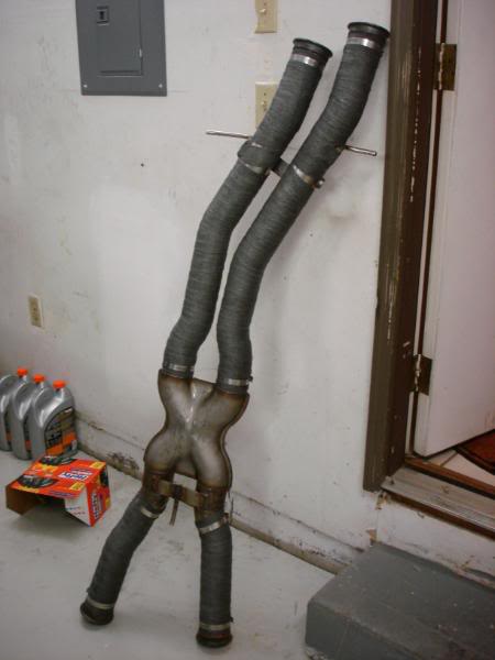
I just finished up my exhaust. It consists of 1.875" long tube headers. 3" collectors, to V-Band flanges. Ceramic coated. 3" stainless to a stainless 3" x-pipe. Then 3" dual all the way back to two stainless Magnaflow mufflers.
Its just straights and mandrel pieces cut and welded to fit. I used approximately 8� of straight, and 6 90s for the entire thing. I used 7/16" 304SS hanger material. The rubber isolators are from AutoZone.
Its fully TIG welded. I backpurged the entire thing when welding, so the interior of the pipe is perfectly smooth. This was a major pain in the ***, but I think it was worth the extra pain, and cost of argon.
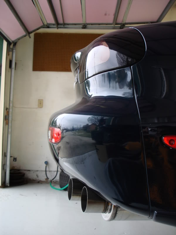
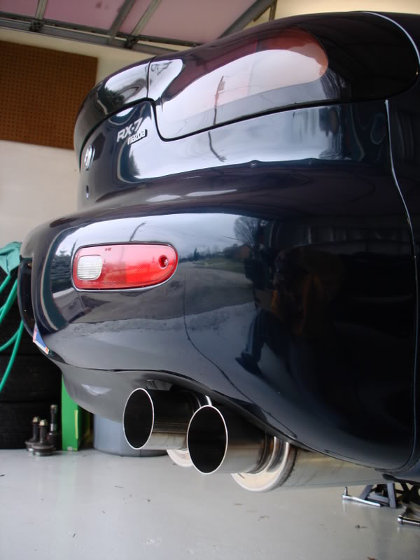
Enjoy!
I want to make sure you get real familiar with this view. LOL.
Its just straights and mandrel pieces cut and welded to fit. I used approximately 8� of straight, and 6 90s for the entire thing. I used 7/16" 304SS hanger material. The rubber isolators are from AutoZone.
Its fully TIG welded. I backpurged the entire thing when welding, so the interior of the pipe is perfectly smooth. This was a major pain in the ***, but I think it was worth the extra pain, and cost of argon.
Enjoy!
I want to make sure you get real familiar with this view. LOL.
05-20-10, 09:07 AM
#9
Thanks. It wasnt' too bad once I figured how how much to flow in the backpurge. It took some experimenting, but the results are amazing!
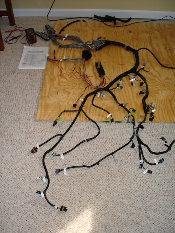
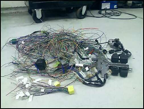
Over the past few days I've been working on chassis wiring.
So far I've just been stripping wires out that I won't need from the engine bay body harness.
I've removed:
Both fuel pump relays and associated wiring
Fuel pump resistor and associated wiring
EGI relay and associated wiring
All 4 fan relays and associated wiring
Air pump relay and associated wiring
A/C relay and associated wiring
Cruise control and associated wiring
Data Link connector and wiring
MAP sensor wiring
Both yellow stock ECU harness plugs
I swear wiring of this magnitude gives me nightmares. Here is the pile of wire removed so far.
Well I missed my self-imposed March deadline, and it looks like I’ll overshoot it by quite a bit. I’ve been doing a bunch of random things on the car recently.
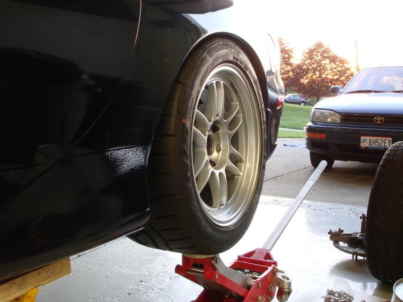
I got my wheels. Enkei RPF1s in 17x9.0 + 45 front, and 17x9.5 +38 rear. I have Falken Azenis RT-615s to put on them, in 255/40/17 front, and 275/40/17 rear.
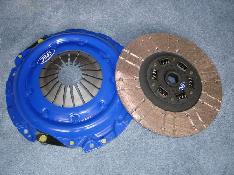
I got my SPEC stage 3+ clutch this week. Looks nice.
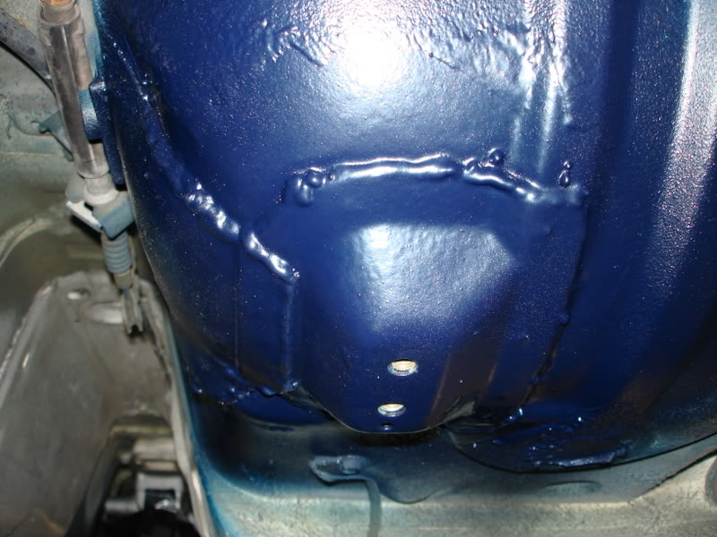
I pulled the rear subframe and things to do some painting and welding. I welded the body mounts for the diff cross member. I fully welded around the seam, and then primed, underbody coated, and sprayed with Montego Blue.
I also made a bracket to mount the parking brake cables, since the factory bracket was on the diff.
I also painted the interior of the floorboards where I welded the plates in for the trans cross member.
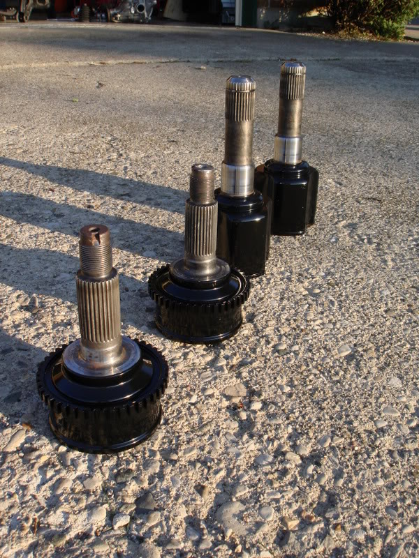
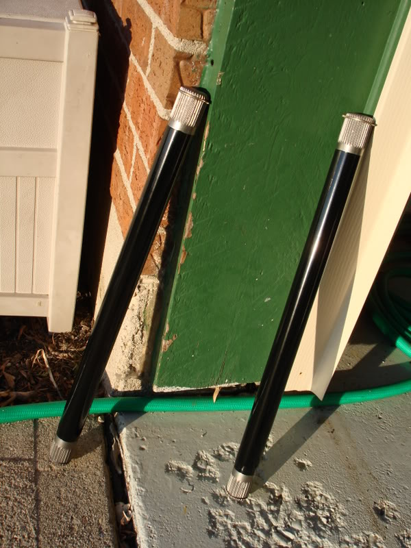
I painted my axle parts, both joint housings, and the actual axle itself. The axles are custom from The Driveshaft Shop.
Some better pics of the modified rear subframe while it was out.
Over the past few days I've been working on chassis wiring.
So far I've just been stripping wires out that I won't need from the engine bay body harness.
I've removed:
Both fuel pump relays and associated wiring
Fuel pump resistor and associated wiring
EGI relay and associated wiring
All 4 fan relays and associated wiring
Air pump relay and associated wiring
A/C relay and associated wiring
Cruise control and associated wiring
Data Link connector and wiring
MAP sensor wiring
Both yellow stock ECU harness plugs
I swear wiring of this magnitude gives me nightmares. Here is the pile of wire removed so far.
Well I missed my self-imposed March deadline, and it looks like I’ll overshoot it by quite a bit. I’ve been doing a bunch of random things on the car recently.
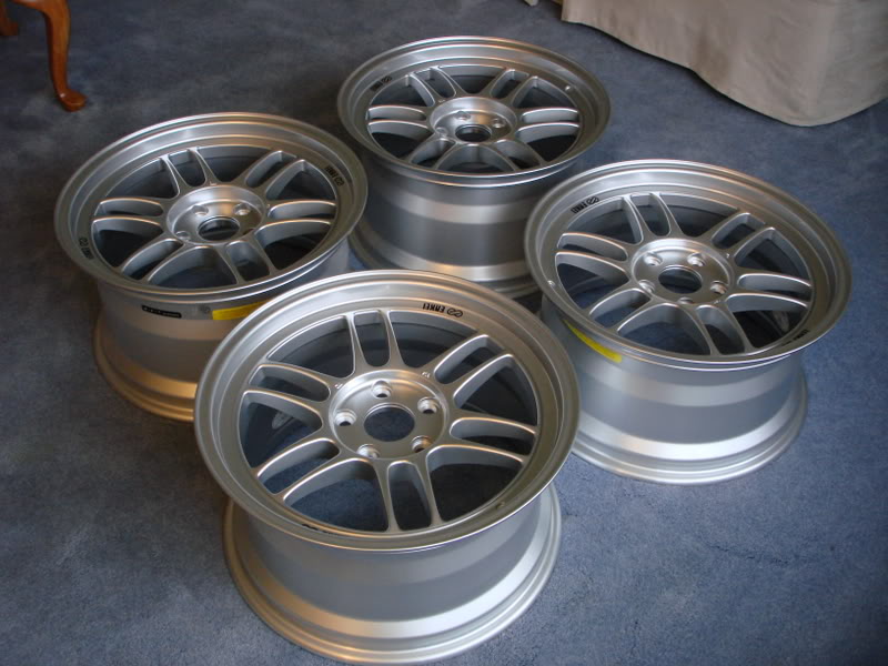
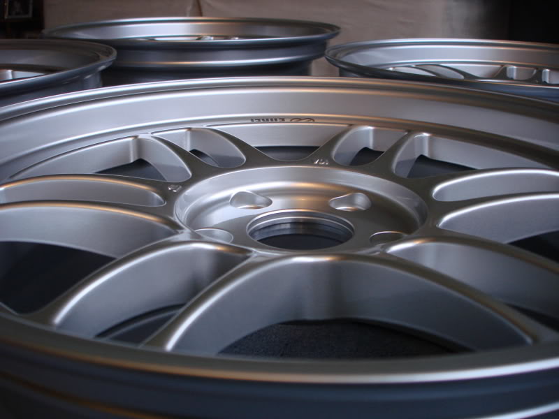
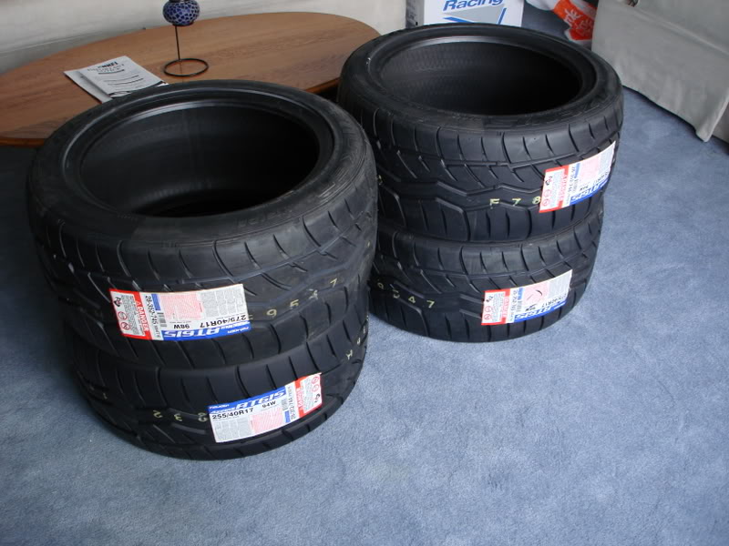
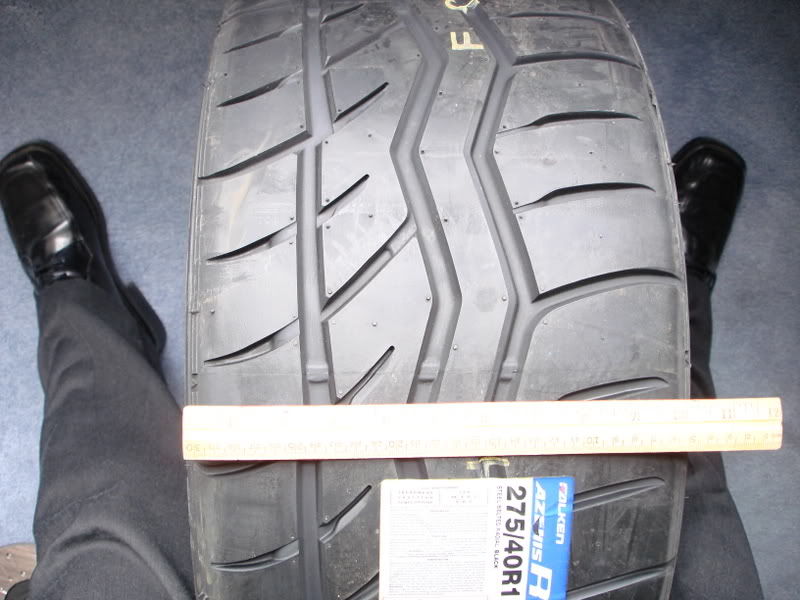
I got my wheels. Enkei RPF1s in 17x9.0 + 45 front, and 17x9.5 +38 rear. I have Falken Azenis RT-615s to put on them, in 255/40/17 front, and 275/40/17 rear.
I got my SPEC stage 3+ clutch this week. Looks nice.
I pulled the rear subframe and things to do some painting and welding. I welded the body mounts for the diff cross member. I fully welded around the seam, and then primed, underbody coated, and sprayed with Montego Blue.
I also made a bracket to mount the parking brake cables, since the factory bracket was on the diff.
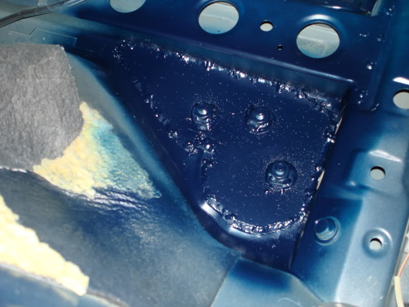
I also painted the interior of the floorboards where I welded the plates in for the trans cross member.
I painted my axle parts, both joint housings, and the actual axle itself. The axles are custom from The Driveshaft Shop.
Some better pics of the modified rear subframe while it was out.
05-20-10, 09:07 AM
#10
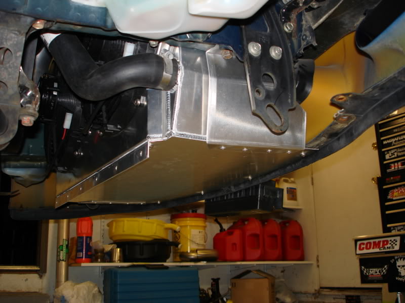
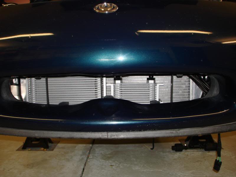
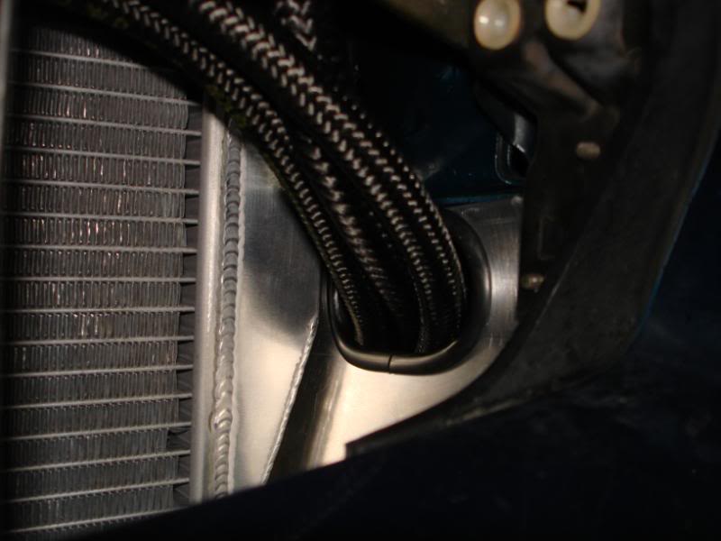
I halfway mounted the radiator. I had to slightly massage the insides of the frame rails with a mallet to get the radiator to fit. The radiator was 28" wide, and the frame rails were exactly 28" between them. I have 1/8" of clearance on each side now.
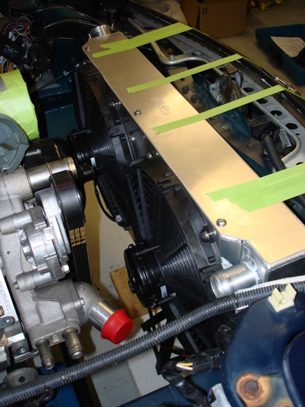
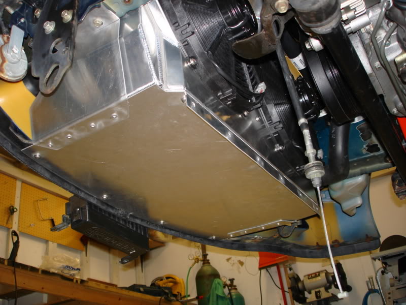
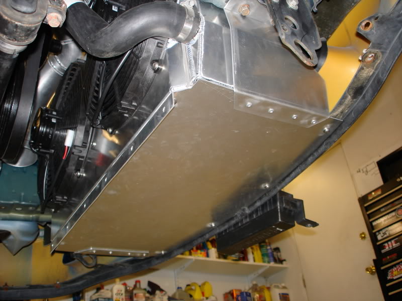
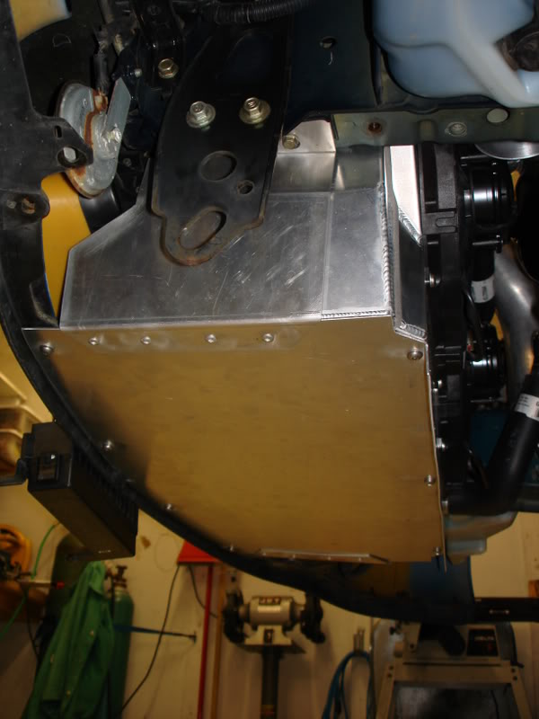
I wanted to isolate the radiator from chassis flex, to ensure a long life for the radiator. What I had to do was weld tabs (angle aluminum) to the side of the tanks. Then I drilled and tapped those tabs for a 8mm bolt. The bolt is used as a locating pin. I drilled some large holes in the tops of the frame rails. Then I used a rubber bushing to insert into the holes. Then the locating pins (bolts) fit right into those holes. It’s a very factory like installation. To keep the radiator from tipping forward/backward I’m going to be using shroud. There will be an aluminum sheet that covers entire space forward of the radiator. It serves the purpose of mounting the top of the radiator, and directing air through the radiator instead of around it. I’m also planning on making a belly pan, or whatever you call it. Its going to go from the front edge of the bumper cover, and extend to at least to the radiator. This will also function to direct all the air entering the bumper, through the radiator.
I just made the upper fan mount/shroud. It doesn't have all the bolts holding it down yet, I need to get some longer bolts and spacers for some of the holes.
 05-20-10, 09:08 AM
#11
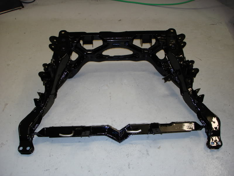
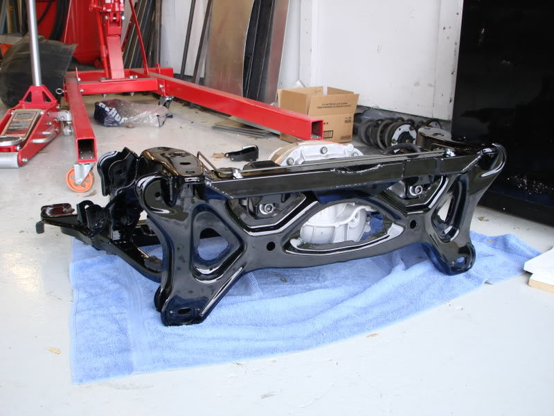
Got my subframe back from the paint guy (Dale - t2fastalon). I did some welding for him in exchange for the paint on the rear subframe and crossmember. He did an excellent job on it, especially considering the difficulty of the part.
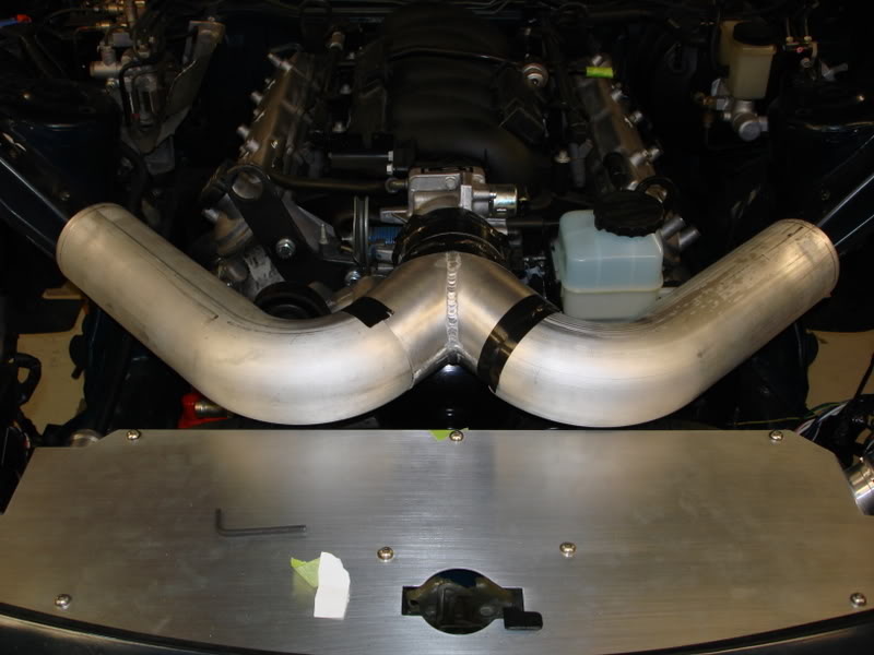
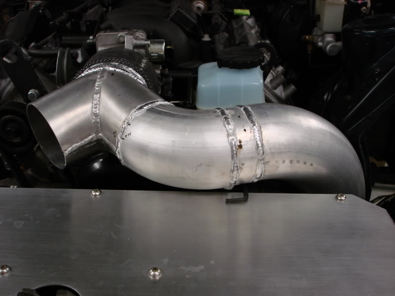
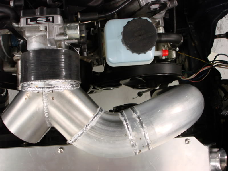
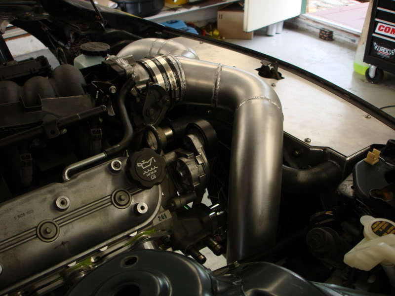
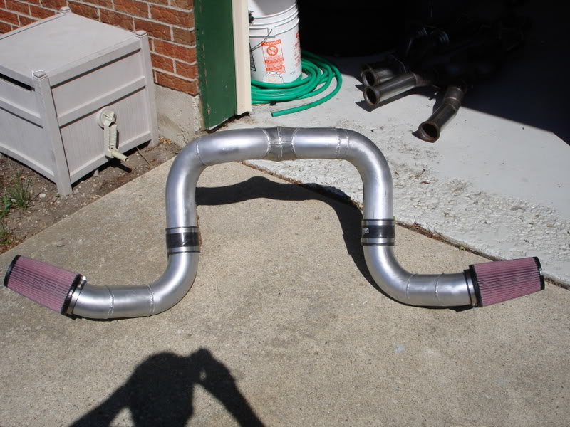
Getting started on my dual intake pipes. I'm going from the throttole body, which is 4", to a dual 3.5" setup, with a filter in each bumper cover opening.
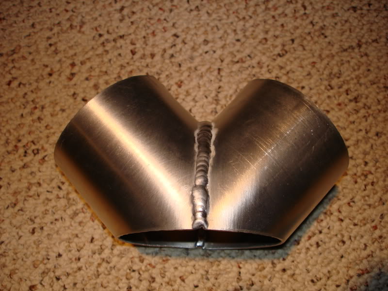
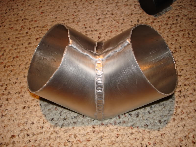
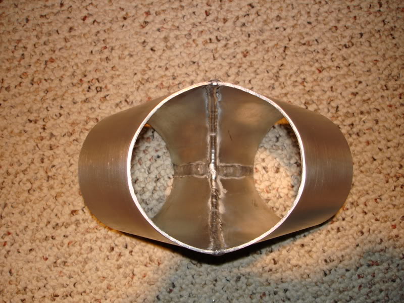
This fitting was a total ************ to make. Getting the 4" fitting both planar, and round took forever. It was built from sheetmetal. Turned out pretty nice. out of practice, but its comming along nicely. Its been a while since I've welded aluminum, so I'm a bit oth the inside and outside to make it nice and smooth.
On the big end I plan to weld on a 12ish degree 4" elbow. On the small ends I plan on welding a 45 degree elbow to make a complete 90 degree bend, then go from there.
In case you totally don't understnad what I"m talking about doing, here are some pics of the beginning of the intake. Note: The long straight portions on each end will be cut off, this is jus the beginning till I get some more elbows in the mail.
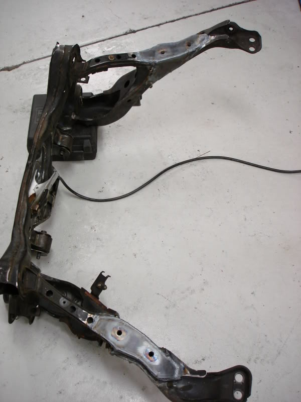
My subframe is all assembled, ready to install. Yea!!!
 05-20-10, 09:09 AM
#12
Well amist all my wedding stuff, I was able to get some work done on the car this weekend. I got the rear subframe assembly installed in the car for the final time. Everything fit up perfect and the install was a cinch.
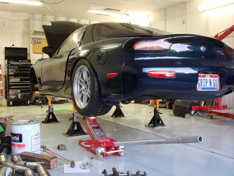
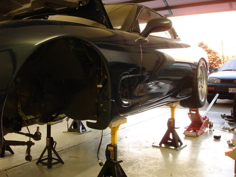
I put on one side of the rear suspension and a wheel, to determine where I want to drill my control arms for zerk fittings for the greaseable delrin bushings I have. I also did some test fitting of my wheels. I had no shock/strut installed, so I just jacked up the wheel to the desired height of 25" from the ground to the fender lip. It appears that at that ride height I'll need some fender rolling.
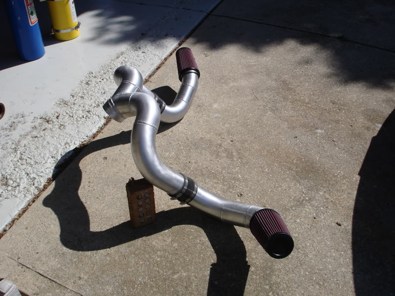
Got started on the my dual intake setup a little bit. Ended up getting the drivers side about halfway done. Welding the aluminum elbows was kinda tough on the outside of the bend because the material is so thin from the bending process. So far its welding pretty good. Could be better, but its sufficient.
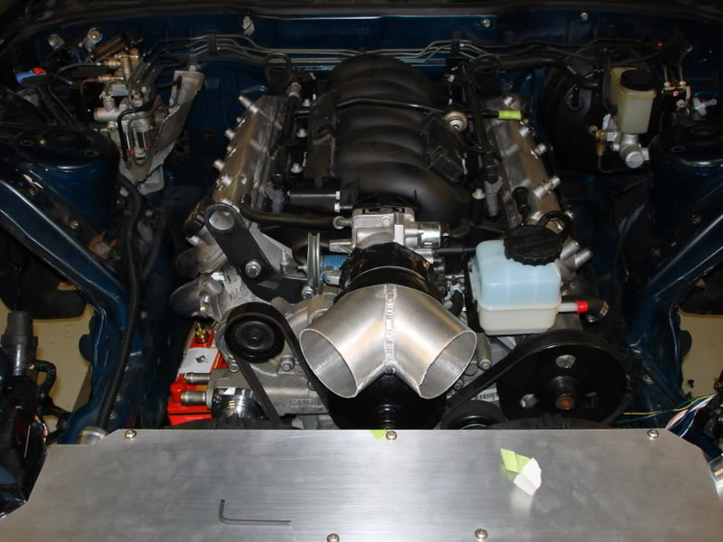
Got my upper intake pipes done. Now I just need to get the lower part finsihed and get the filters behind the bumper cover openings.
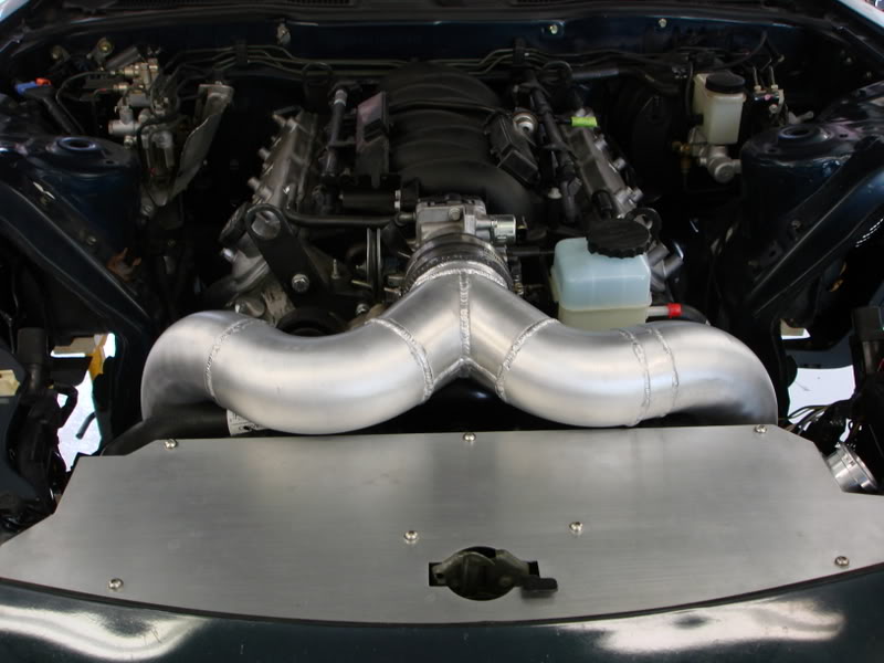
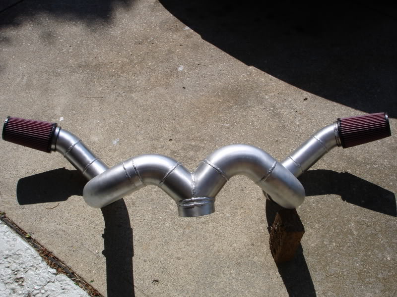
I finilized my intake setup today. I've placed the filters right behind the side openings in the bumper cover. I feel that will be the best way to get maximum air into the engine, regardless of looks. I might call K&N and see if I can put some black dye in their oil to so they don't stand out as much.
I believe this might actually almost the end of fabrication on this project. I must say, I am very relieved at this fact. The build has been extremely time consuming thus far, and I'll be happy to focus on getting the last few things plumbed up, and wiring completed.
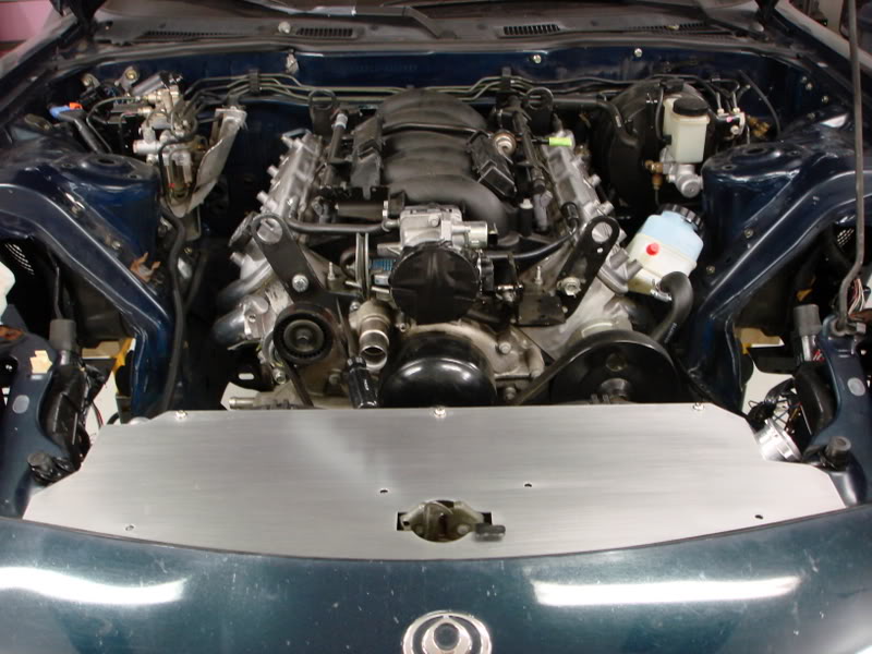
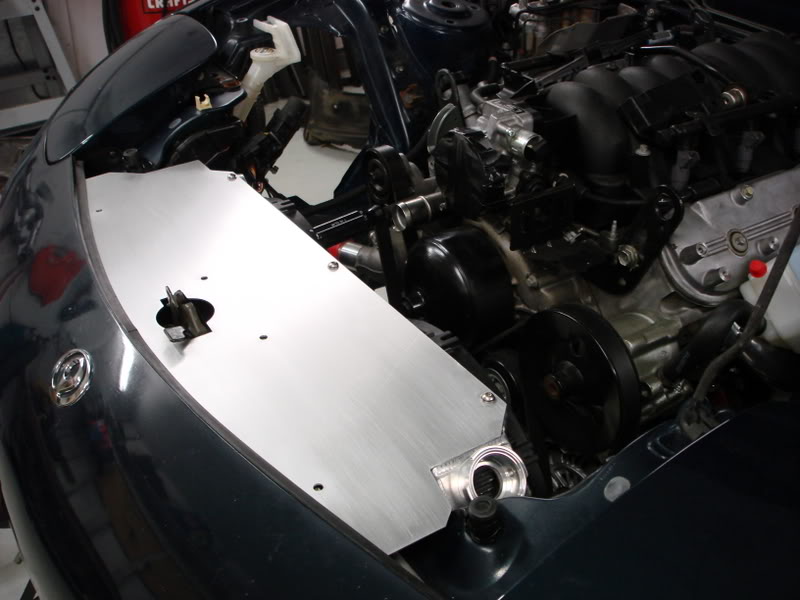
Tonight I nearly finished my lower radiator shroud. Now the radiator is completly boxed in from the front. This will cause all the air that enters the bumper cover to travel through the radiator, for good cooling. The only thing left to do is put a rubber strip on the back edge. On the 1" turned down edge, I will be attaching a 1/4" thick, 3" tall piece of rubber. This should create a lower pressure area behind the radiator for improved cooling flow.
I put on one side of the rear suspension and a wheel, to determine where I want to drill my control arms for zerk fittings for the greaseable delrin bushings I have. I also did some test fitting of my wheels. I had no shock/strut installed, so I just jacked up the wheel to the desired height of 25" from the ground to the fender lip. It appears that at that ride height I'll need some fender rolling.
Got started on the my dual intake setup a little bit. Ended up getting the drivers side about halfway done. Welding the aluminum elbows was kinda tough on the outside of the bend because the material is so thin from the bending process. So far its welding pretty good. Could be better, but its sufficient.
Got my upper intake pipes done. Now I just need to get the lower part finsihed and get the filters behind the bumper cover openings.
I finilized my intake setup today. I've placed the filters right behind the side openings in the bumper cover. I feel that will be the best way to get maximum air into the engine, regardless of looks. I might call K&N and see if I can put some black dye in their oil to so they don't stand out as much.
I believe this might actually almost the end of fabrication on this project. I must say, I am very relieved at this fact. The build has been extremely time consuming thus far, and I'll be happy to focus on getting the last few things plumbed up, and wiring completed.
Tonight I nearly finished my lower radiator shroud. Now the radiator is completly boxed in from the front. This will cause all the air that enters the bumper cover to travel through the radiator, for good cooling. The only thing left to do is put a rubber strip on the back edge. On the 1" turned down edge, I will be attaching a 1/4" thick, 3" tall piece of rubber. This should create a lower pressure area behind the radiator for improved cooling flow.
05-20-10, 09:09 AM
#13
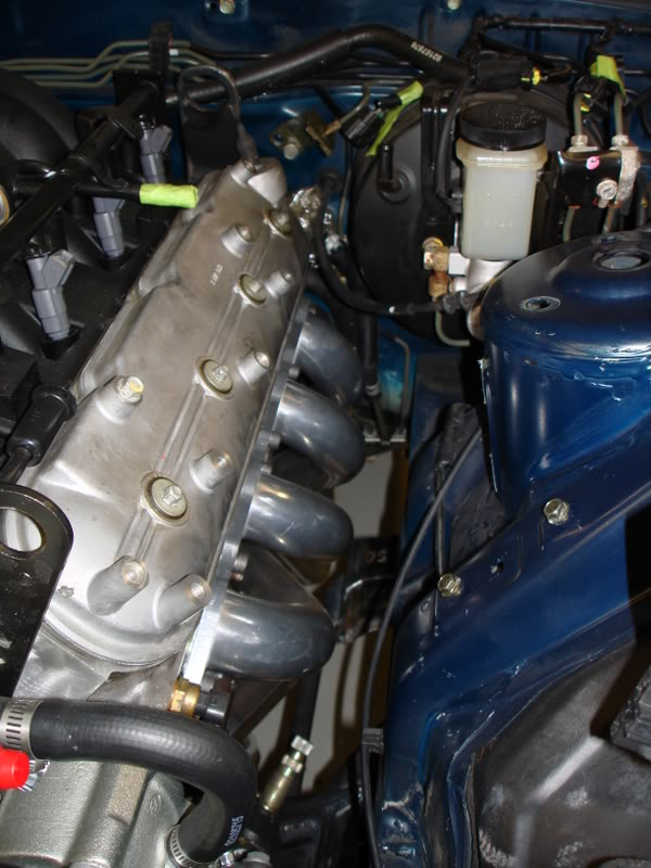
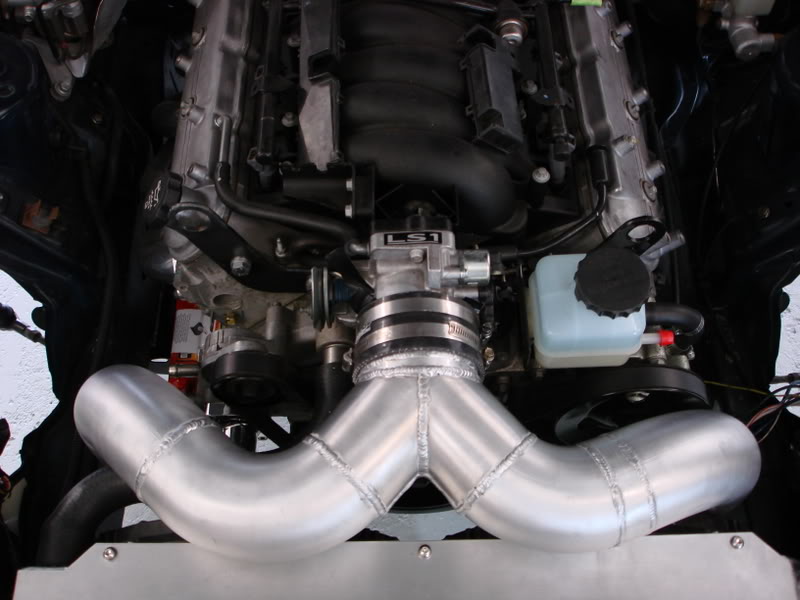
I finished up my intake piping. I think it should flow really well. Still unsure of where I'll put my IAT sensor at the moment.
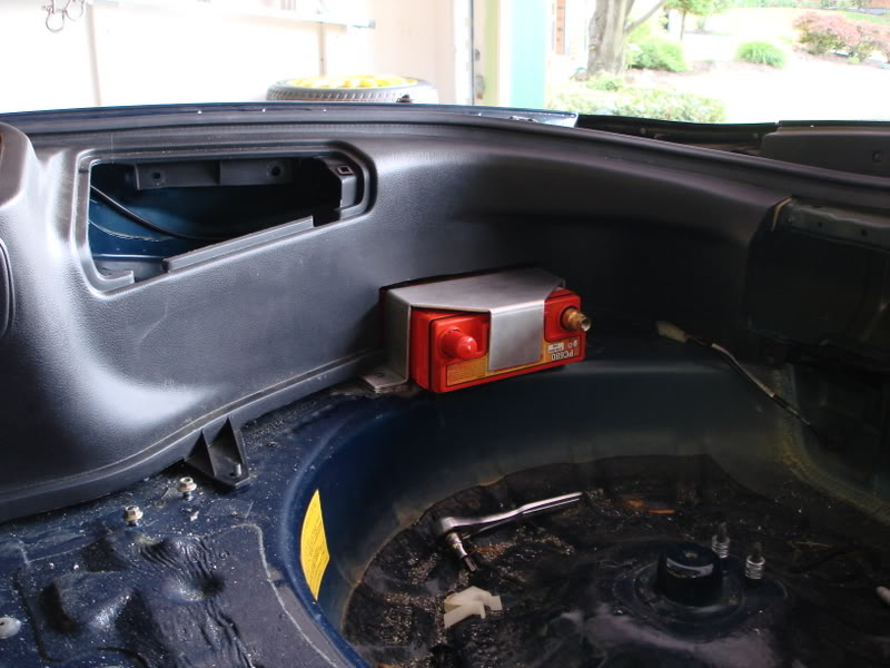
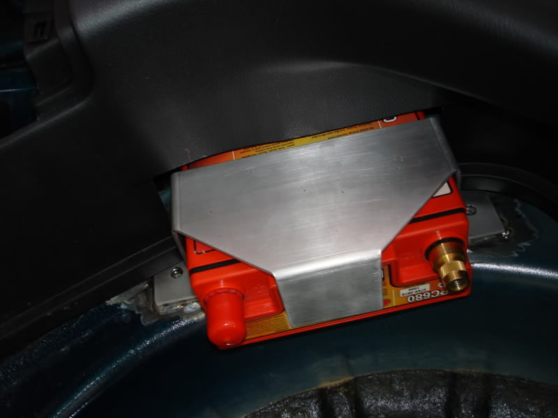
I also mounted my battery. I decided to put it on the opposite side of the gas tank and driver to try and balance out the weight some (that and it fit well there). Its an Odyssey PC680MJT.
Well I got married a month ago, then went on a honeymoon, which was great. Then came back from a great week in Maui to a flooded basement. A fitting on my toilet had cracked and leaked for a solid week, thus soaking the carpet and padding beneath. I've been working on getting that back in order, and going much needed yard work, so the car was put on the back burner for a few weeks.
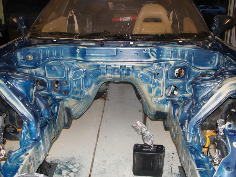
Well I'm back at it now. I made a few fuel lines up, nothing too fancy, and no pics of them yet. Dale has my front subframe and tranny crossmember for a quality paint job. Then I removed every last thing from my engine bay to prep for paint. The paint in the engine bay wasn't the best, and the factory coverage left some to be desired. I have the bay all prepped and ready for paint now (well, as least to my knowledge, Dale will tell me if its good enough).
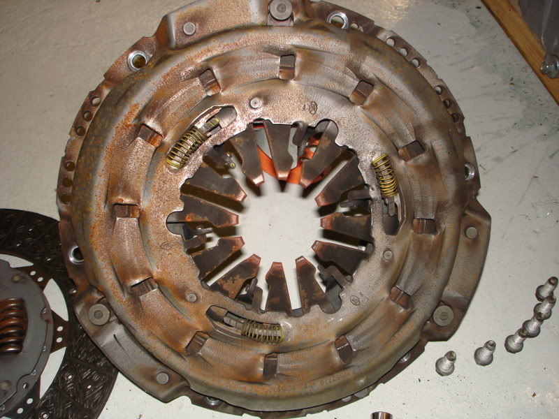
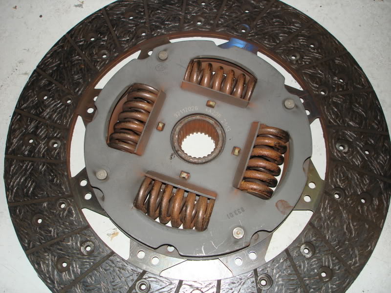
I also removed the clutch on the 14k mile GTO engine. I'm not sure that the clutch is stock. There are still machining ridges on both the pressure plate and the flywheel, adn there is very little dust inside the bellhousing. The clutch disc also looks to have little to no wear. Anyone know if this is a stock 2004 GTO clutch? It says LUK on it stamped in a few places.
 05-20-10, 09:10 AM
#14
Much more to come soon. The clutch line, power steering line, and fuel lines should be finished up soon.
Finally, some progress that is picture worthy. Its been a while since thats happened.
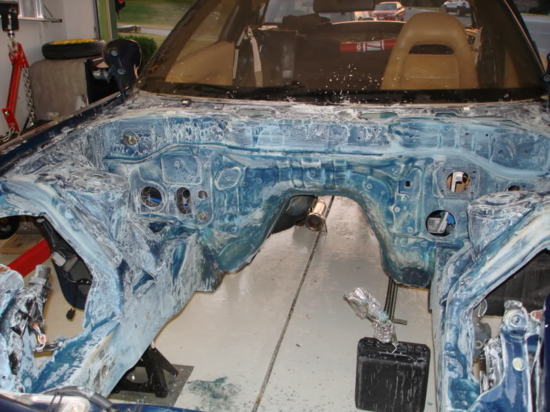
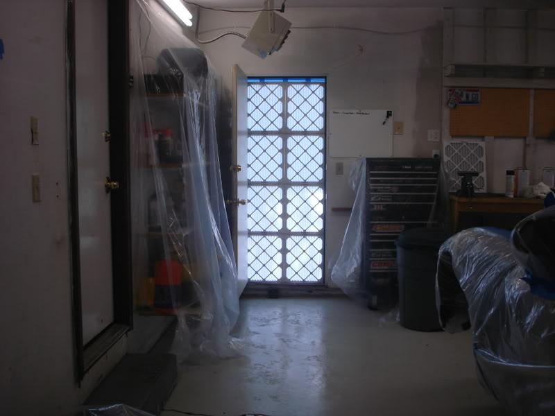
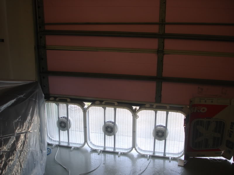
I turned my garage into a paintbooth as best as I could. I took probalby 4 days to remove all the metal dust from the fab I've been doing, and once that was gone I mopped the floor 3 times to ensure it was a dust free environment. I made an air filter insert for my back door of the garage, all out of home HVAC filters. That was the intake for the garage. For exhaust I bought three box fans and tied them together. I cracked my garage door enough to fit the fans underneath, then covered the rest of the gap with cardboard. I tapped the cardboard down, and sealed up any other possible air leaks w/o going way overboard. This worked really well to remove the fumes and overspray. Surprisingly well actually.
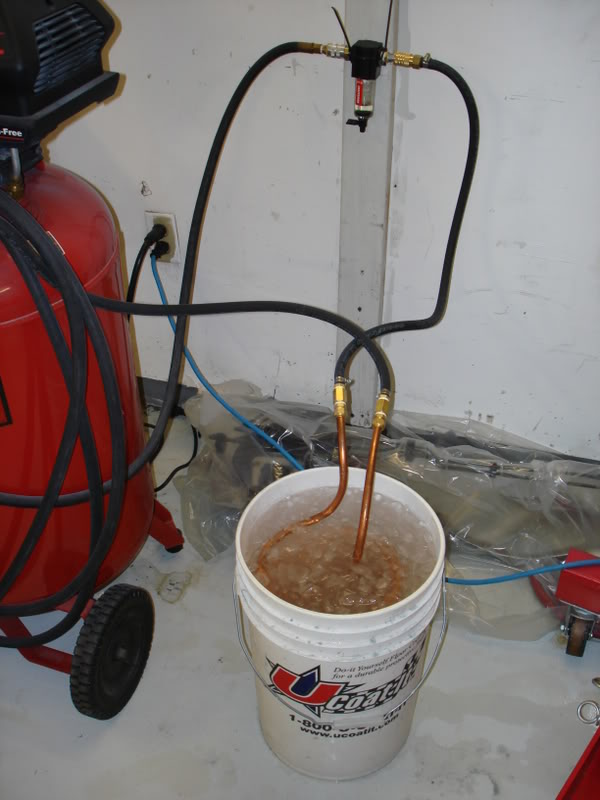
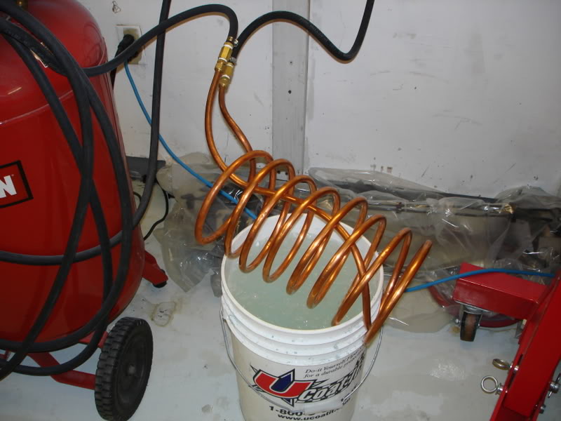
Then I needed to get my air supply in order. My painter (Dale, t2fastalon, if your reading this on a local forum) told me that my compressor should flow enough to keep up well with his HVLP spray gun. To ensure a dry air source I did a bit of research and came up with a fairly cheap solution. I purchased a craftsman water trap to put inline, however, those only pick up liquid water, not water vapor or moisture in the air. So I made a homemade air dryer. Its a 20' piece of 1/2" coiled copper. I submersed it in ice water. The idea here is to remove the moisture from the air traveling through the coil. The moist air condenses on the cold walls of the copper tubing in the ice water, then turns into liquid water. I put the air dryer right before the water trap, so the water trap could pick up all the condensate. This worked great, today was not a humid day in the least bit, but I still managed to pull out a complete bottle full of water out of the water trap. Again, I was amazed with how well it worked.
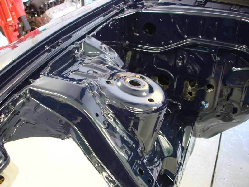
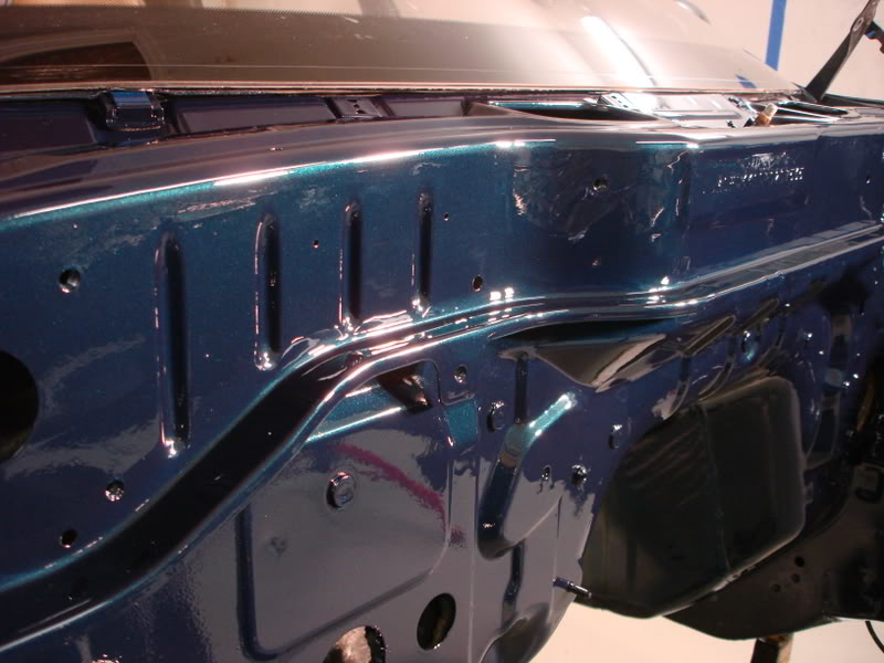
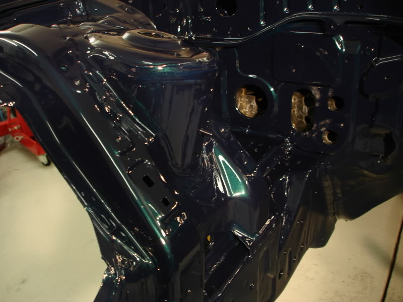
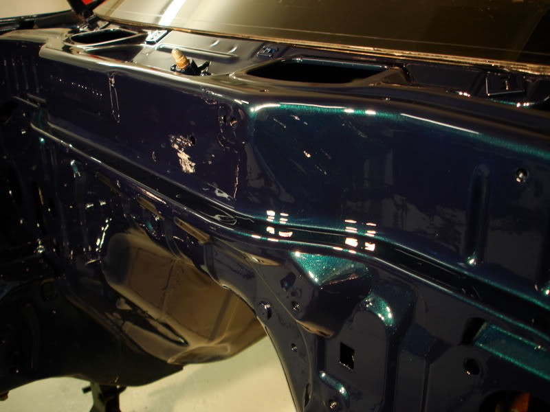
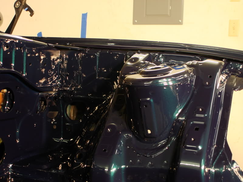
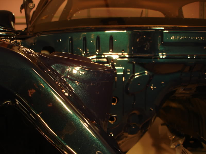
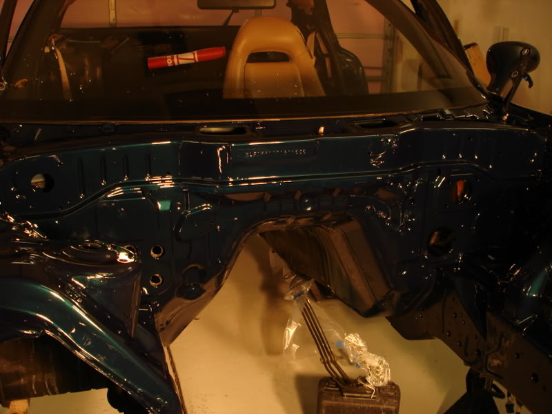
Now the pics......
Here is some of Dale putting on the base coat.
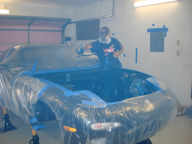
A few pics after the base coat, but before the clear.
And for the pics after the clear has dried. To help dry the paint, I attempted to bake the paint with my heater. I was able to get it up to 115 degrees, and left it there for 2.5 hours. Then I took these pics. I'm very happy with how it turned out. A big thanks goes out to Dale for doing such a great job! Thanks Dale!
Finally, some progress that is picture worthy. Its been a while since thats happened.
I turned my garage into a paintbooth as best as I could. I took probalby 4 days to remove all the metal dust from the fab I've been doing, and once that was gone I mopped the floor 3 times to ensure it was a dust free environment. I made an air filter insert for my back door of the garage, all out of home HVAC filters. That was the intake for the garage. For exhaust I bought three box fans and tied them together. I cracked my garage door enough to fit the fans underneath, then covered the rest of the gap with cardboard. I tapped the cardboard down, and sealed up any other possible air leaks w/o going way overboard. This worked really well to remove the fumes and overspray. Surprisingly well actually.
Then I needed to get my air supply in order. My painter (Dale, t2fastalon, if your reading this on a local forum) told me that my compressor should flow enough to keep up well with his HVLP spray gun. To ensure a dry air source I did a bit of research and came up with a fairly cheap solution. I purchased a craftsman water trap to put inline, however, those only pick up liquid water, not water vapor or moisture in the air. So I made a homemade air dryer. Its a 20' piece of 1/2" coiled copper. I submersed it in ice water. The idea here is to remove the moisture from the air traveling through the coil. The moist air condenses on the cold walls of the copper tubing in the ice water, then turns into liquid water. I put the air dryer right before the water trap, so the water trap could pick up all the condensate. This worked great, today was not a humid day in the least bit, but I still managed to pull out a complete bottle full of water out of the water trap. Again, I was amazed with how well it worked.
Now the pics......
Here is some of Dale putting on the base coat.
A few pics after the base coat, but before the clear.
And for the pics after the clear has dried. To help dry the paint, I attempted to bake the paint with my heater. I was able to get it up to 115 degrees, and left it there for 2.5 hours. Then I took these pics. I'm very happy with how it turned out. A big thanks goes out to Dale for doing such a great job! Thanks Dale!
05-20-10, 09:11 AM
#15
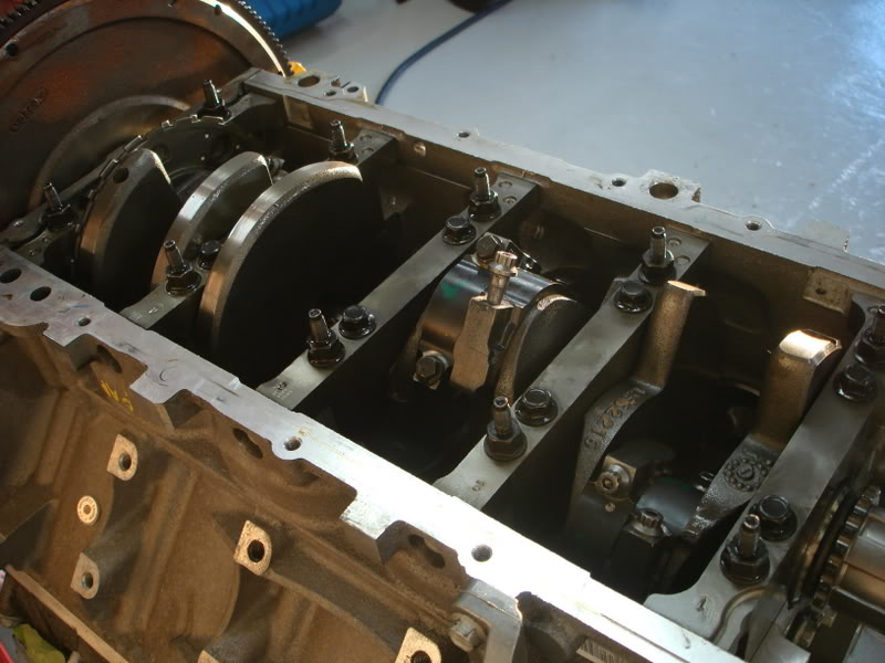
I finally tore my motor apart to install the new parts. The LS1 motor is all new to me, pushrod motors in general really. I really never understood how they worked till I took it apart and saw for myself. Pretty simple really.
First thing I did was remove the oil pan. I take the pan off, flip it over and this is what i see. Something is definately wrong here.
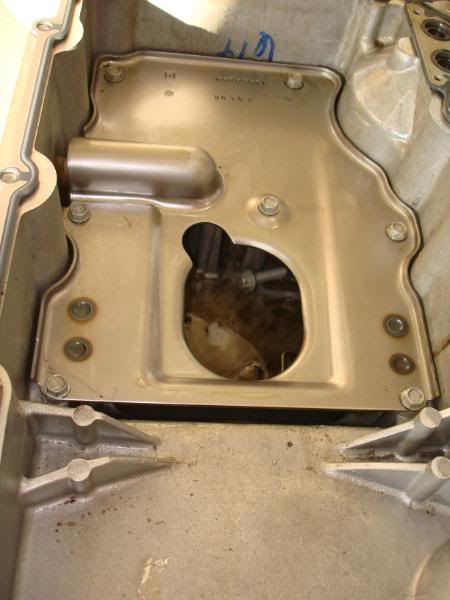
I'm definately going to have a talk with the place I bought the motor from. They switched the pan, pickup, and windage tray to that of a F-body, from the GTO setup. The GTO is front sump, the F-body is rear sump. Aparently some douche dropped a bolt in the pan before they put it together. ASE certification, aparently that doens't mean too much.
Then I started removeing parts. I removed the timing cover and valve covers.
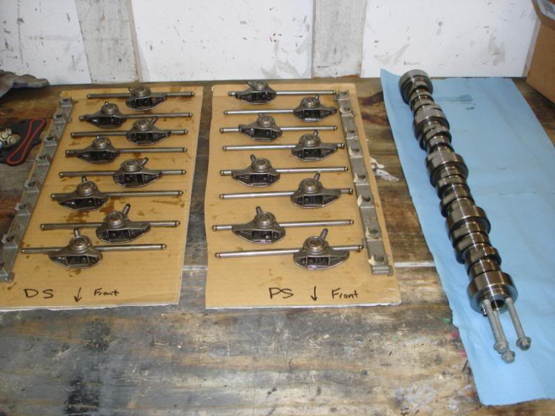
Then I removed the rockers, pushrods, and cam. To remove the cam I didn't use any fancy lifter retaining tool, I just put the motor upsidedown and let gravity do the work for me.
I also put the new cam in, all lubed up and ready to go. Lubing up my bumpstick was fun.
Should have the rest of my parts in a few days.
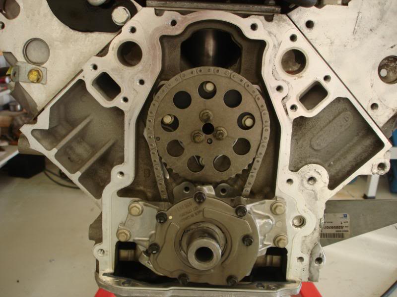
I got the cam in, put the cam retainer plate on, and torqued it all down. Then I took off the windage tray and put in my ARP rod bolts one by one. You have to torque them down three times to 40 ft-lbs. I put those in, then put the windage tray back on. I got the timing chain back on and all lined up as well. Then I put on the ported and shimmed LS6 oil pump. I made sure to pour a shitload of oil in the pump to get it all nice and lubed up. Then I decided to call it a day. I plan on doing the spring swap probably tomorrow.
Only one pic this time. I was in progress of putting the rod bolts in.
I worked some more on my engine tonight. I have PRC dual springs, which are compatible with the high lift of the cam I chose. The kit came with Titanium retainers, spring seats, valve stem seals, and chromoly pushrods.
Here is a comparison picture between the two springs.
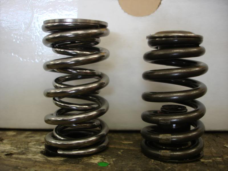
Here I took a picture after doing only two springs, a comparison of springs/retainers installed in the cylinder head.
 05-20-10, 09:12 AM
#16
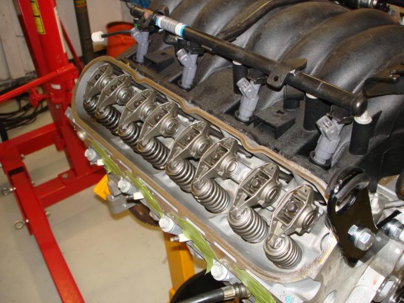
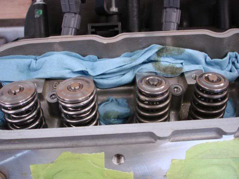
All the springs swapped, it was easy once I got the hang of it and felt more comfortable with doing it. I just put some assembly lube on the pushrods and dropped them in their holes.
Then I put the rockers back on, and got everything torqued down. Everything went pretty smooth once I got a valve spring compressor that worked well with the LS1 and the dual springs I have.
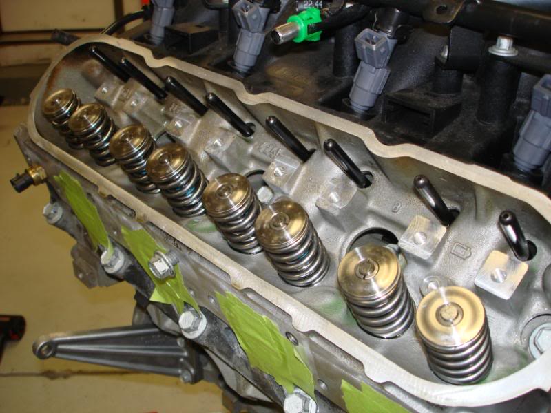
Cam/springs/pushrods/oil pump/rod bolts are all installed. Only thing left to do is put the oil pan back on and the timing chain cover, and the motor will be all buttoned up.
I got the motor all buttoned up. I was delayed because I had to make a crank pulley install tool. I prefered this method over simply using a bolt, as I don't think there would be as much stress on the crank threads (heat from friction and whatnot).
I also installed my front subframe and put in the steering rack to check a few cleanrances.
I finished up my fuel lines today. My fuel system consists of a 255 lph high pressure walbro pump, removed stock fuel filter, stock hard lines (5/16") up to the engine bay. I cut off some of the stock hard lines and used industrial compression fittings, said to be good to 3000 psi. From there I used adapters to go from pipe thread to a male AN -6 fitting. I run a -6 to an Aeromotive fuel filter (10 micron), then to the Aeromotive FPR. From there I run a -6 to the engine and use a quick disconnect fitting on the rail. I also have a -6 plummed for the return.
All these components can accept a -10 fitting, so upgrading the fuel system will be as simple as running larger lines, the filter and FPR can stay in the same location.
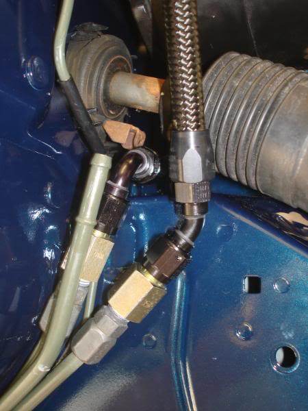
The return line I ran under the steering column and as the shaft turns, I have 1/4" clearance at the tightest portion of its rotation.
I had to rework part of the stock hard lines to move them further away from the header pipes. Before I reworked them I had maybe 1" of cleanrance between of them, and now I have increased that cleanrance to probalby 3". And for some pics as always.
Overall shot:

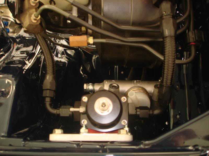
Closeup of filter and regulator:
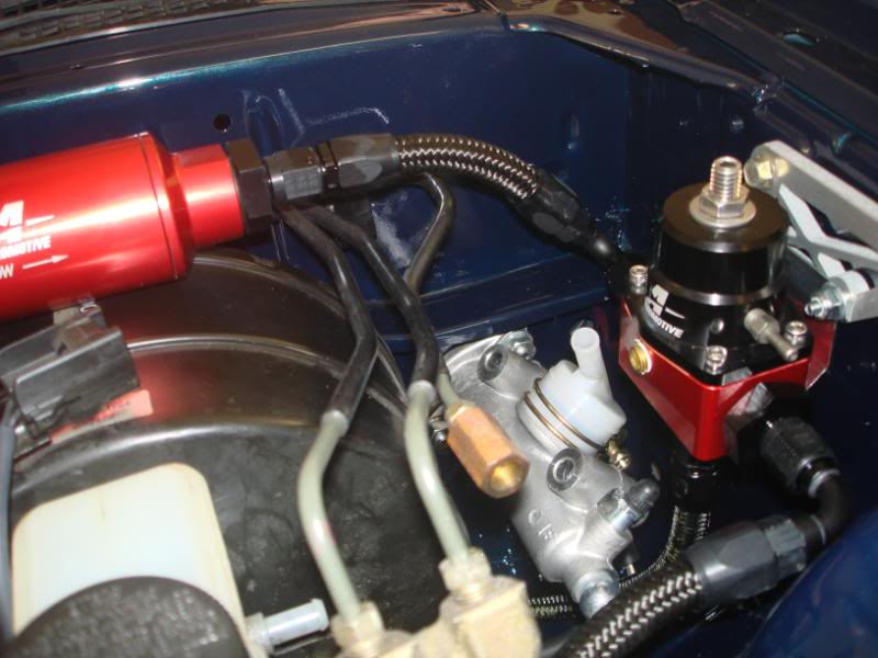
Top view:
Threading the needle. Running the line under the steerin column.
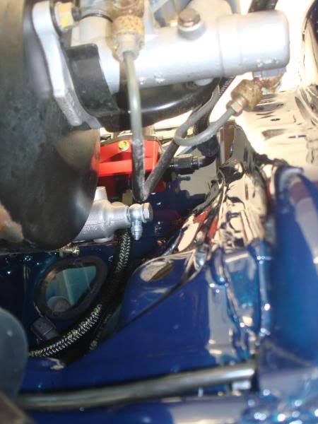
And a funny looking shot lookin up at the bottom of the regulator to see routing of the return line.
I can't really say when it will be done, I'm busting *** so whenever it ends up being done. I'm definately on the final stretch I'd say.
Small progress, but any progress at this point is good. I've been getting bogged down lately with lifes other adventures.
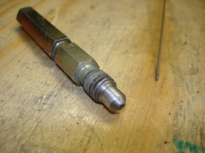
Anyhow, I finally decided what I'm planning on doing for a clutch line. I'll be using -3 line and fittings. The bleeder screw (long piece pictured) would be hard to reach in the car, so I decided I'd make a remote bleeder. Here are some modifications that I've done in order to acheive this. I drilled a hole in the tip of hte bleeder screws, so fluid can always pass through the old bleeder screw, even when tightened.
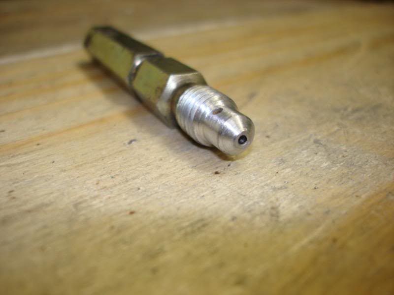
Then I realized that the small hole on the side of the bleeder would allow fluid to pass through it, and leak out the threads. So I welded the hole shut and filed it down by hand. Now the fluid can only pass through the shaft of the old bleeder.
Then I put the rockers back on, and got everything torqued down. Everything went pretty smooth once I got a valve spring compressor that worked well with the LS1 and the dual springs I have.
Cam/springs/pushrods/oil pump/rod bolts are all installed. Only thing left to do is put the oil pan back on and the timing chain cover, and the motor will be all buttoned up.
I got the motor all buttoned up. I was delayed because I had to make a crank pulley install tool. I prefered this method over simply using a bolt, as I don't think there would be as much stress on the crank threads (heat from friction and whatnot).
I also installed my front subframe and put in the steering rack to check a few cleanrances.
I finished up my fuel lines today. My fuel system consists of a 255 lph high pressure walbro pump, removed stock fuel filter, stock hard lines (5/16") up to the engine bay. I cut off some of the stock hard lines and used industrial compression fittings, said to be good to 3000 psi. From there I used adapters to go from pipe thread to a male AN -6 fitting. I run a -6 to an Aeromotive fuel filter (10 micron), then to the Aeromotive FPR. From there I run a -6 to the engine and use a quick disconnect fitting on the rail. I also have a -6 plummed for the return.
All these components can accept a -10 fitting, so upgrading the fuel system will be as simple as running larger lines, the filter and FPR can stay in the same location.
The return line I ran under the steering column and as the shaft turns, I have 1/4" clearance at the tightest portion of its rotation.
I had to rework part of the stock hard lines to move them further away from the header pipes. Before I reworked them I had maybe 1" of cleanrance between of them, and now I have increased that cleanrance to probalby 3". And for some pics as always.
Overall shot:
Closeup of filter and regulator:
Top view:
Threading the needle. Running the line under the steerin column.
And a funny looking shot lookin up at the bottom of the regulator to see routing of the return line.
I can't really say when it will be done, I'm busting *** so whenever it ends up being done. I'm definately on the final stretch I'd say.
Small progress, but any progress at this point is good. I've been getting bogged down lately with lifes other adventures.
Anyhow, I finally decided what I'm planning on doing for a clutch line. I'll be using -3 line and fittings. The bleeder screw (long piece pictured) would be hard to reach in the car, so I decided I'd make a remote bleeder. Here are some modifications that I've done in order to acheive this. I drilled a hole in the tip of hte bleeder screws, so fluid can always pass through the old bleeder screw, even when tightened.
Then I realized that the small hole on the side of the bleeder would allow fluid to pass through it, and leak out the threads. So I welded the hole shut and filed it down by hand. Now the fluid can only pass through the shaft of the old bleeder.
05-20-10, 09:12 AM
#17
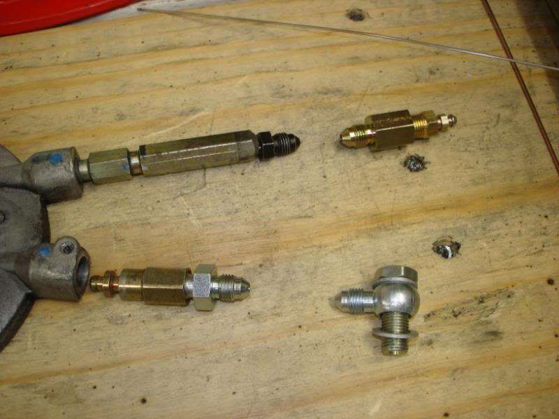
From there, I'll be connecting a flex line (-3 AN) to a remote bleeder. For the pressure side I'll be connecting to the clutch master cylinder wiht a banjo bolt and a -3 fitting. I'll run a -3 flex line to the pressure side of the slave cylinder. I need to extend the pressure side fitting to be the same length as the old bleeder. This should allow me to disconnect it with the tranny still installed on the vehicle.
I was having a hard time deciding between -3 and -4 sized line, and ended up choosing -3 because that is what the OEM hard line most closly relates to. If anyone has any reason -4 would be better, please let me know asap. I don't have any experience with custom clutch pressure lines.
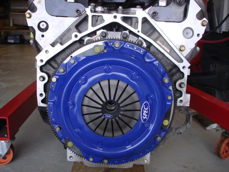
I installed my SPEC 3+ clutch, and fidanza flywheel.
I had to put the engine back in for maybe the final mock-up, to get clutch lines made. I wanted to put it in with the header on and check clearnace on a few things to be sure. Hopefully it will only come out one last time.
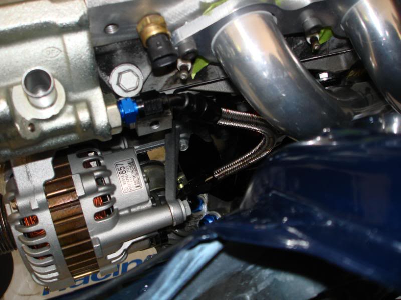
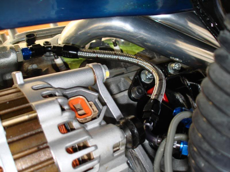
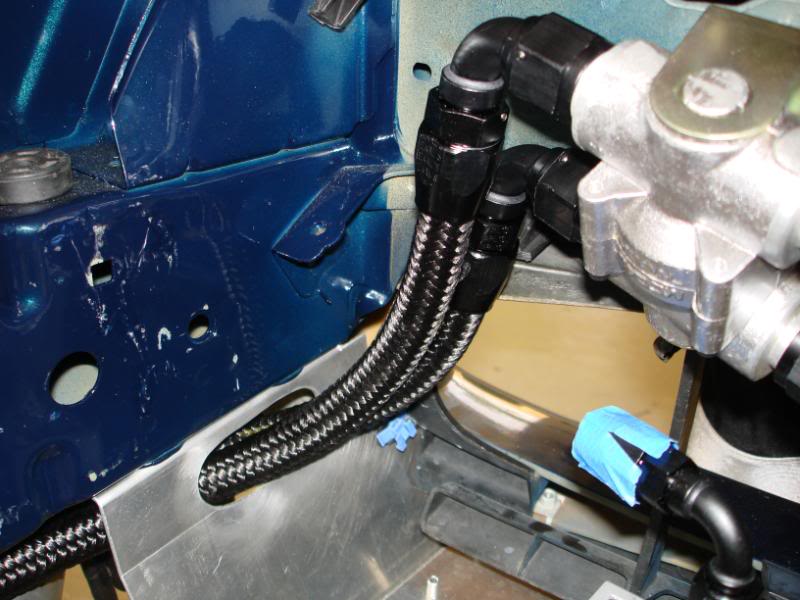
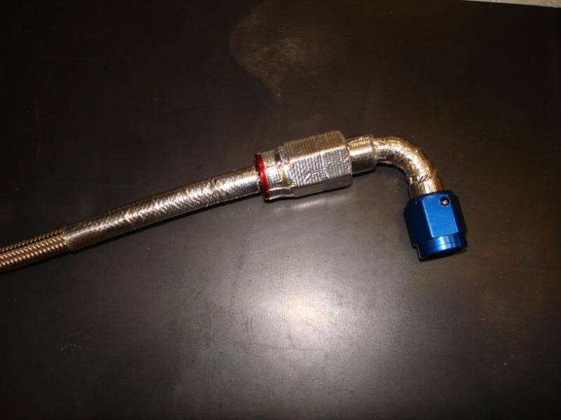
I finished up the power steering pressure line. I went the the braided stainless for this line to handle the high presusre that the host must endure. I was still able to use the black fittings that I like so much. I put in a little extra length to compensate for engine movement and not stress the hose too much.
I made some more progress worth taking pictures of recently.
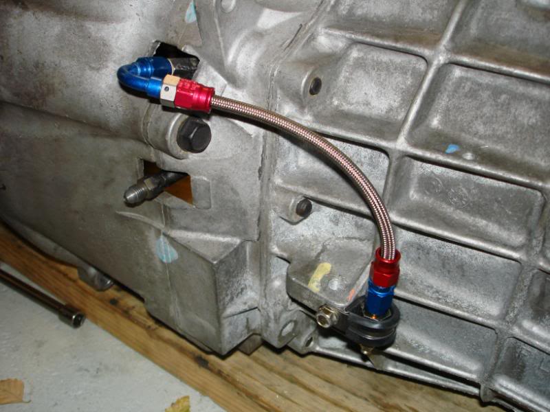
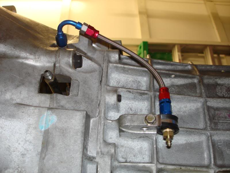
I modified the pressure line and bleeder line on the clutch slave cylinder. I extended the stock feed line so it would exit the bellhousing and I could tighten my AN line to it. I also added -3 male fittings to both the feed and bleeder. I wanted to be able to bleed my clutch easily, so I made a remote bleeder setup.
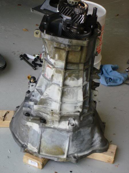
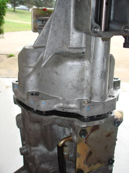
Then I began to disassembly my transmission to fix a leak that I thought was comming from the seam between the transmission case, and the tailshaft housing case.
Here is the nasty underside of my 14k mile GTO trans............(not happy about this)
I was having a hard time deciding between -3 and -4 sized line, and ended up choosing -3 because that is what the OEM hard line most closly relates to. If anyone has any reason -4 would be better, please let me know asap. I don't have any experience with custom clutch pressure lines.
I installed my SPEC 3+ clutch, and fidanza flywheel.
I had to put the engine back in for maybe the final mock-up, to get clutch lines made. I wanted to put it in with the header on and check clearnace on a few things to be sure. Hopefully it will only come out one last time.
I finished up the power steering pressure line. I went the the braided stainless for this line to handle the high presusre that the host must endure. I was still able to use the black fittings that I like so much. I put in a little extra length to compensate for engine movement and not stress the hose too much.
I made some more progress worth taking pictures of recently.
I modified the pressure line and bleeder line on the clutch slave cylinder. I extended the stock feed line so it would exit the bellhousing and I could tighten my AN line to it. I also added -3 male fittings to both the feed and bleeder. I wanted to be able to bleed my clutch easily, so I made a remote bleeder setup.
Then I began to disassembly my transmission to fix a leak that I thought was comming from the seam between the transmission case, and the tailshaft housing case.
Here is the nasty underside of my 14k mile GTO trans............(not happy about this)
05-20-10, 09:14 AM
#18
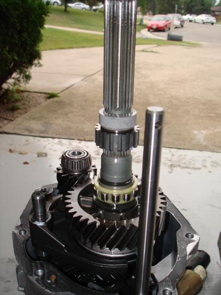
So I removed the rear case, here are some pics of that.
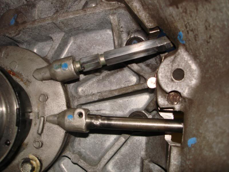
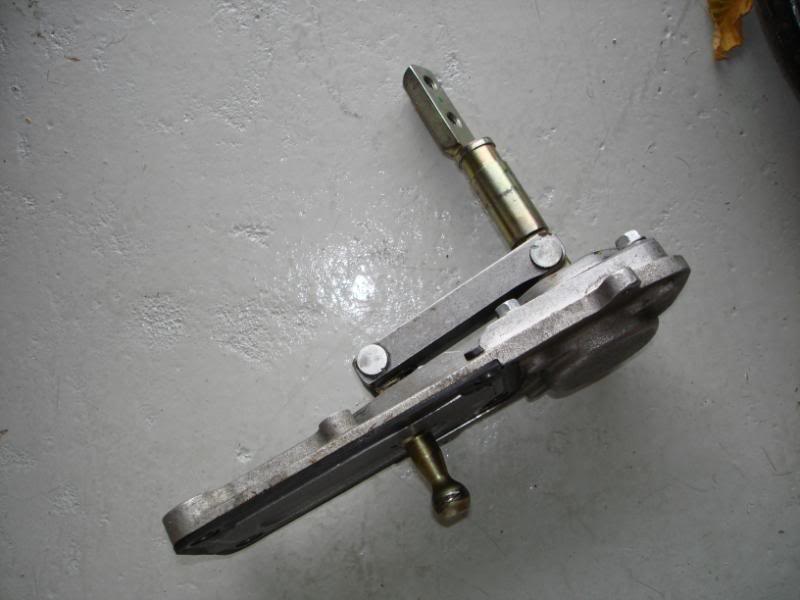
The GTO shifter plate that moves the shifter input rearward.

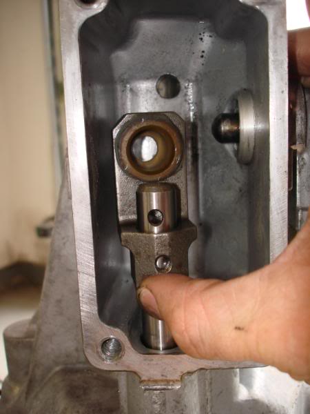
Then I removed this piece, can't recall the name of it right now.
Then cracked the case loose.
Then pulled the case and here are some pics of the insides of the trans.
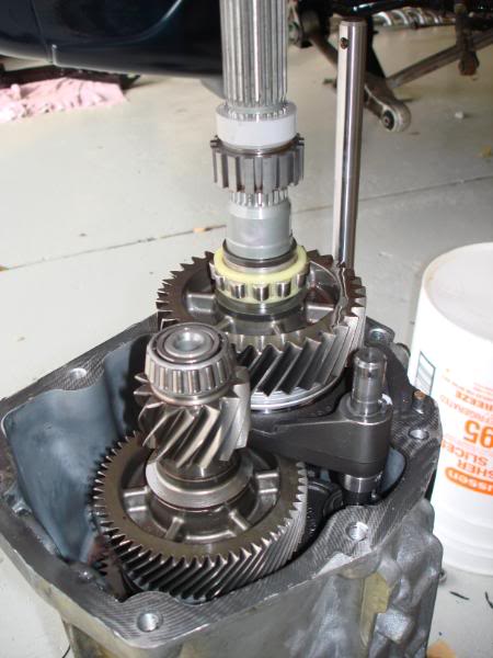
Inside the tailshaft housing.
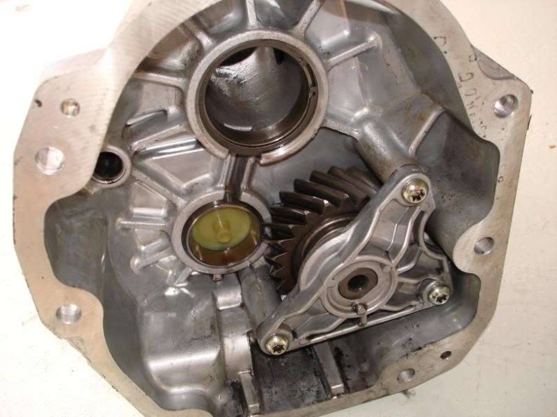
And now heres the kicker, the seam was not the source of the leakage, THE CRACK IN THE HOUSING is the source of the leak. Aparently some ape got ahold of a wrench and started crankin down on the drain plug and cracked the case.
I'm not sure what I'm going to do about this. I'm going to call Cleveland Pick A Part tomorrow and see what they say. From the film on the underside of the trans, this is clearly an issue that has been long term. I know I'm past my warrenty, but I'll see what they say, since I have proof that the trans has been sitting unused since the time I bought it.
I could replace the rear case, but then I'd have to reshim the bearings, and I don't know that I have the tools required for that.
I could weld hte case, but chances are the threads would melt away on since the material is so thin right there.
I could bore the hole out, and then drop in a smaller pipe half coulping, then weld around the top of that to seal it to the case.
I'm not sure where to go from here, but I'm at least going to talk to Cleveland Pick A Part first.
I think I came up with a solution. The tapped hole that cracked is approximately 0.710" diamter. It believe its 1/2" NPT. Since the transmission uses Dextron III fluid, which is really thin, I think I can get by with a smaller drain. A 1/4" NPT half coupling has a 0.75" OD. With a slight bit of grinding on the original threads, the 1/4" NPT bung will drop down inside. I can just weld the perimeter of the bung. Grind the crack down some, then weld the seam there. I think that a 1/4" NPT hole will be fine to drain the ATF.
Depending on sizing, I may do the same thing I just described buy with a 3/8" NPT bung as well. I just ordered both sizes and I'll see what works best.
I ground out the crack with a carbide grinder. The crack was completely through the part as I suspected. If you look closely in this picture, you can see the hairline crack. I grinded it out so i could weld the crack with 100% penetration. This way the material would be repaired in the stress path, not just welding over top of the crack and changine the stress path.
Then I slightly ground out the first few threads so that my new 1/4" NPT bung woudl fit in flush. Here is the item all mocked up.
Then I thought it would be a good idea to clean the case with brake parts cleaner. So I used about an entire can of cleaner on the case, which was sitting on my work bench. Here is where the huge mental brain fart occured. No less than 5 seconds after I got done dousing the part in brake parts cleaner, I thougth it would be a good idea to heat the crack, to burn out any left over trans fluid that may have been stuck in the crack. So I get my MAP GAS torch and touch the flame to the case. BOOOM, my entire work bench is on fire, good and tall flames, probalby 2 feet tall. So I jump back, realizing how stupid I had been. I decided to risk my arm hair and quickly push my trans case out of the fire. That didn't work, it just spread the fire even more. I grabbed the fire extingusiher, and contmeplated if i should use it for about 2 seconds. Then.....another brain fart occured, I tired to blow the fire out by.....blowing on it. Hahaha, blowing on a raging fire. Quickly realizing that it wasn't working, I decided the fire extinguisher was necessary and gave it a good spray. Put the fire right out with the quickness. My bench and wall are both all black from the flames about to catch them on fire. My trans case was all covered in black soot, right after I cleaned it. LOL. Well I'm retareded, what can I say.
After that fiasco, and some cleanup, I was ready to weld the trans drain plug. It turned out pretty nice I think. Then I thought I clean the weld off a bit before I took pictures, so I grab my trusty can of brake parts cleaner that already proved to be dangerous. Another moment of stupidity occured. I was not wearing my safety glasses like I almost always have on, and bam, the entire stream of brake parts cleaner went right into my eye.
**** that burns, then 15 minutes of rinsing it out with runnin water. That ****** can of brake parts cleaner is possessed!

The GTO shifter plate that moves the shifter input rearward.
Then I removed this piece, can't recall the name of it right now.
Then cracked the case loose.
Then pulled the case and here are some pics of the insides of the trans.
Inside the tailshaft housing.
And now heres the kicker, the seam was not the source of the leakage, THE CRACK IN THE HOUSING is the source of the leak. Aparently some ape got ahold of a wrench and started crankin down on the drain plug and cracked the case.
I'm not sure what I'm going to do about this. I'm going to call Cleveland Pick A Part tomorrow and see what they say. From the film on the underside of the trans, this is clearly an issue that has been long term. I know I'm past my warrenty, but I'll see what they say, since I have proof that the trans has been sitting unused since the time I bought it.
I could replace the rear case, but then I'd have to reshim the bearings, and I don't know that I have the tools required for that.
I could weld hte case, but chances are the threads would melt away on since the material is so thin right there.
I could bore the hole out, and then drop in a smaller pipe half coulping, then weld around the top of that to seal it to the case.
I'm not sure where to go from here, but I'm at least going to talk to Cleveland Pick A Part first.
I think I came up with a solution. The tapped hole that cracked is approximately 0.710" diamter. It believe its 1/2" NPT. Since the transmission uses Dextron III fluid, which is really thin, I think I can get by with a smaller drain. A 1/4" NPT half coupling has a 0.75" OD. With a slight bit of grinding on the original threads, the 1/4" NPT bung will drop down inside. I can just weld the perimeter of the bung. Grind the crack down some, then weld the seam there. I think that a 1/4" NPT hole will be fine to drain the ATF.
Depending on sizing, I may do the same thing I just described buy with a 3/8" NPT bung as well. I just ordered both sizes and I'll see what works best.
I ground out the crack with a carbide grinder. The crack was completely through the part as I suspected. If you look closely in this picture, you can see the hairline crack. I grinded it out so i could weld the crack with 100% penetration. This way the material would be repaired in the stress path, not just welding over top of the crack and changine the stress path.
Then I slightly ground out the first few threads so that my new 1/4" NPT bung woudl fit in flush. Here is the item all mocked up.
Then I thought it would be a good idea to clean the case with brake parts cleaner. So I used about an entire can of cleaner on the case, which was sitting on my work bench. Here is where the huge mental brain fart occured. No less than 5 seconds after I got done dousing the part in brake parts cleaner, I thougth it would be a good idea to heat the crack, to burn out any left over trans fluid that may have been stuck in the crack. So I get my MAP GAS torch and touch the flame to the case. BOOOM, my entire work bench is on fire, good and tall flames, probalby 2 feet tall. So I jump back, realizing how stupid I had been. I decided to risk my arm hair and quickly push my trans case out of the fire. That didn't work, it just spread the fire even more. I grabbed the fire extingusiher, and contmeplated if i should use it for about 2 seconds. Then.....another brain fart occured, I tired to blow the fire out by.....blowing on it. Hahaha, blowing on a raging fire. Quickly realizing that it wasn't working, I decided the fire extinguisher was necessary and gave it a good spray. Put the fire right out with the quickness. My bench and wall are both all black from the flames about to catch them on fire. My trans case was all covered in black soot, right after I cleaned it. LOL. Well I'm retareded, what can I say.
After that fiasco, and some cleanup, I was ready to weld the trans drain plug. It turned out pretty nice I think. Then I thought I clean the weld off a bit before I took pictures, so I grab my trusty can of brake parts cleaner that already proved to be dangerous. Another moment of stupidity occured. I was not wearing my safety glasses like I almost always have on, and bam, the entire stream of brake parts cleaner went right into my eye.
**** that burns, then 15 minutes of rinsing it out with runnin water. That ****** can of brake parts cleaner is possessed!
05-20-10, 09:14 AM
#19
Theres how it turned out.
Then I began to modify the little part above the oil filter for my oil pressure gauge. Its not welded yet, but this is what it will look like. It should tuck the sensor up against the motor pretty tight.
What......Kevin used JB Weld. The world is going to end soon. Hahah
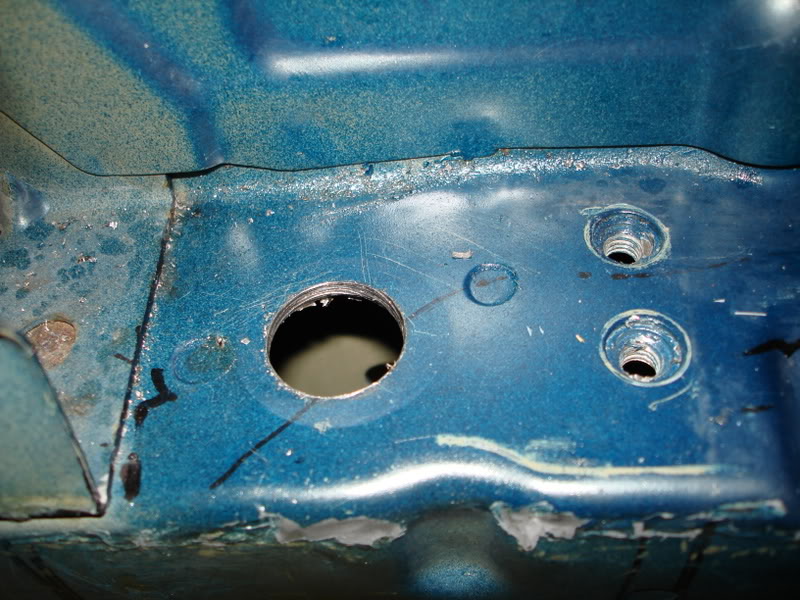
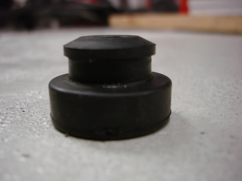
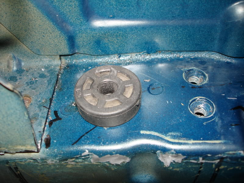
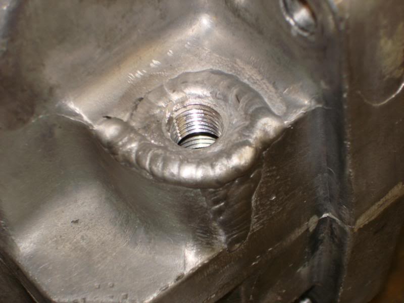
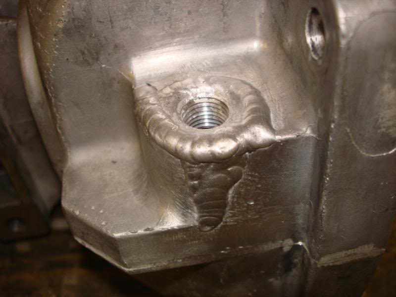
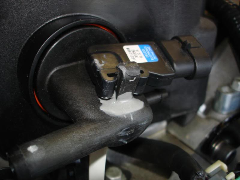
I broke off the hold-down for the MAP sensor, so I JB Welded it back on.
Then....I used it again. I'm on a roll. I needed to seal up a hole in the firewall. The hole is from there the AC lines entered the passenger compartment. I just used a piece of aluminum to seal the hole up, and what a better way to attach it than JB Weld. Seems like it was a good idea, hope it proves itself to be true.
I made a jumper to bypass the clutch starter interlock switch. This will let me start the car w/o pressing the clutch in. The most bearing wear occurs during starts, and with a stiff clutch there would be a lot of pressure on the thrust bearing during starts. And having the engine sitting for so long w/o running I think the oil film will be next to none. I think this should help out on first start, and maybe I'll leave it like this long term, I havn't decided. This little guy plugs right into the clutch interlock plug.

Now you see it:
Now you don't:
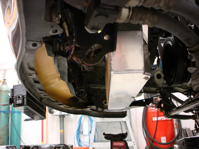
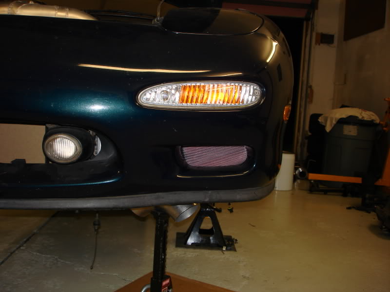
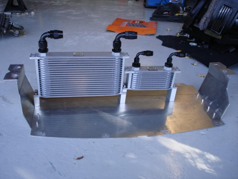
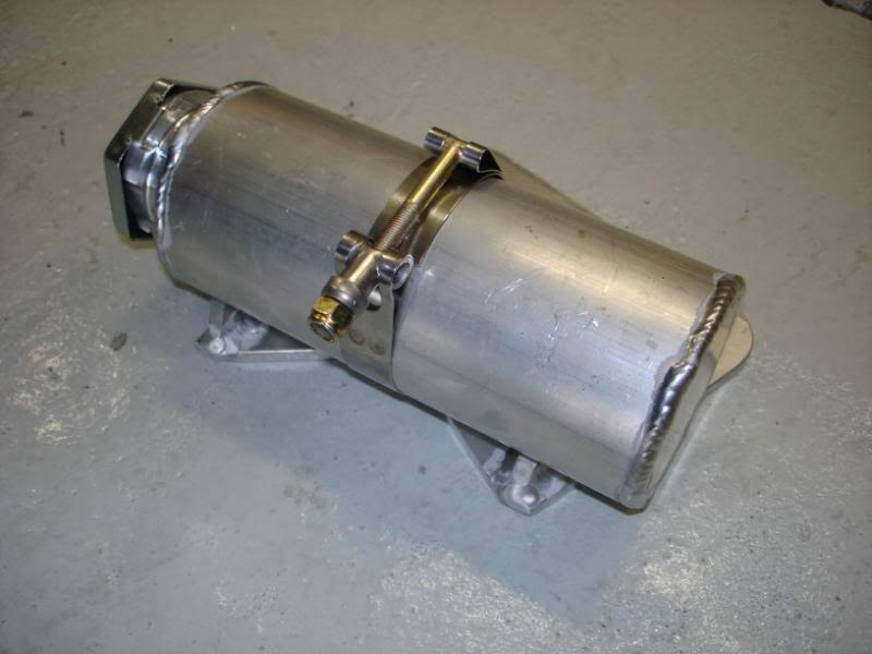
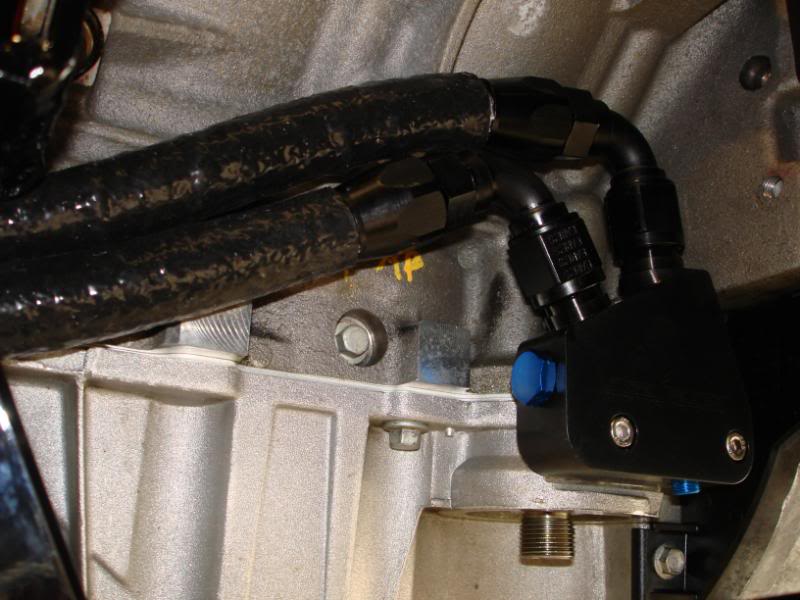
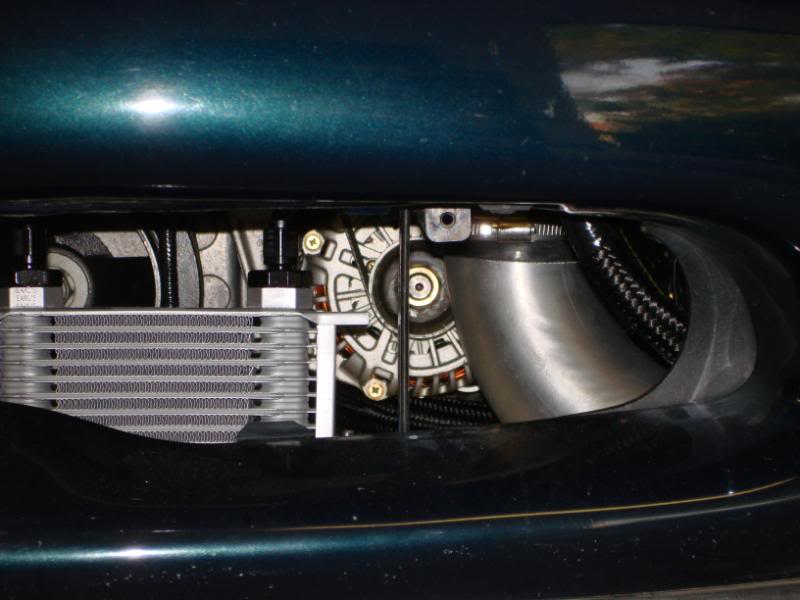
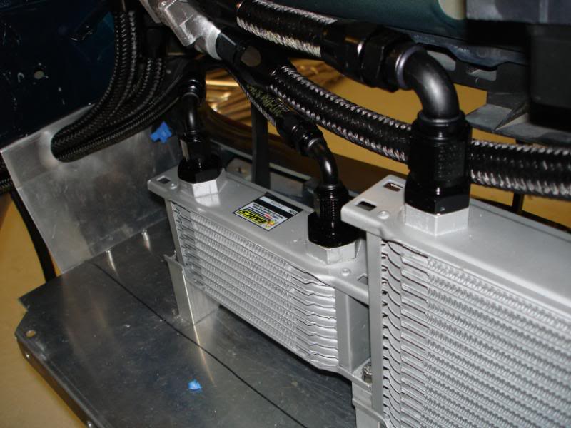
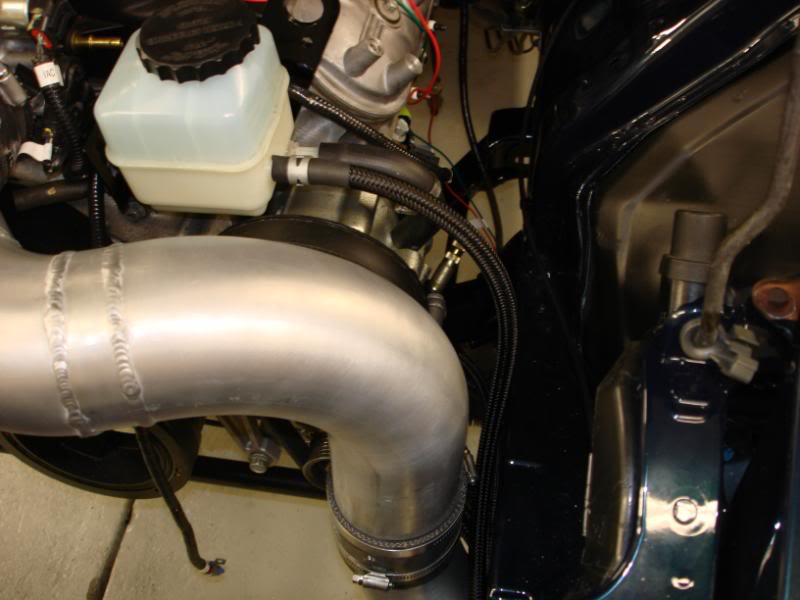
So yeah, I got working on my cooler installation. I've got the oil and power steering cooler mounted. I am using Earls coolers and earls prolite 350 hose and anotuff fittings. -10 lines for the oil cooler, -6 lines for the power steering cooler. I am using a Mocal high-temp oil cooler, fully open at 200 deg F. I also removed the foglights for improved airflow, and I didn't really like the way they looked anyways.
Coolers mounted to my lower radiator plate. I used aluminum tubing as spacers to get the coolers into the airflow, otherwise the lower bumper cover obstructed the airflow to them.
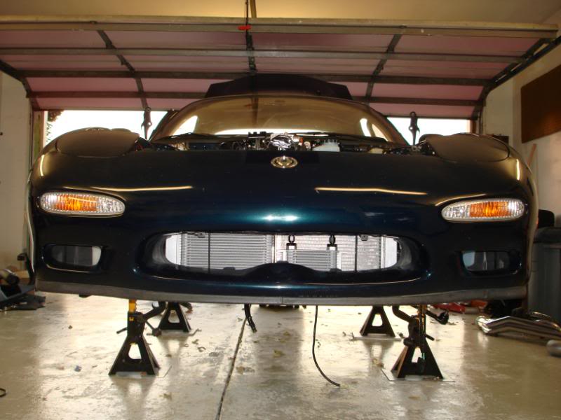
Installed in the car with the radiator.
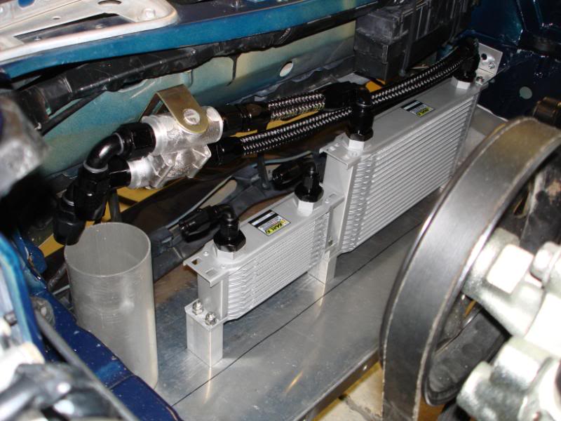
Oil thermostat and lines ran from that to the oil cooler.
Then I began to modify the little part above the oil filter for my oil pressure gauge. Its not welded yet, but this is what it will look like. It should tuck the sensor up against the motor pretty tight.
What......Kevin used JB Weld. The world is going to end soon. Hahah
I broke off the hold-down for the MAP sensor, so I JB Welded it back on.
Then....I used it again. I'm on a roll. I needed to seal up a hole in the firewall. The hole is from there the AC lines entered the passenger compartment. I just used a piece of aluminum to seal the hole up, and what a better way to attach it than JB Weld. Seems like it was a good idea, hope it proves itself to be true.
I made a jumper to bypass the clutch starter interlock switch. This will let me start the car w/o pressing the clutch in. The most bearing wear occurs during starts, and with a stiff clutch there would be a lot of pressure on the thrust bearing during starts. And having the engine sitting for so long w/o running I think the oil film will be next to none. I think this should help out on first start, and maybe I'll leave it like this long term, I havn't decided. This little guy plugs right into the clutch interlock plug.
Now you see it:
Now you don't:
So yeah, I got working on my cooler installation. I've got the oil and power steering cooler mounted. I am using Earls coolers and earls prolite 350 hose and anotuff fittings. -10 lines for the oil cooler, -6 lines for the power steering cooler. I am using a Mocal high-temp oil cooler, fully open at 200 deg F. I also removed the foglights for improved airflow, and I didn't really like the way they looked anyways.
Coolers mounted to my lower radiator plate. I used aluminum tubing as spacers to get the coolers into the airflow, otherwise the lower bumper cover obstructed the airflow to them.
Installed in the car with the radiator.
Oil thermostat and lines ran from that to the oil cooler.
05-20-10, 09:15 AM
#20
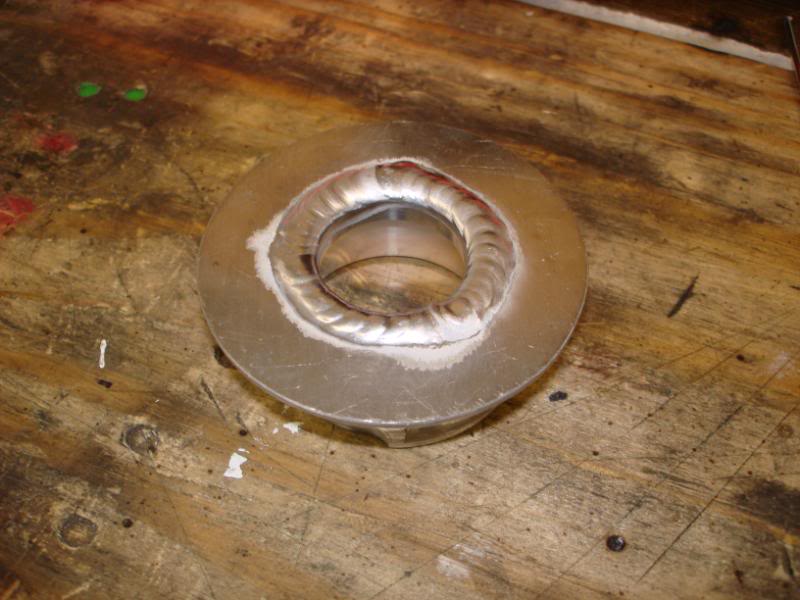
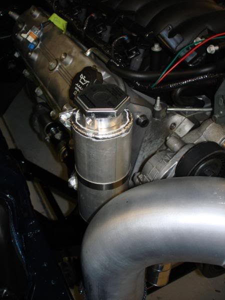
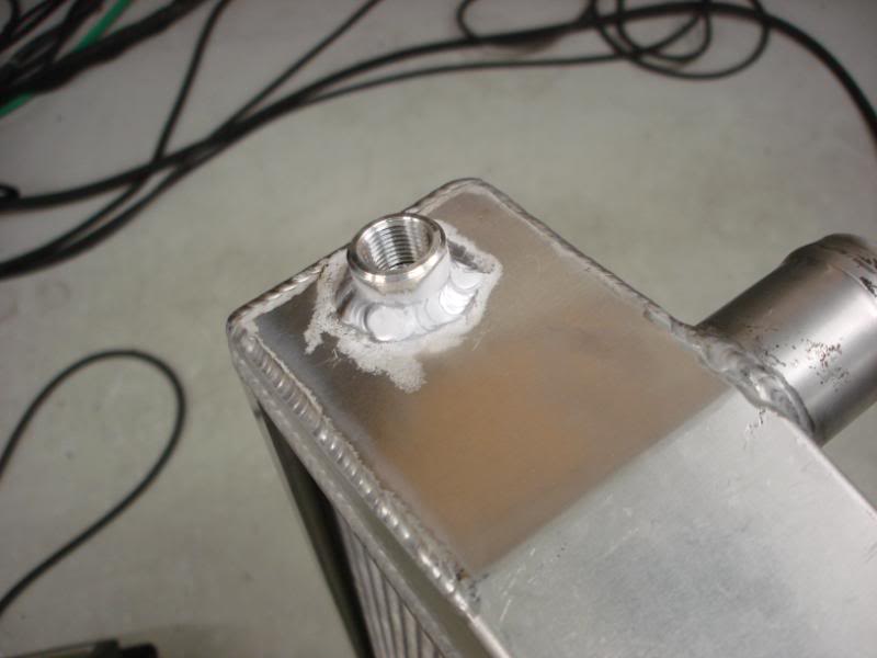
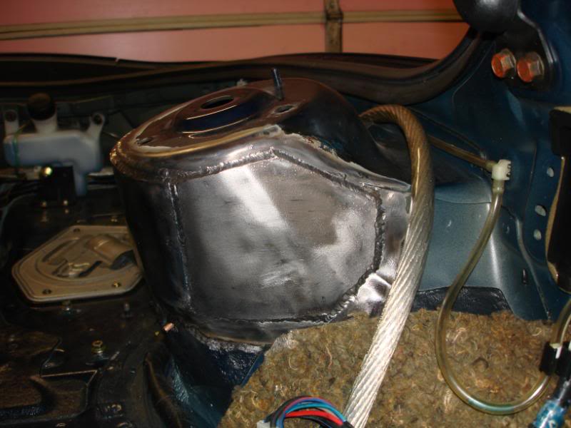
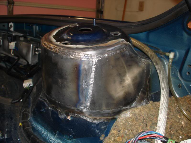
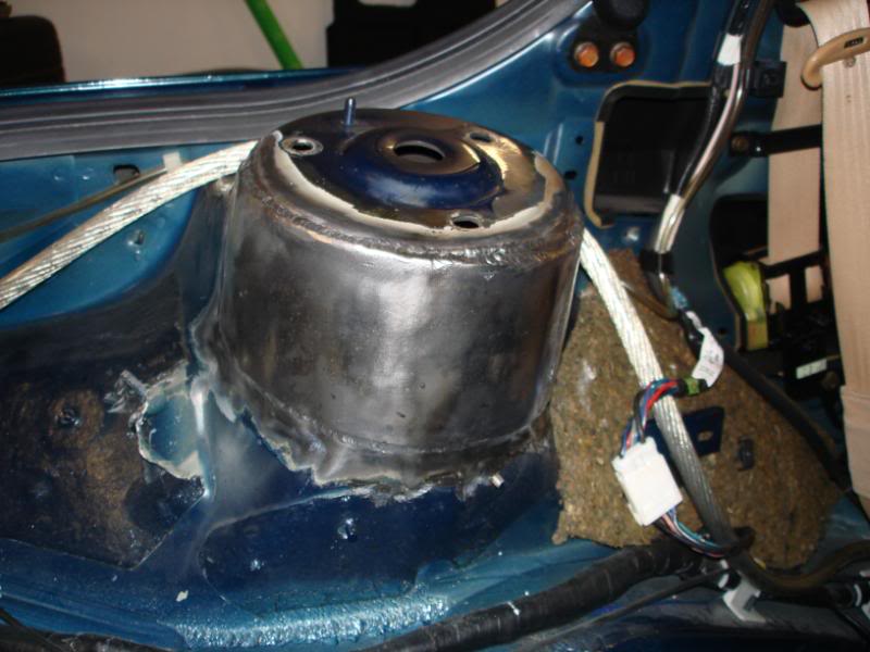
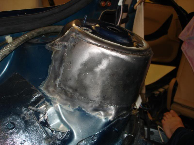
I made my coolant surge tank today. I made it from 0.065" wall 3" tubing. Then I also made a bracket to hold it to the passenger side head. I have probalby 3" above the steam vent. I still have to weld on some half couplings before its complete. I'm very happy with how this turned out. Only about 8 hours of work in it.
The radiator cap piece welded from the inside.
Endcaps welded on.
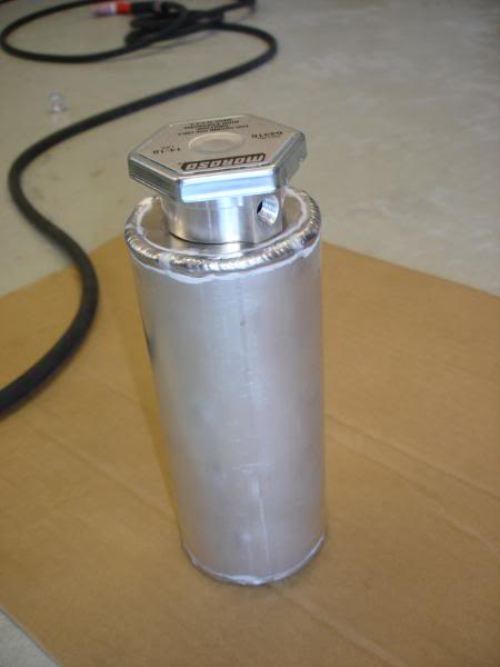
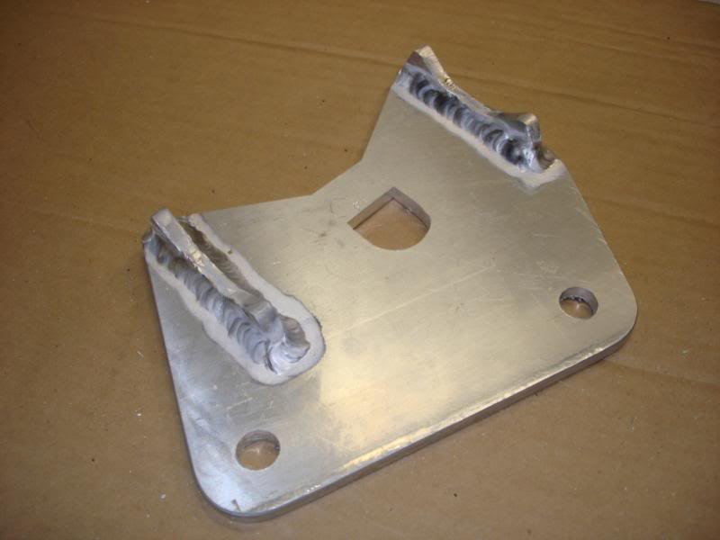
Bracket to hold it to the head. Its made from 1/4" 6061 T6 aluminum.
On the bracket.
On the engine.
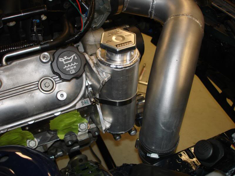
I'm definately gettin close. But I can't really say how close I am.
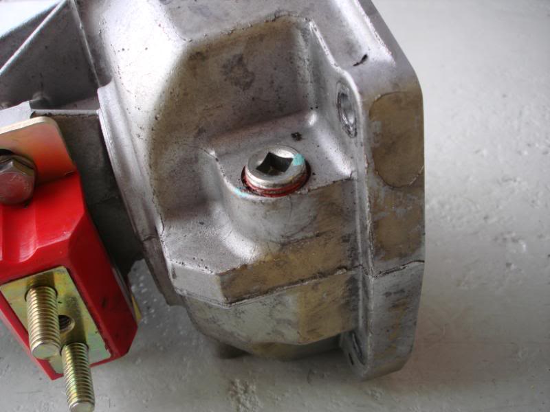
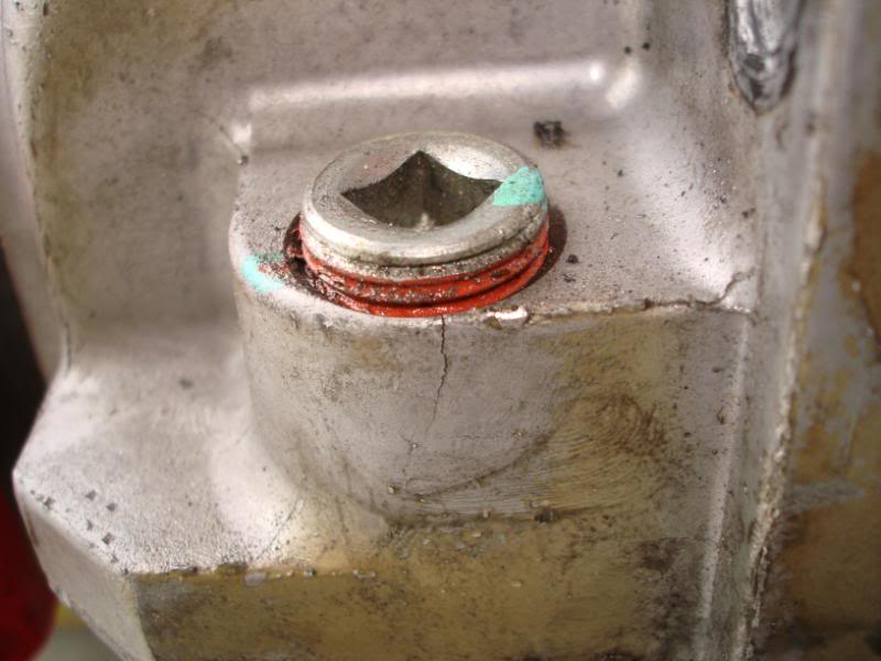
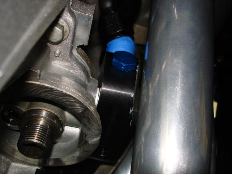
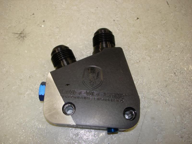
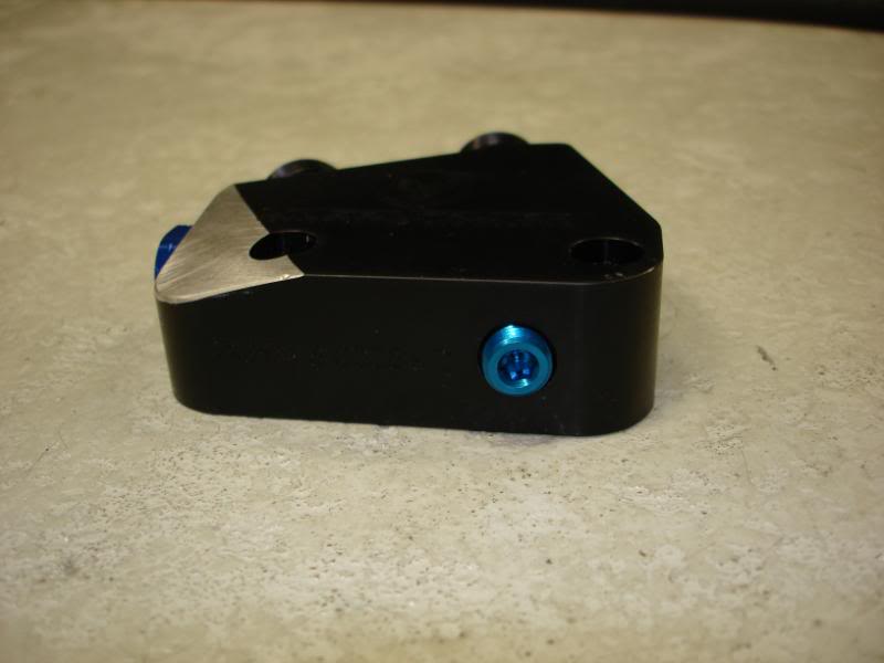
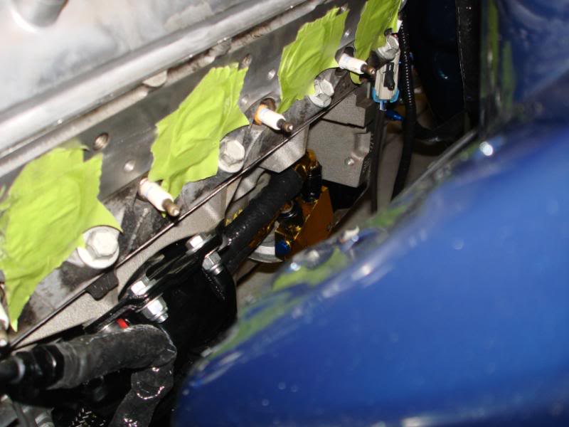
I got my oil cooler install all finished up. I ran -10 lines, a mocal oil t-stat, and earls cooler. I put some DEI fire sleve over the lines where they go into the adapter block. Its good to 500 degrees constant, and 2000 intermittant. I used a Lingenfelter oil cooler adapter block. I had to grind the corner of the block down for clearance for the header. There was probalby 1/32" of clearance before I ground it down. I will be putting that gold heat reflective stuff on the block, and around the 90 degree fittings to help protect those. The headers are also ceramic coated inside and out, so it might be overkill as usual.
 05-20-10, 09:17 AM
#21
And Roxy, she won't leave me alone when I'm under my car working. Too cute.

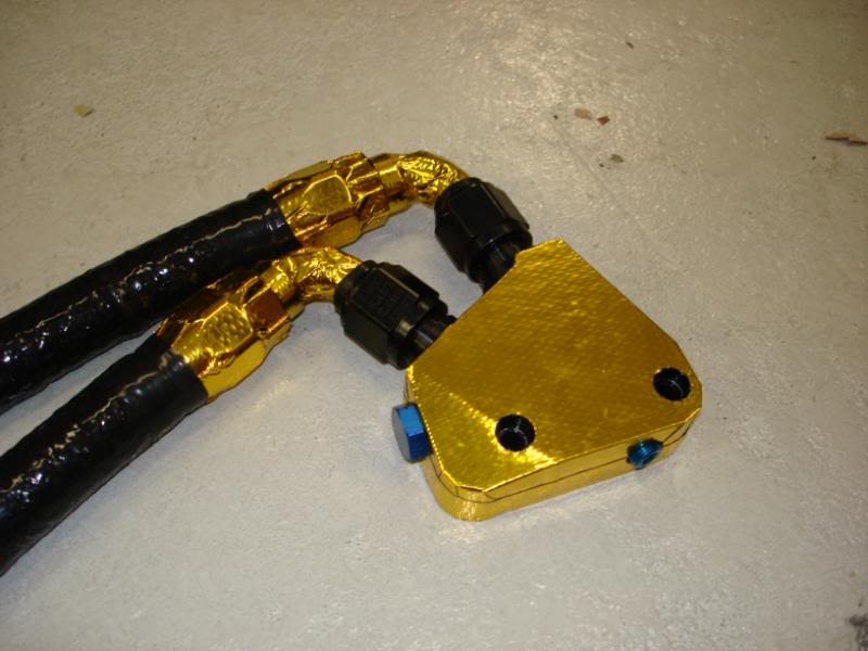
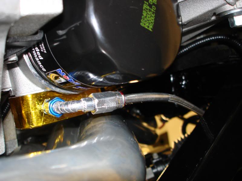
Gotta have some gold in the car just so I can say its worth millions. I remade my oil cooler adapter out of solid gold. I also made the hose ends out of solid gold as well.
Errrr. I put some of that super badass racecar gold reflective film on those pieces. The hose itself has that silicone coverd fiberblass sheath. I think that should successfully block enough heat.
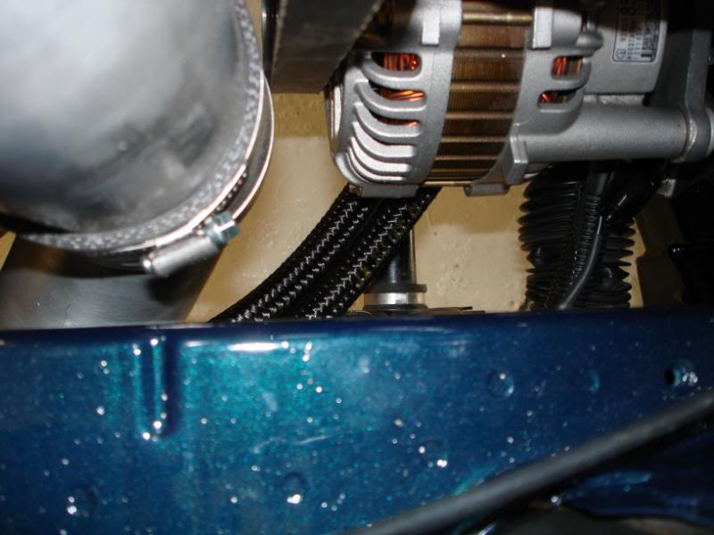
I also finished my power steerin cooler install.
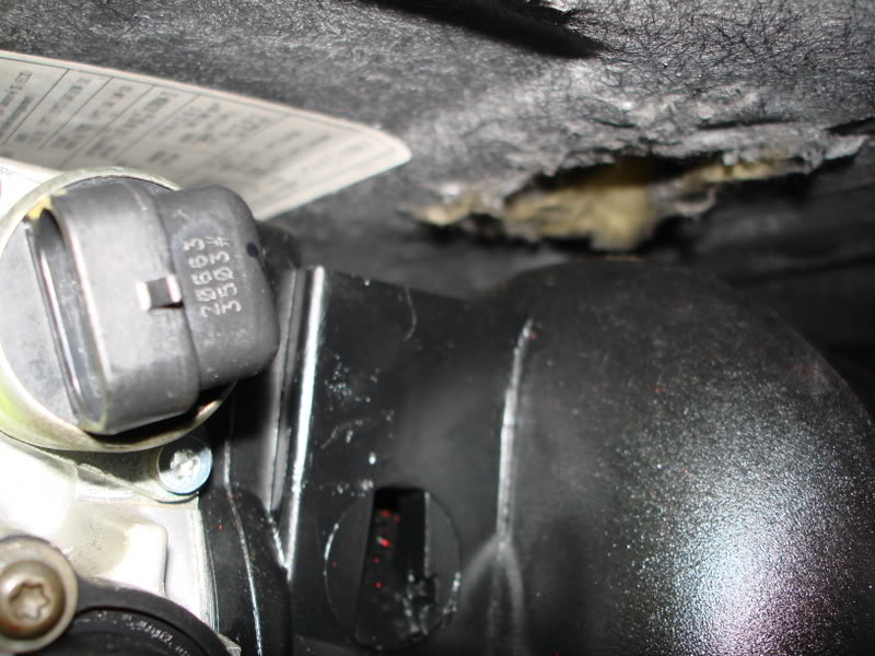
I got a new IAT sensor that threads into an NPT bung, unlike the stock one which pushes into a grommet. I had to do a comparison of the calibration curves to make sure they're the same. Here is what I found.
[img width=775 height=465]http://i93.photobucket.com/albums/l55/Kevin_Doe/RX-7/IATCalibration.jpg[/img]
Welded some aluminum bungs in my radiator and my coolant surge tank.
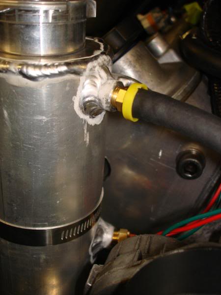
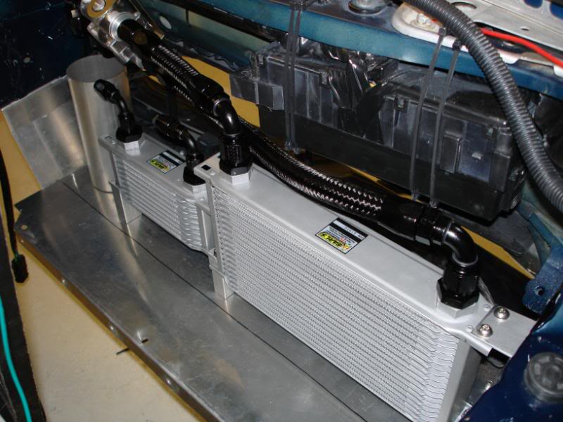
I finished running and connecting the cooler lines. I also protected the hoses from the raw edge of the aluminum plate. I used that door edge stripping.
 05-20-10, 09:17 AM
#22
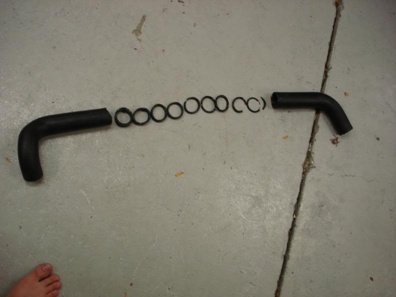
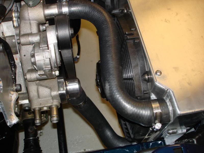
Then I went to the radiator hose store (Autozone) and picked out some hoses that I thougth work work well. Then brought out the razor blade trying to make the fitment perfect. Always take a little at a time. You can alway cut more, but can't add it back on.
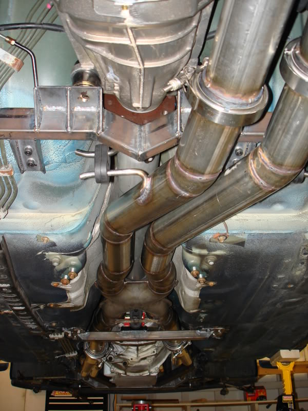
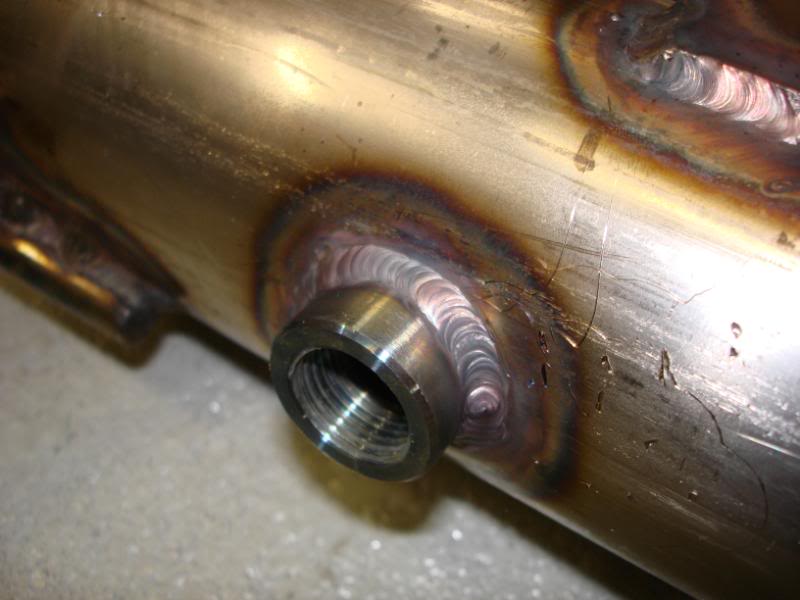
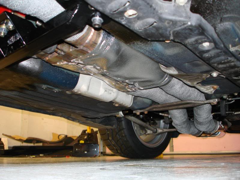
Then I welded a bung into my exhuast for my Innovate LC-1 wideband.
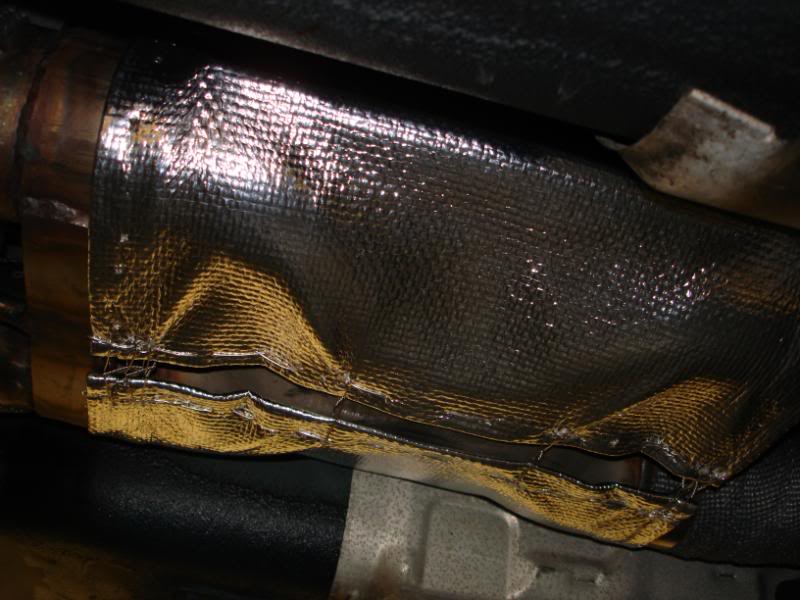
Then I welded wrapped my exhaust. I did it to keep my driveshaft cool, and to keep the tunnel cool as well.
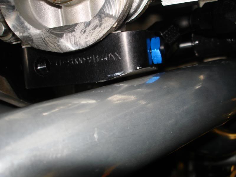
I installed the oil cooler adapter block.
Then I made up a small flex line for the oil pressure sensor. It runs VERY close to the header, so I put a condom on it (protection).
And installed
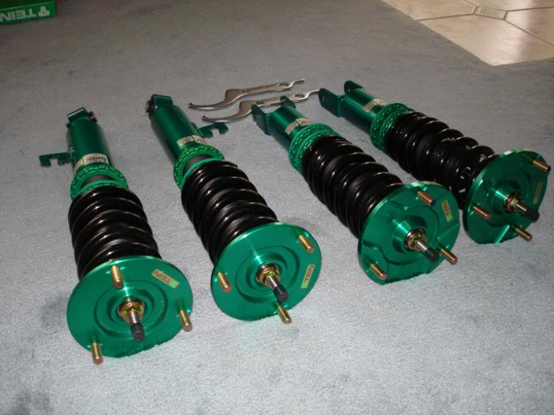
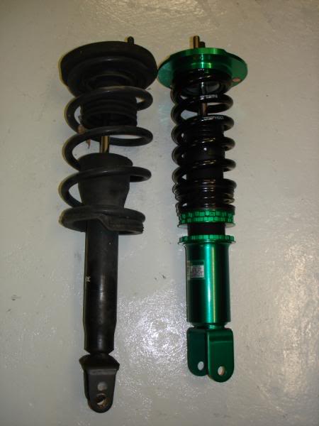
Then my shipment from Tein showed up. They offered me a partial sponsorship, and I accepted their terms. I ended up getting the brand new Tein Mono Flex. Its similar to the Flex, but its a monotube. Its made to bridge the gap that was between the Flex and the Super race. They're single adjustable, ride height/corner weight adjustable w/o changing static spring preload, etc, etc. They have 14kg/mm front springs, and 12kg/mm rears with helpers in the rear. They look to be of VERY good quality. So far I have the rears installed, and I'll be putting the fronts on tomorrow.
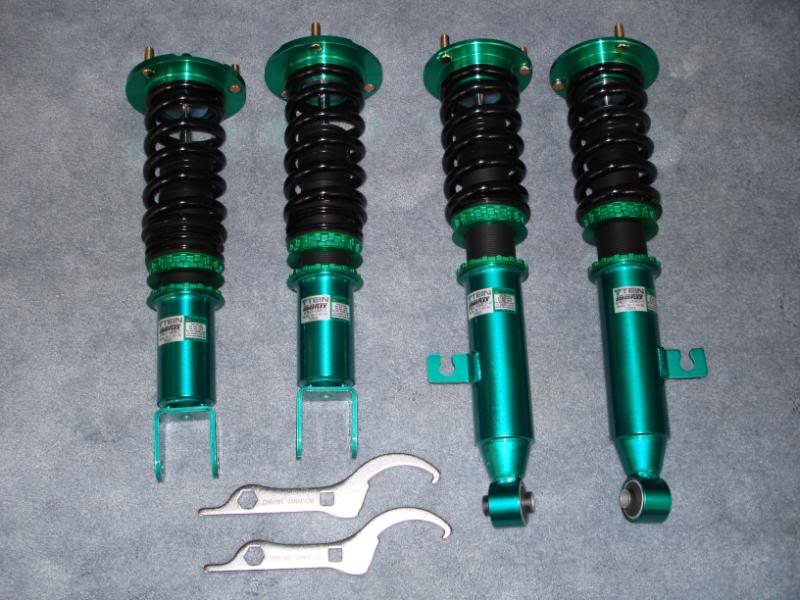
rear comparison
I've been working on getting my car to a runnig state. I have been struggling with EFI Live. I"m very much a DIY kinda guy, so I'm trying to learn all the EFI Live stuff and I've been struggling. I can tune well, but only if the car is drivable enough to log data. So far the car isn't drivable with the current tune. I think I made a mistake on one of the parmaters in the tune, putting me into a ultra backup mode where the PCM doesn't use MAP or MAF, basically a completely fucked up tune that runs at like 20:1 AFR and accepts absolutely no throttle. Some guys on EFI LIve forums took a look at my tune and notified me of the issue. I'm going to give it a try tomorrow, and if it works, I'll be gettin an alighment and corner weighted friday night.
2MCHPWR, care to share your alighment specs? Do you run differnet specs for autox and TT? I'm so new to FDs, I don't really know what they like on the courses. You seem very experienced, so I'd like your input.
Then I welded a bung into my exhuast for my Innovate LC-1 wideband.
Then I welded wrapped my exhaust. I did it to keep my driveshaft cool, and to keep the tunnel cool as well.
I installed the oil cooler adapter block.
Then I made up a small flex line for the oil pressure sensor. It runs VERY close to the header, so I put a condom on it (protection).
And installed
Then my shipment from Tein showed up. They offered me a partial sponsorship, and I accepted their terms. I ended up getting the brand new Tein Mono Flex. Its similar to the Flex, but its a monotube. Its made to bridge the gap that was between the Flex and the Super race. They're single adjustable, ride height/corner weight adjustable w/o changing static spring preload, etc, etc. They have 14kg/mm front springs, and 12kg/mm rears with helpers in the rear. They look to be of VERY good quality. So far I have the rears installed, and I'll be putting the fronts on tomorrow.
rear comparison
I've been working on getting my car to a runnig state. I have been struggling with EFI Live. I"m very much a DIY kinda guy, so I'm trying to learn all the EFI Live stuff and I've been struggling. I can tune well, but only if the car is drivable enough to log data. So far the car isn't drivable with the current tune. I think I made a mistake on one of the parmaters in the tune, putting me into a ultra backup mode where the PCM doesn't use MAP or MAF, basically a completely fucked up tune that runs at like 20:1 AFR and accepts absolutely no throttle. Some guys on EFI LIve forums took a look at my tune and notified me of the issue. I'm going to give it a try tomorrow, and if it works, I'll be gettin an alighment and corner weighted friday night.
2MCHPWR, care to share your alighment specs? Do you run differnet specs for autox and TT? I'm so new to FDs, I don't really know what they like on the courses. You seem very experienced, so I'd like your input.
05-20-10, 09:18 AM
#23
A little bit of an update.
In closed loop mode, the car runs pretty good on stock tune. However you can't really map the VE table with this tune. And like I said above I have been struggling to properly get the car into open loop, speed density, but I think I know the solution. Hopefully so, tomorrow will tell all.
Running in closed loop speed density.
Then I decied to be Sussie Homemaker and do a little sewing, only it was man sewing. No thread and needle here, no cotton thread. Fiberglass cloth and stainless wire for thread. LOL. I wrapped my exhuast, but the X-pipe didn't seem like ti was going to wrap that well. My exhaust and x-pipe comes probably within 1.5" of my driveshaft, so I didn't want my aluminum driveshaft absorbin all that heat. The wrapped pipes took care of that, but I needed to do somethin with the X-pipe. I decided to make a little covering custom style. I bought a big sheet of DEI's heat blanket stuff.
I started cutting to shape, marking, and sewing the edges to make for a clean look.
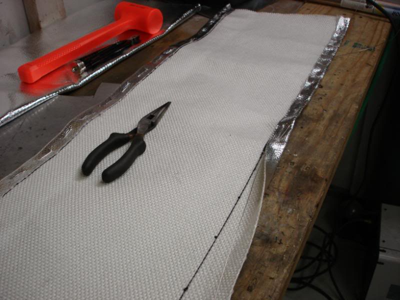
Then I measured for the lenth, and sewed the ends up. I was using 0.032 stainless safety wire to sew with. i reinforced the ends pretty good with the wire as well.
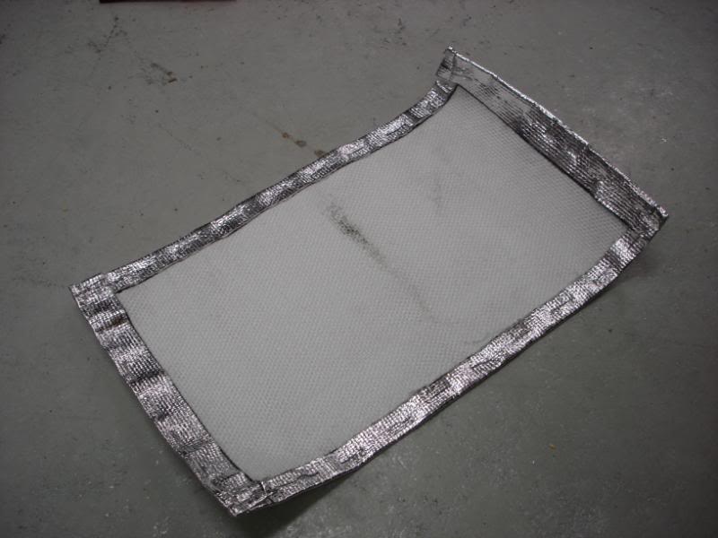
And wrapped around the X-pipe, and safety wired in place for a nice snug fit.
An axle failure kept me from making it to the cruise. I should be back up in runnning in probably a week.
A broken axle didn't stop me from cleaning the car up and taking some pics though.
I'm building a custom roll bar setup for my car. I didn't like any of the available kits, so I decided I'd build my own. I don't/won't race in any sanctioned event where the cage needs to meet any specs. I will run test and tune drag events, and autox, and mainly HPDE/TT events. None of those need a spec'd out cage. I designed it so that it will hopefully meet those requirements, but if not, I don't mind too much. I want the cage for two reasons. Safety, and rigidity, safety being the most important.
Here is my best attempt at describing the design. Its going to be a chromoly setup, tig welded. Rob at Rigid will be bending and notching the tubes for me.
1. Main hoop.
2. Harness bar.
3. Diagnal through the main hoop.
4. Door bars, rigid bars, no swingouts here.
5. From the main hoop where the door bars intersect, to the front of the shock towers.
6. From the top outsides of the main hoop to the front of the shock towers.
7. Shock tower bar that goes between the two towers.
8. From the top outsides of the main hoop to the insides of the shock tower, possibly onto the very outsides of the tower bar.
9. Possibly a bar from the main hoop floor mount, to the middle of the door bar.
The door bar will extend to the same location where my heel rests, but outside the clutch petal a few inches. The main hoop will attach to the stiffening brade that runs right under the front of the rear buckets. Not all these tubes will be 1 5/8" 0.083. They will be smaller where allowed to save weight.
So far all I have done is the rear shock tower plates. They're HRPO 10 gauge (1/8" basically) steel. First I started out with the virgin towers, then welded the seam at the top. Then banged out some pieces to wrap most of the way around the towers. I don't have any such tools to bend this thickness of metal, so I laid it in the dirt, and just started pounding away with a 2 lb hammer till it was taking the shape I wanted. I had to make it out of two seperate pieces so it was easier to work with. Then I TIG welded it all down after I wire wheeled the paint off.
In closed loop mode, the car runs pretty good on stock tune. However you can't really map the VE table with this tune. And like I said above I have been struggling to properly get the car into open loop, speed density, but I think I know the solution. Hopefully so, tomorrow will tell all.
Running in closed loop speed density.
Then I decied to be Sussie Homemaker and do a little sewing, only it was man sewing. No thread and needle here, no cotton thread. Fiberglass cloth and stainless wire for thread. LOL. I wrapped my exhuast, but the X-pipe didn't seem like ti was going to wrap that well. My exhaust and x-pipe comes probably within 1.5" of my driveshaft, so I didn't want my aluminum driveshaft absorbin all that heat. The wrapped pipes took care of that, but I needed to do somethin with the X-pipe. I decided to make a little covering custom style. I bought a big sheet of DEI's heat blanket stuff.
I started cutting to shape, marking, and sewing the edges to make for a clean look.
Then I measured for the lenth, and sewed the ends up. I was using 0.032 stainless safety wire to sew with. i reinforced the ends pretty good with the wire as well.
And wrapped around the X-pipe, and safety wired in place for a nice snug fit.
An axle failure kept me from making it to the cruise. I should be back up in runnning in probably a week.
A broken axle didn't stop me from cleaning the car up and taking some pics though.
I'm building a custom roll bar setup for my car. I didn't like any of the available kits, so I decided I'd build my own. I don't/won't race in any sanctioned event where the cage needs to meet any specs. I will run test and tune drag events, and autox, and mainly HPDE/TT events. None of those need a spec'd out cage. I designed it so that it will hopefully meet those requirements, but if not, I don't mind too much. I want the cage for two reasons. Safety, and rigidity, safety being the most important.
Here is my best attempt at describing the design. Its going to be a chromoly setup, tig welded. Rob at Rigid will be bending and notching the tubes for me.
1. Main hoop.
2. Harness bar.
3. Diagnal through the main hoop.
4. Door bars, rigid bars, no swingouts here.
5. From the main hoop where the door bars intersect, to the front of the shock towers.
6. From the top outsides of the main hoop to the front of the shock towers.
7. Shock tower bar that goes between the two towers.
8. From the top outsides of the main hoop to the insides of the shock tower, possibly onto the very outsides of the tower bar.
9. Possibly a bar from the main hoop floor mount, to the middle of the door bar.
The door bar will extend to the same location where my heel rests, but outside the clutch petal a few inches. The main hoop will attach to the stiffening brade that runs right under the front of the rear buckets. Not all these tubes will be 1 5/8" 0.083. They will be smaller where allowed to save weight.
So far all I have done is the rear shock tower plates. They're HRPO 10 gauge (1/8" basically) steel. First I started out with the virgin towers, then welded the seam at the top. Then banged out some pieces to wrap most of the way around the towers. I don't have any such tools to bend this thickness of metal, so I laid it in the dirt, and just started pounding away with a 2 lb hammer till it was taking the shape I wanted. I had to make it out of two seperate pieces so it was easier to work with. Then I TIG welded it all down after I wire wheeled the paint off.
05-20-10, 09:19 AM
#24
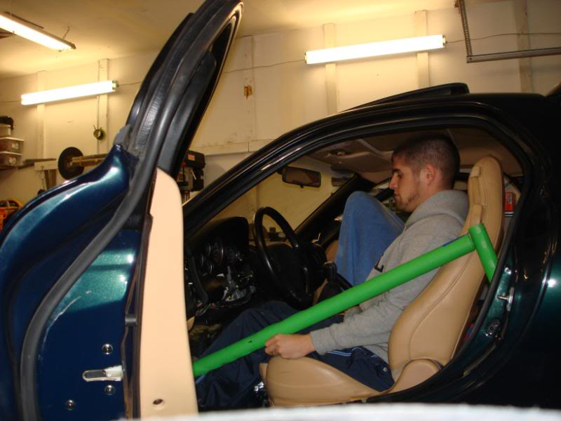
During the mockup stages of the design. I was doing this since the clearance between the seat and door pannel was so tight. I also wanted to make sure I could get in and out of the car with the bar where it was. With a friend holding the tube, I was able to get out with a bit of dexterity, hopefully its gets easier with repetition. The steering wheel really makes it tough with the way the seat is so low. The tube crosses my arm right betwene my shoulder and elbow as it should. Ignore the other green tube, that is just there to hold the door bar up, that is not how the main hoop will be.
Cut out the main hoop plates and welded the driver side plates down. All TIG welded.
Then I made a tape cage (coolnicks idea), to help me visualize my plans. I'm very glad I did that. I relaized that I had gone overboard on the planning. I after seeing this I decided to remove the rear X. I think that should clear up a lot of clutter, and the shouldn't really affect the function too much.
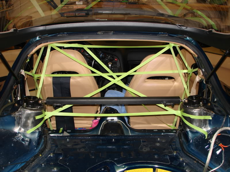
Finished up the last of the floor plates tonight. I did the plates where the door bars will hit the floor up in the footwells. Since I didn't weld onto two or more planes, I made sure the plates I used would distrubute the load over as large of an area as possible, so I used two 1/8" plates, and made the top plate smaller than the bottom plate. I TIG welded the two plates together, and MIG welded the plates to the floor. So far this was the only MIG welding I've done on the plates, and will be the only MIG welds on the whole cage. I didn't feel like removing parts of hte dash, and pedals to get the TIG torch in there, and dind't feel like being contorted like a circus freak trying to get my body up in that tiny *** spot and TIG weld. After I got done MIG welding them in, I was reminded why I hate MIG welding. It looks like ****, and splatter, I hate that. Oh well, it should be plenty strong, and serve its purpose quite well.
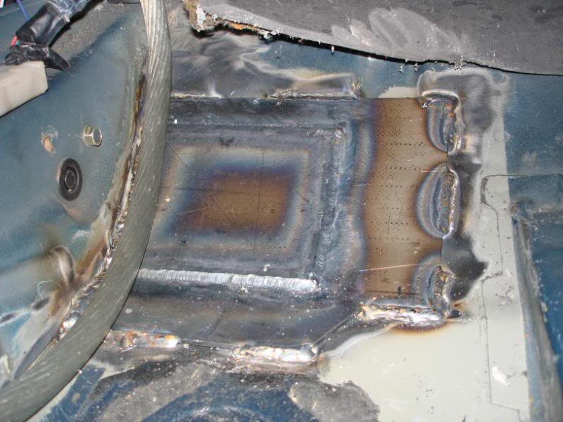
I've made some good progress on the roll bar. I originally talked to Rob at Rigid Race Cars about the car. We agreed that I would do everything besides bending and notching the tubes. Basically I took my car to him with the interior all stripped, and the floor plates welded in. He was going to just bend and notch all the tubes, then I was giong to take it home and do the welding myself. Once I got there, and things started progressing well, I decided to have him do the welding as well. I was there with him most days helping as much as I could w/o getting in his way.
I had the design of the cage 90% complete, and Rob had some nice suggestions for small changes. We planned it out pretty well, then got to work. I want to really thank the crew at Rigid Race Cars (Rob and Justin) for doing a fantastic job. I am extremely impressed with how it turned out. Rob really has some great ideas and is a great fabricator. I'm a hard guy to impress as far as quality designed and fabricated stuff goes, and Rigid has definately impressed me. I would recommend Rigid Race Cars to anyone who needs custom fabrication done, they won't do you wrong.
Now for the good stuff. The first pic is during mockup, and the rest of the pics are of the roll bar finsihed. The next steps are welding on some tabs for various things, then painting it with Por-15. Then a little more interior trimming, and putting the whole interior back in.
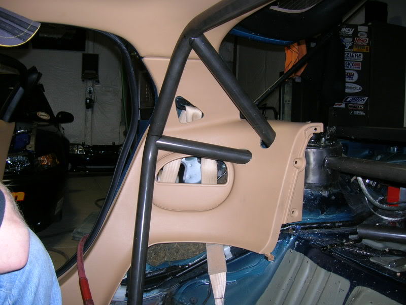
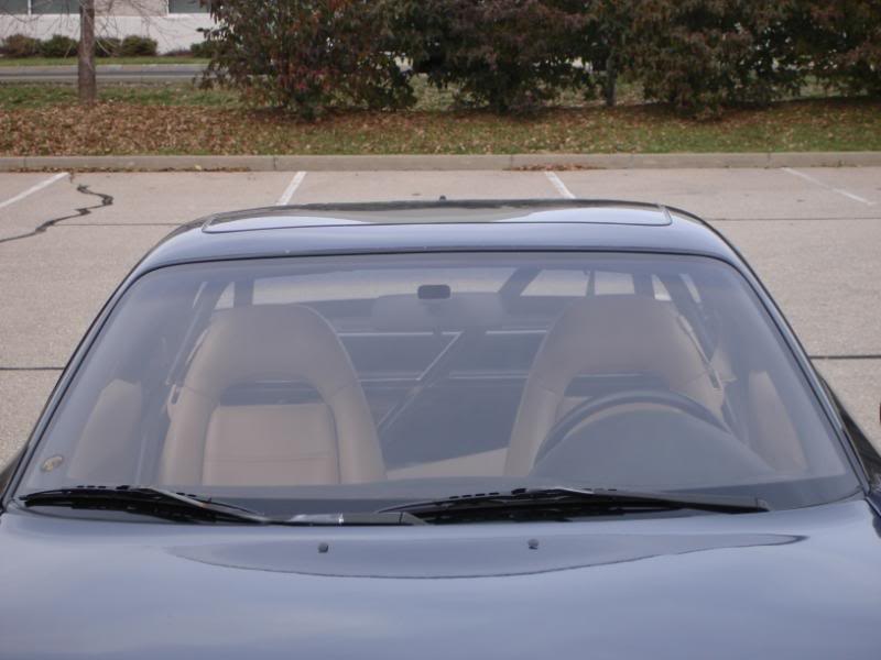
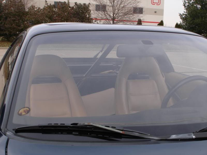
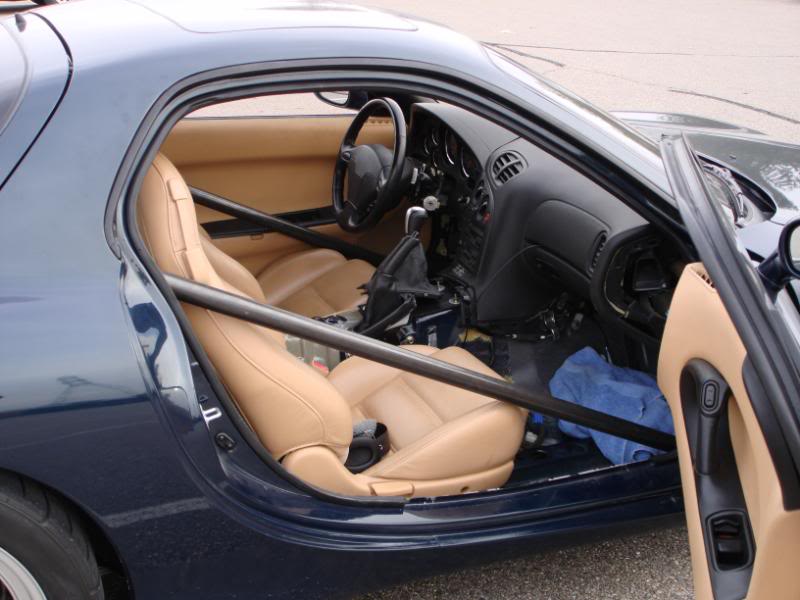
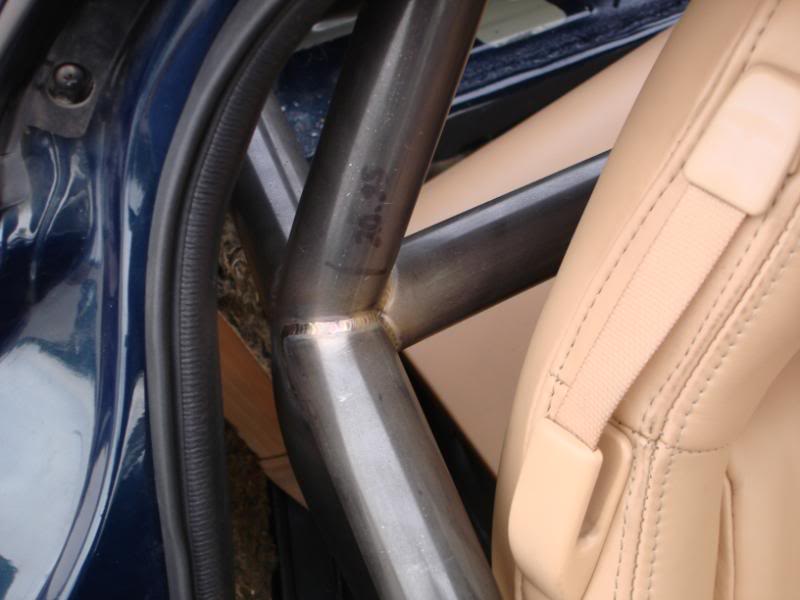
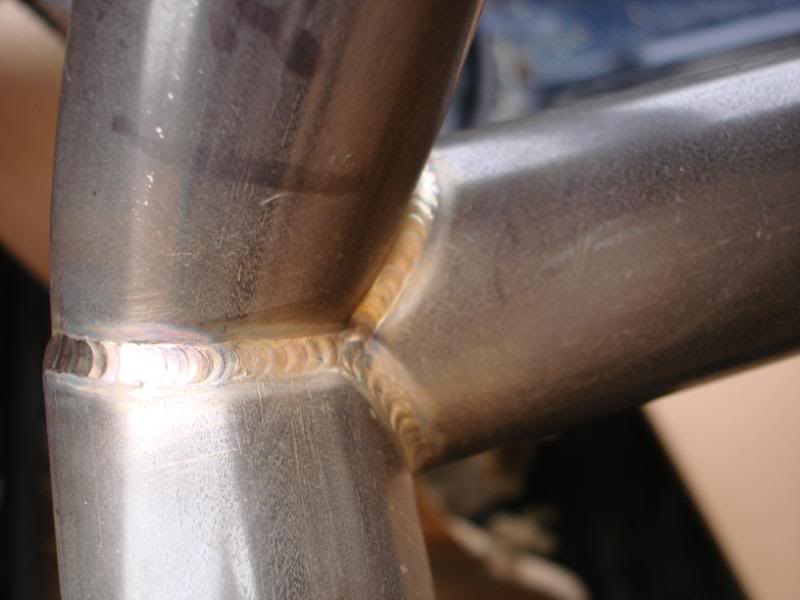
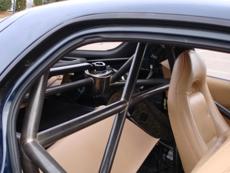
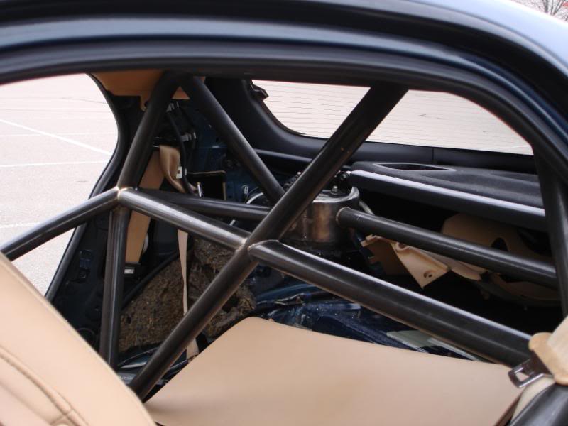
Cut out the main hoop plates and welded the driver side plates down. All TIG welded.
Then I made a tape cage (coolnicks idea), to help me visualize my plans. I'm very glad I did that. I relaized that I had gone overboard on the planning. I after seeing this I decided to remove the rear X. I think that should clear up a lot of clutter, and the shouldn't really affect the function too much.
Finished up the last of the floor plates tonight. I did the plates where the door bars will hit the floor up in the footwells. Since I didn't weld onto two or more planes, I made sure the plates I used would distrubute the load over as large of an area as possible, so I used two 1/8" plates, and made the top plate smaller than the bottom plate. I TIG welded the two plates together, and MIG welded the plates to the floor. So far this was the only MIG welding I've done on the plates, and will be the only MIG welds on the whole cage. I didn't feel like removing parts of hte dash, and pedals to get the TIG torch in there, and dind't feel like being contorted like a circus freak trying to get my body up in that tiny *** spot and TIG weld. After I got done MIG welding them in, I was reminded why I hate MIG welding. It looks like ****, and splatter, I hate that. Oh well, it should be plenty strong, and serve its purpose quite well.
I've made some good progress on the roll bar. I originally talked to Rob at Rigid Race Cars about the car. We agreed that I would do everything besides bending and notching the tubes. Basically I took my car to him with the interior all stripped, and the floor plates welded in. He was going to just bend and notch all the tubes, then I was giong to take it home and do the welding myself. Once I got there, and things started progressing well, I decided to have him do the welding as well. I was there with him most days helping as much as I could w/o getting in his way.
I had the design of the cage 90% complete, and Rob had some nice suggestions for small changes. We planned it out pretty well, then got to work. I want to really thank the crew at Rigid Race Cars (Rob and Justin) for doing a fantastic job. I am extremely impressed with how it turned out. Rob really has some great ideas and is a great fabricator. I'm a hard guy to impress as far as quality designed and fabricated stuff goes, and Rigid has definately impressed me. I would recommend Rigid Race Cars to anyone who needs custom fabrication done, they won't do you wrong.
Now for the good stuff. The first pic is during mockup, and the rest of the pics are of the roll bar finsihed. The next steps are welding on some tabs for various things, then painting it with Por-15. Then a little more interior trimming, and putting the whole interior back in.
05-20-10, 09:20 AM
#25
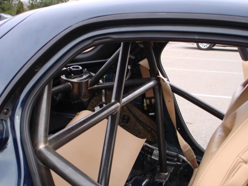
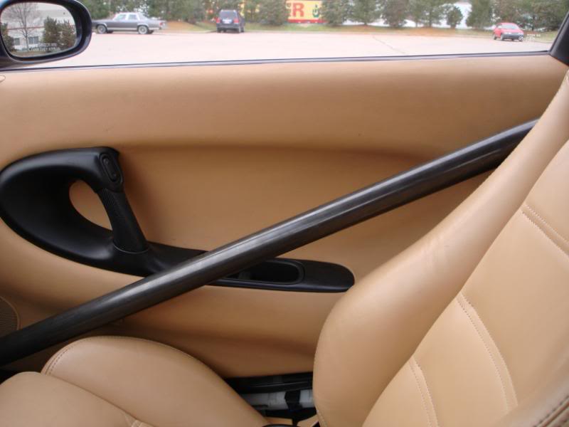

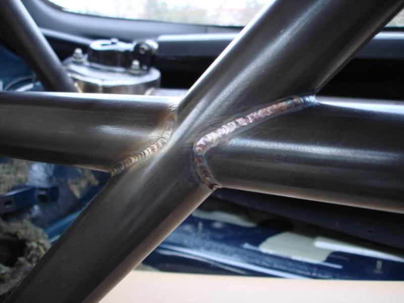
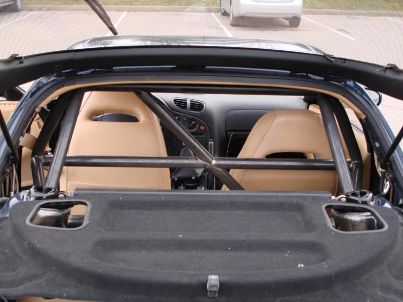
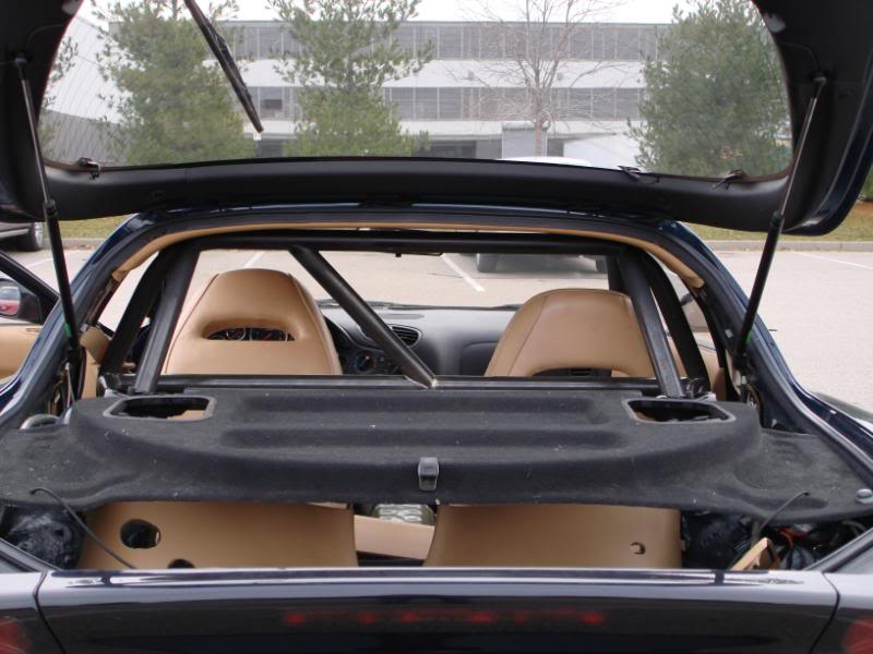
Lately I've been working on getting the interior ready to go back in. I had to split several pannels. Both rear quarter trim pannels had to be split to go around the roll bar tubing. The rear bucket had to be split in half to fit in the car. With all the tubes, it just wouldn't fit into the car at all. I also had to make some cuts in the pannel to get the main hoop and diagnal to fit around it.
The quarter pannels I split, and will be reconnectin them with aluminum rivets. On the back side there is a piece of sheet aluminum that the rivets go through. Here are a few pics of that. I will be puttin some rubber edge molding (bulb style) on the quarter trim pannels where the roll bar tubing goes through it. I think that the molding should seal the gap I have and look pretty nice. This is when it would pay off to have a black interior.

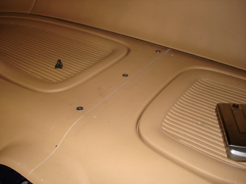
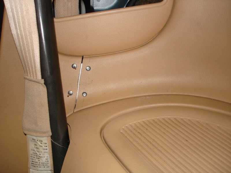
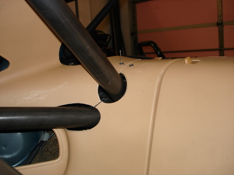
The car is way too loud on the inside, so I removed all the factory sound deadening, ~12 lbs. I replaced that with 20 lbs of dynamat extreme. I dynamatted the entire trunk area, rear bucket area, tunnel, and floorboards. I will also be addin some dynaliner to the tunnel, and a dynapad to the trunk area. I'll add another 12 lbs with all that stuff, but I don't really care. The car was just way too loud to enjoy as a daily driver. And some pics.
The following users liked this post:
tomatoto (01-02-20)