LS1/FD Build Thread (the most detailed build thread on Earth)
 05-20-10, 09:22 AM
#26
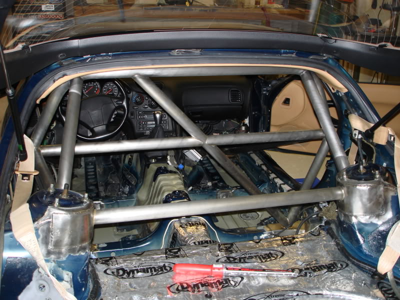
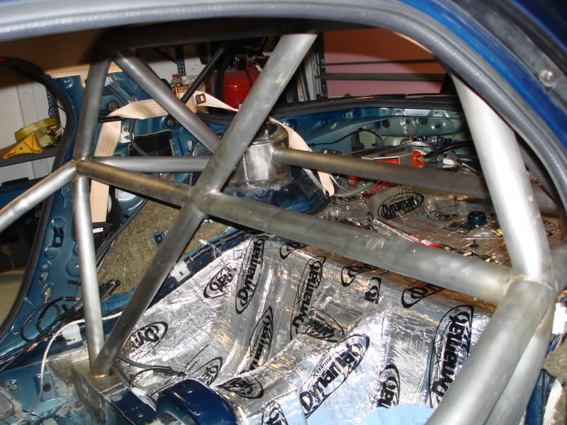
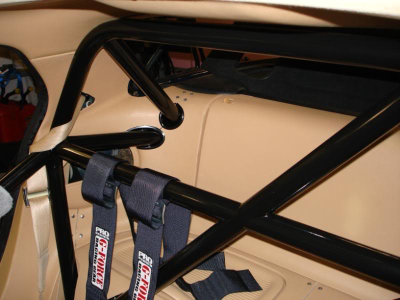
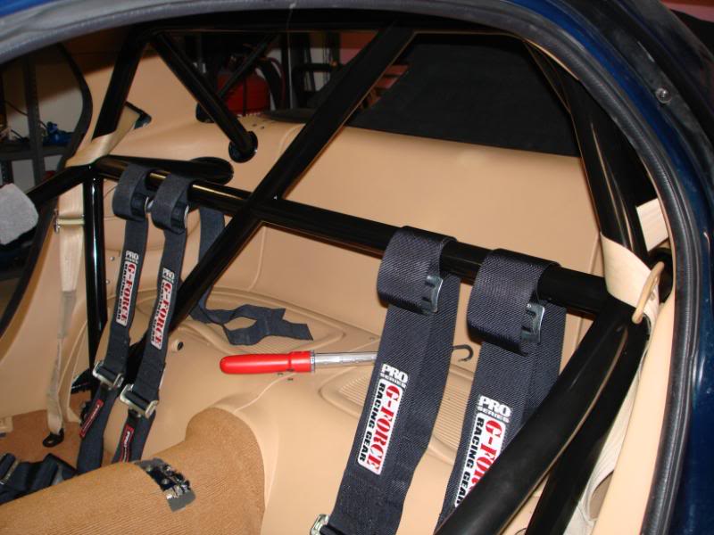
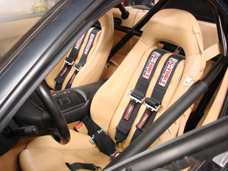
I also added mounting points for the 5 point harnesses. I added mount points for the lap bents and anti-submarining straps. For the shoulder belts I just wrapped them around the harness bar of my cage. Here are some pics.
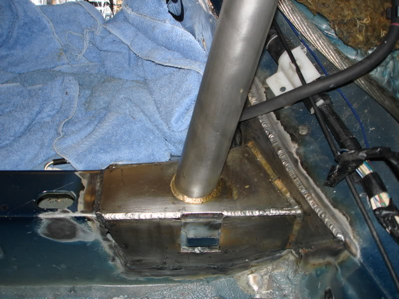
Inside lap belt plate.
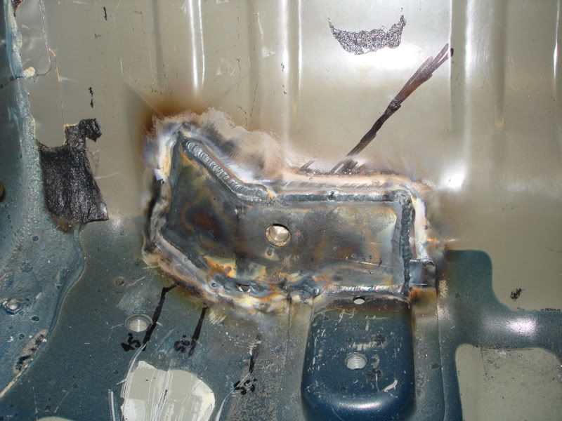
Outside lap belt plate.
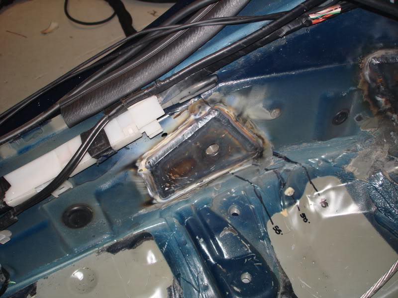
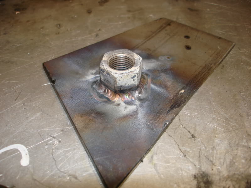
Nut welded to the back sided of the plate. I'm using 1/2" grade 8 fastners.
I guess I didn't snap a pic of the anti-sub belt mount this time. I'll get a pic of that later.
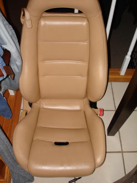
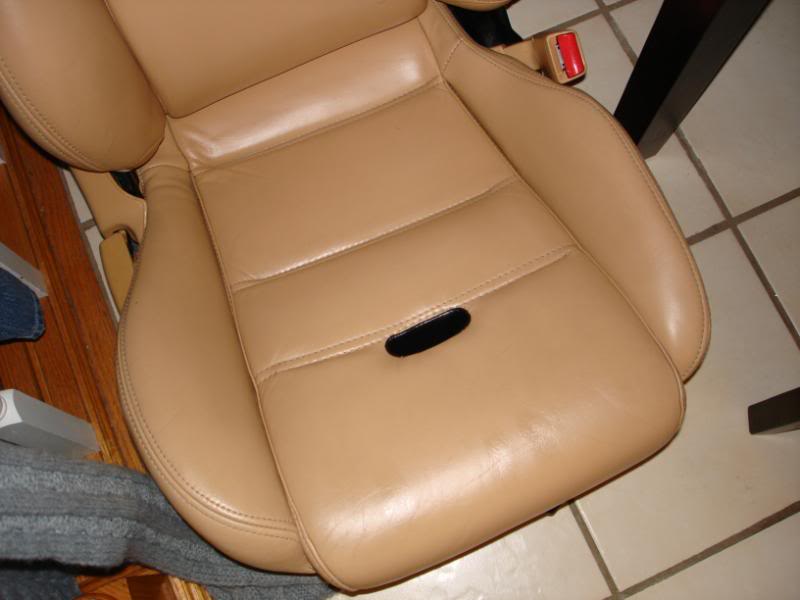
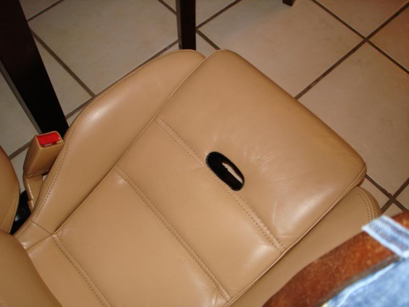
For the antisubmarining straps I needed a hole in teh seat, so I took my seats to a local upholstery shop (Edgetech Upholstery), and he did a very fine job on them. Pics.
8 hours, 16 purple scotch brite pads, and tired *** arms later the roll bar is prepped for paint. I removed all that dark grey coating. Por15 sticks best to bare metal.
All clean silver looking metal, scuffed ready for the por-15 process.
 05-20-10, 09:22 AM
#27
whew, I'm pooped out.
Today was fun filled with sound deading stuff.
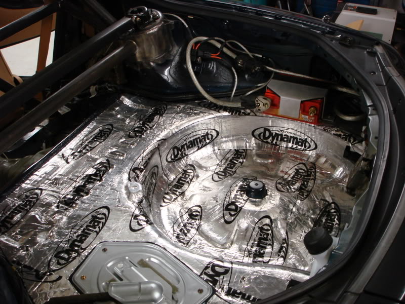
Since I don't have a spare tire anymore, I needed to fill that void in the trunk. I plan on making a custom carpet piece back there, so it must be flat. I decided I'd take advantage of that large area, and stuff it full of a sound deadening material. Sound absorbing foam was my choice. 1" thick. I bought it from McMaster. It has a NRC of 0.75. I layreed it 6 pieces deep, and cut them to fit inside the spare tire well. Then I used 3M spray adhesive to glue them all together.
Here is what it looks like.
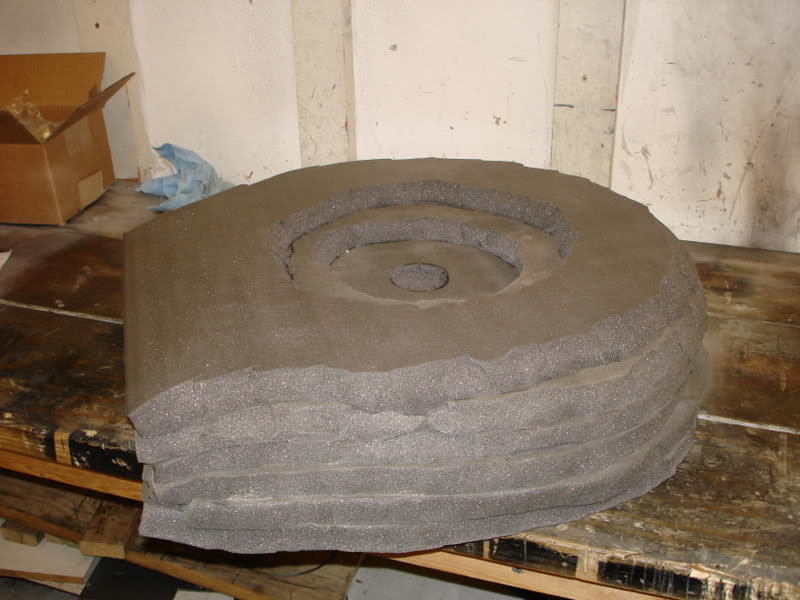
On top of that I will put another layer of 1" foam over the entire trunk for additional sound deadening, and to level out any countours and whatnot. Then on top of that goes the DynaPad. Then on top of that an ABS plastic piece wrapped in nice plush black carpet.
I think that should effectively make my car feel like a caddy on the inside. And hopefully my ears will thank me on those long drives. The foam is so light, its not even worth considering the weight gain. All the foam I'm going to be using is less than 3 lbs.
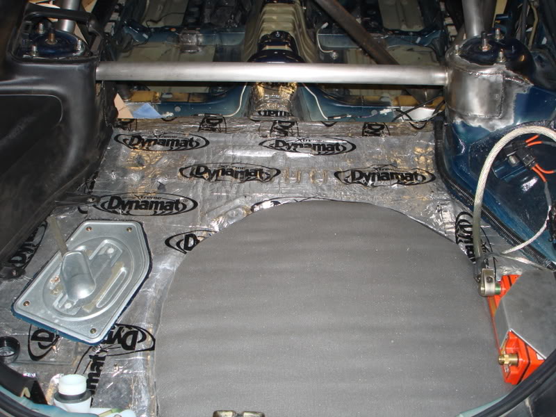
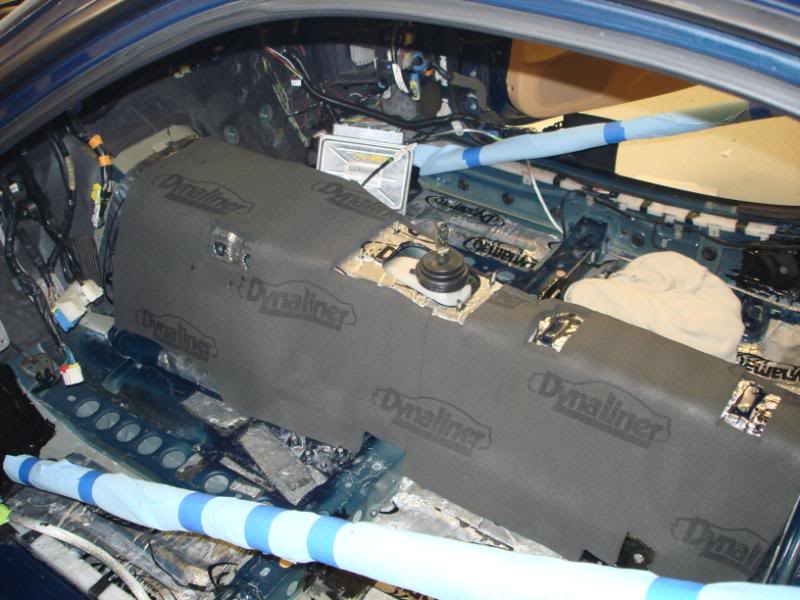
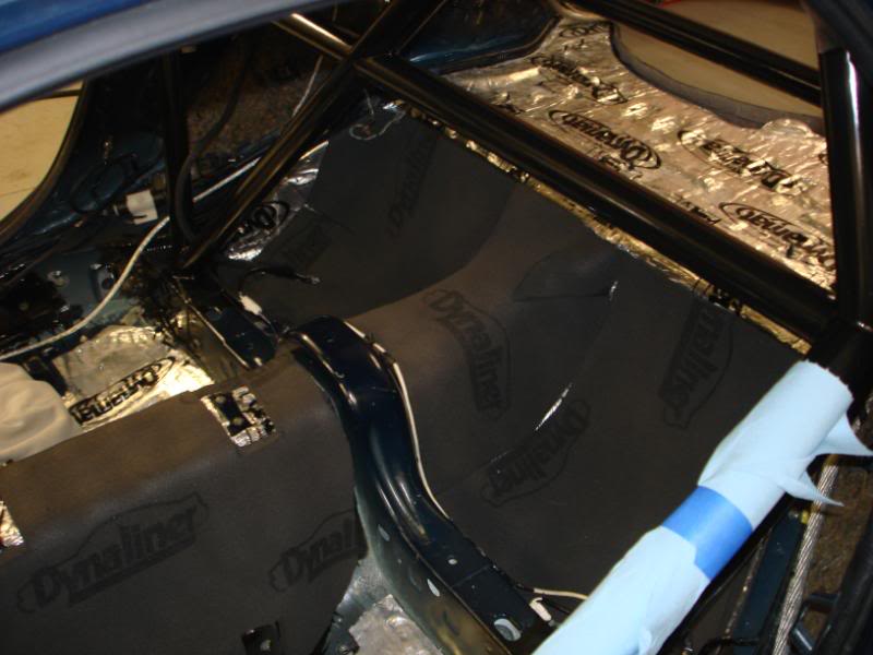
Then I started dynamattin the floorboards and trans tunnel. I'm going to the od the entire tunnel, then line that with DynaLiner to keep the tunnel heat off me.
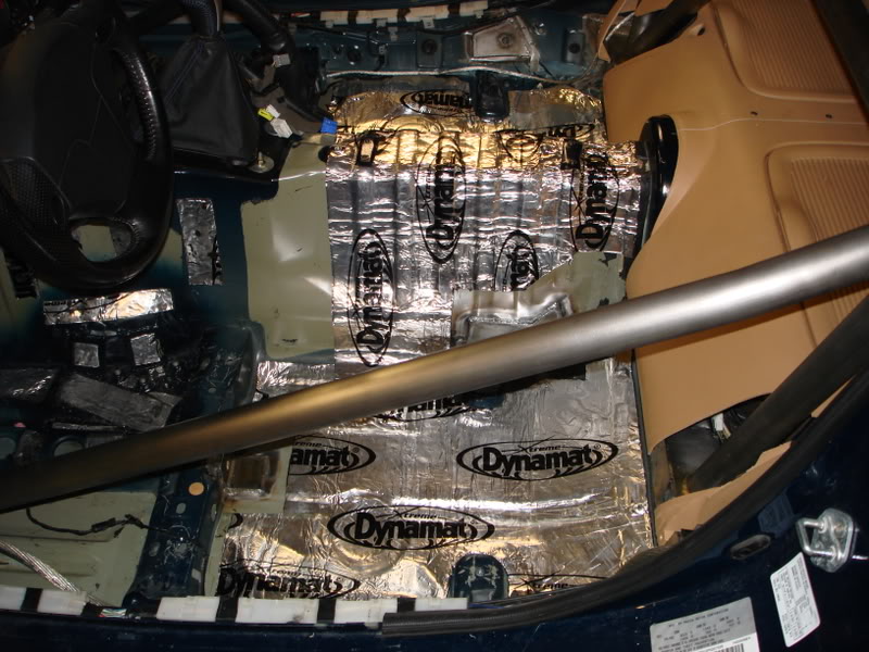
I added a layer of 1" sound absorbing foam to the entire flooroboard. I made some relief cuts on the underside to help level it out, for items that were sticking up a little. Then I cut the DynaPad to cover the entire floor. It acts like a sound barrier, and is supposed to really help with low frequency noise. There is a solid core, sandwitched between foam. The core absorbs the sound waves, vibrates, and it absorbed into the surrounding. Aparently its the ****, or so I'm told.
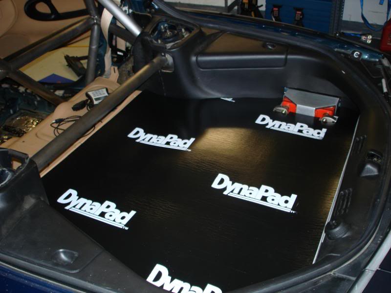
Coat 1: Check.
I'm impressed with how it looks. Just like I remember it. Took like 2 hours just for one coat though, and I've got three more to to before its all done.
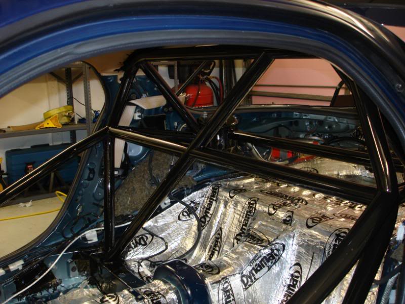
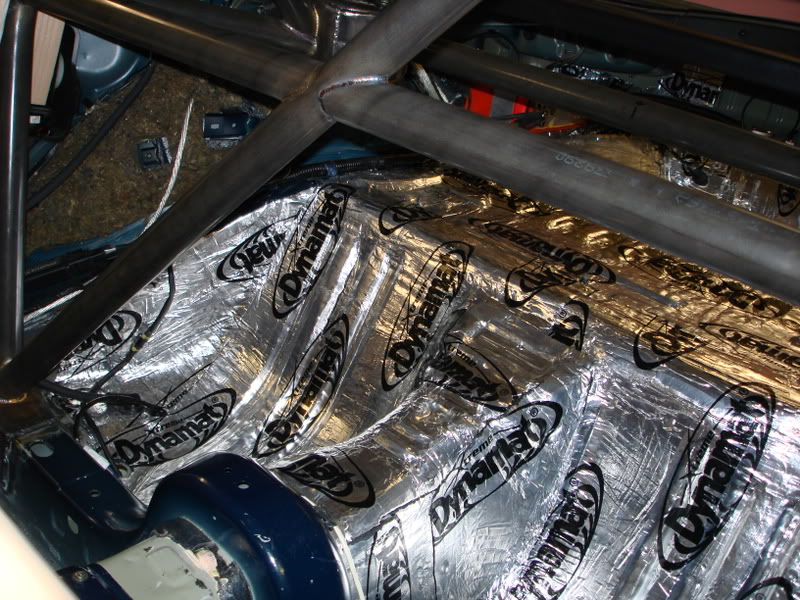
I put the next layer of sound deadening over the trans tunnel and in the buckets behind the seats. I used DynaLiner, 1/2" thick. It is also a thermal barrier. I wanted to put it to the test before I used it.
Here is the link to the info sheet for DynaLiner.
http://dynamat.com/download/specs/22..._Dynaliner.pdf
I was extremely bored, so I decided to make a video of my testing, and play around with the windows movie maker thing since I've never really used it before. Here it is.

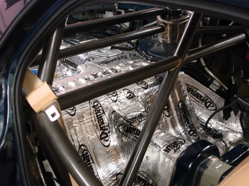
Cut holes in the carpet for the roll bar tubes.
Rear hole
Today was fun filled with sound deading stuff.
Since I don't have a spare tire anymore, I needed to fill that void in the trunk. I plan on making a custom carpet piece back there, so it must be flat. I decided I'd take advantage of that large area, and stuff it full of a sound deadening material. Sound absorbing foam was my choice. 1" thick. I bought it from McMaster. It has a NRC of 0.75. I layreed it 6 pieces deep, and cut them to fit inside the spare tire well. Then I used 3M spray adhesive to glue them all together.
Here is what it looks like.
On top of that I will put another layer of 1" foam over the entire trunk for additional sound deadening, and to level out any countours and whatnot. Then on top of that goes the DynaPad. Then on top of that an ABS plastic piece wrapped in nice plush black carpet.
I think that should effectively make my car feel like a caddy on the inside. And hopefully my ears will thank me on those long drives. The foam is so light, its not even worth considering the weight gain. All the foam I'm going to be using is less than 3 lbs.
Then I started dynamattin the floorboards and trans tunnel. I'm going to the od the entire tunnel, then line that with DynaLiner to keep the tunnel heat off me.
I added a layer of 1" sound absorbing foam to the entire flooroboard. I made some relief cuts on the underside to help level it out, for items that were sticking up a little. Then I cut the DynaPad to cover the entire floor. It acts like a sound barrier, and is supposed to really help with low frequency noise. There is a solid core, sandwitched between foam. The core absorbs the sound waves, vibrates, and it absorbed into the surrounding. Aparently its the ****, or so I'm told.
Coat 1: Check.
I'm impressed with how it looks. Just like I remember it. Took like 2 hours just for one coat though, and I've got three more to to before its all done.
I put the next layer of sound deadening over the trans tunnel and in the buckets behind the seats. I used DynaLiner, 1/2" thick. It is also a thermal barrier. I wanted to put it to the test before I used it.
Here is the link to the info sheet for DynaLiner.
http://dynamat.com/download/specs/22..._Dynaliner.pdf
I was extremely bored, so I decided to make a video of my testing, and play around with the windows movie maker thing since I've never really used it before. Here it is.
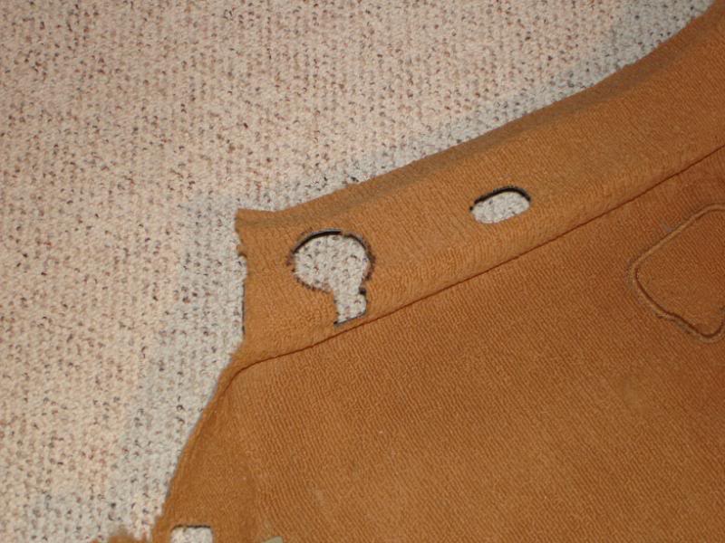
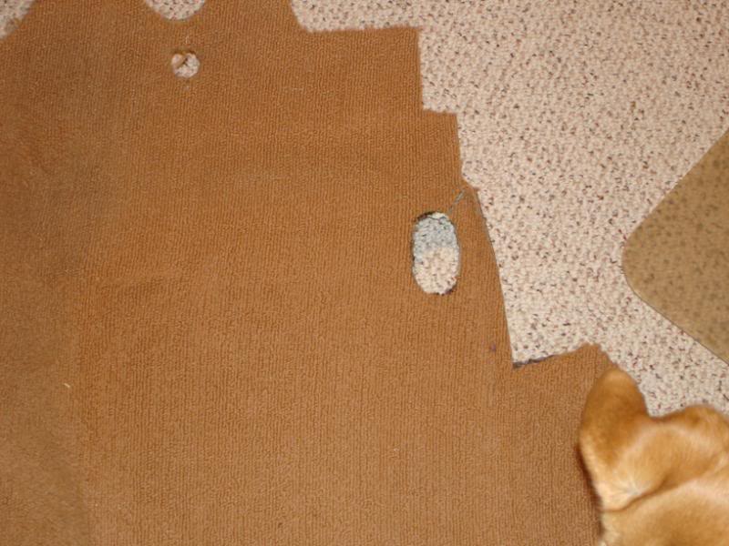
Cut holes in the carpet for the roll bar tubes.
Rear hole
05-20-10, 09:23 AM
#28
Front hole
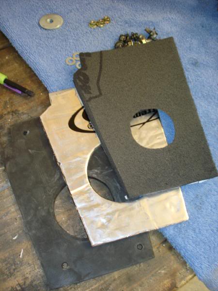
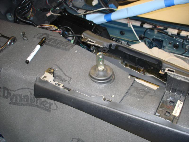
I made a cover for the shifter hole in the tunnel. Its 4 layers.
1. 3/16" thick neoprene rubber. I'm using this as a gasket.
2. 1/8" thick aluminum
3. Dynamat extreme
4. 1/2" thick Dyaliner. I made the hole in this smaller so it would hug the shifter boot well and make an "air tight" seal.
The dynamat is on the aluminum in this pic.
and installed
I put 1/4" dynaliner on the inside of all the rear pannels.
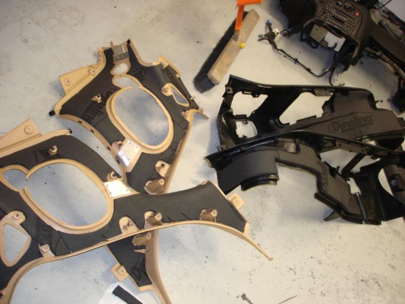
Then started stuffing the 1" thick sound deadening foam into every space available.
I'll definately be out and about.
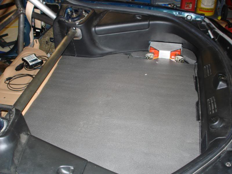
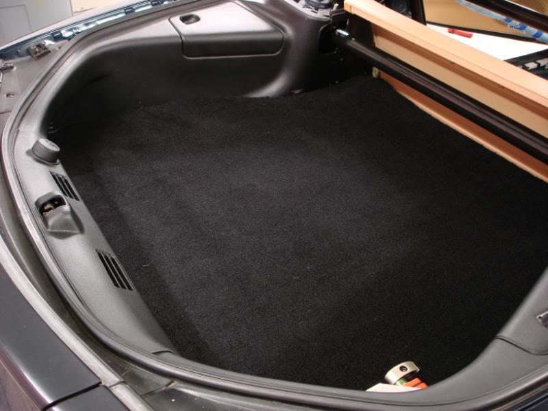
And the rear has reached completion. Well, mostly. I got the carpet cut and fit in there. I just need to take it to the upholestry shop and get some edging sewn on. Looks nearly stock other than the battery, and I left that exposed for easy access. I think some black powercoating on the bracket might be in order.

Mo progress.
I got the interior mostly in. Just finishing up a few last things till the seats and center concole go in.
I'm also making some door bar covers for the door bar tubing. The covers serve several purposes.
1. Padding to prevent elbow shattering.
2. Prevent paint from looking like **** in 1 month.
3. Keep the cold bars off my arms when its cold out.
So I went to my mother seeking sewing lessons. She taught me out to do a few stitches and how to adjust the machine for my application.
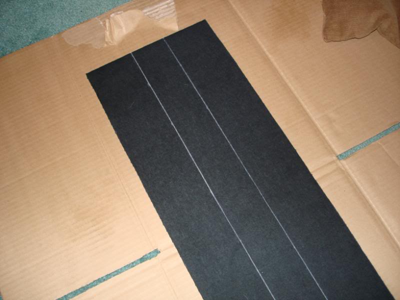
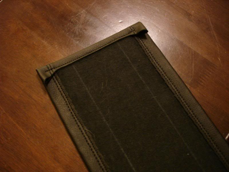
I am using a Rave brand vinyl, which is very leather like. Very soft, very durable. I purchased from Miami Rubber Corp. I also purchased some UV resistant black nylon thread. Its much stronger than standard cotton thread. Under the vinly will be a 3/16" piece of neoprene rubber. I made quite a few practice pieces and basically taught myself how to sew in a day or so. Then onto the actual pieces.
Cutting out the piece and marking lines to fold on.
Folded over and sewed. I made two passes on each side for extra strength.
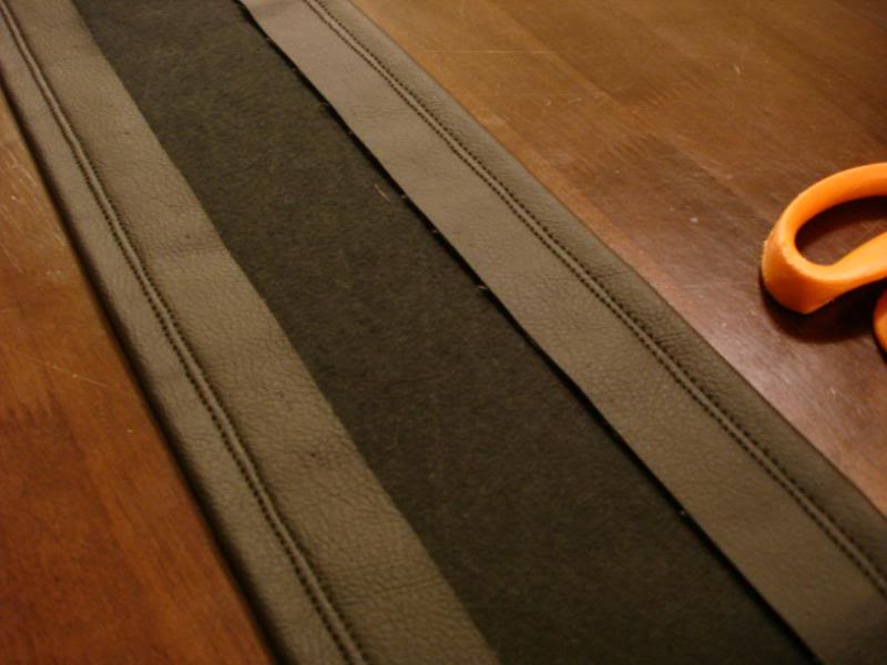
Excess trimmed off, and edge folded over and sewn down.
I made a cover for the shifter hole in the tunnel. Its 4 layers.
1. 3/16" thick neoprene rubber. I'm using this as a gasket.
2. 1/8" thick aluminum
3. Dynamat extreme
4. 1/2" thick Dyaliner. I made the hole in this smaller so it would hug the shifter boot well and make an "air tight" seal.
The dynamat is on the aluminum in this pic.
and installed
I put 1/4" dynaliner on the inside of all the rear pannels.
Then started stuffing the 1" thick sound deadening foam into every space available.
I'll definately be out and about.
And the rear has reached completion. Well, mostly. I got the carpet cut and fit in there. I just need to take it to the upholestry shop and get some edging sewn on. Looks nearly stock other than the battery, and I left that exposed for easy access. I think some black powercoating on the bracket might be in order.
Mo progress.
I got the interior mostly in. Just finishing up a few last things till the seats and center concole go in.
I'm also making some door bar covers for the door bar tubing. The covers serve several purposes.
1. Padding to prevent elbow shattering.
2. Prevent paint from looking like **** in 1 month.
3. Keep the cold bars off my arms when its cold out.
So I went to my mother seeking sewing lessons. She taught me out to do a few stitches and how to adjust the machine for my application.
I am using a Rave brand vinyl, which is very leather like. Very soft, very durable. I purchased from Miami Rubber Corp. I also purchased some UV resistant black nylon thread. Its much stronger than standard cotton thread. Under the vinly will be a 3/16" piece of neoprene rubber. I made quite a few practice pieces and basically taught myself how to sew in a day or so. Then onto the actual pieces.
Cutting out the piece and marking lines to fold on.
Folded over and sewed. I made two passes on each side for extra strength.
Excess trimmed off, and edge folded over and sewn down.
05-20-10, 09:24 AM
#29
Slits cut and metal rods inserted.
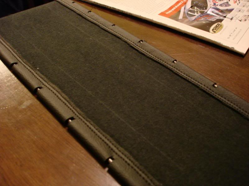
Last edge sewn shut, and metal rods are now stuck inside.
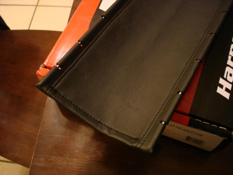
I'll be using the metal rods to tighten this down on the rubber/door bar. I did a few trial pieces and it held it in place very strong. I'll probably have it installed tomorrow and pics will follow. Once those are on, the seats and center console go in. Then I'm done.
Side note, I added a circuit to my tach wiring and now it works. Yay!
I got the reminder of the interior installed today. Such a weight off my back.
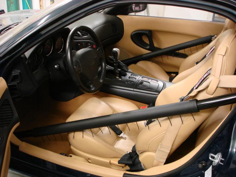
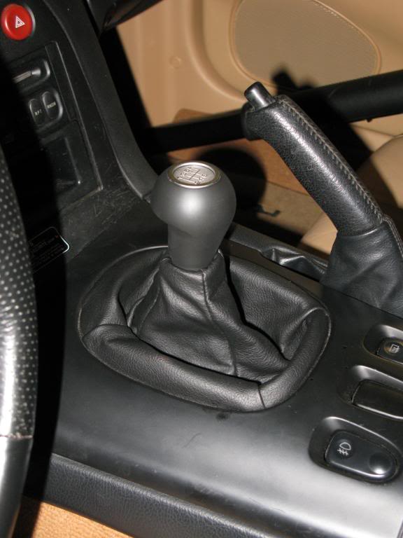
The little strings hanging off roll bar padding will be cut off. I'm waiting a few days for the material to stretch, and retighten before I cut them off.
*Note the retardedly tall shifter. I HAVE to do something about that asap! LOL.
This build thread is ~3 years old and there is a lot that has been changed since then. I'll see if I can find some of those posst to update.
Last edge sewn shut, and metal rods are now stuck inside.
I'll be using the metal rods to tighten this down on the rubber/door bar. I did a few trial pieces and it held it in place very strong. I'll probably have it installed tomorrow and pics will follow. Once those are on, the seats and center console go in. Then I'm done.
Side note, I added a circuit to my tach wiring and now it works. Yay!
I got the reminder of the interior installed today. Such a weight off my back.
The little strings hanging off roll bar padding will be cut off. I'm waiting a few days for the material to stretch, and retighten before I cut them off.
*Note the retardedly tall shifter. I HAVE to do something about that asap! LOL.
This build thread is ~3 years old and there is a lot that has been changed since then. I'll see if I can find some of those posst to update.
05-20-10, 09:27 AM
#30
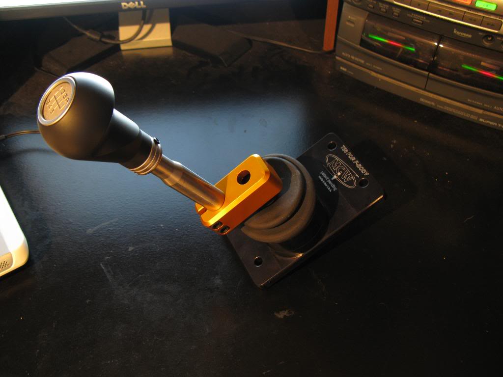
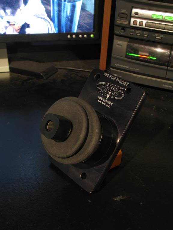
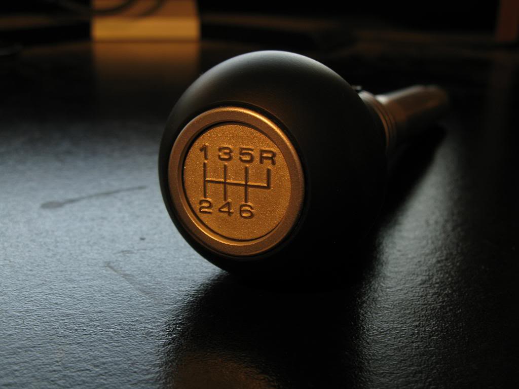
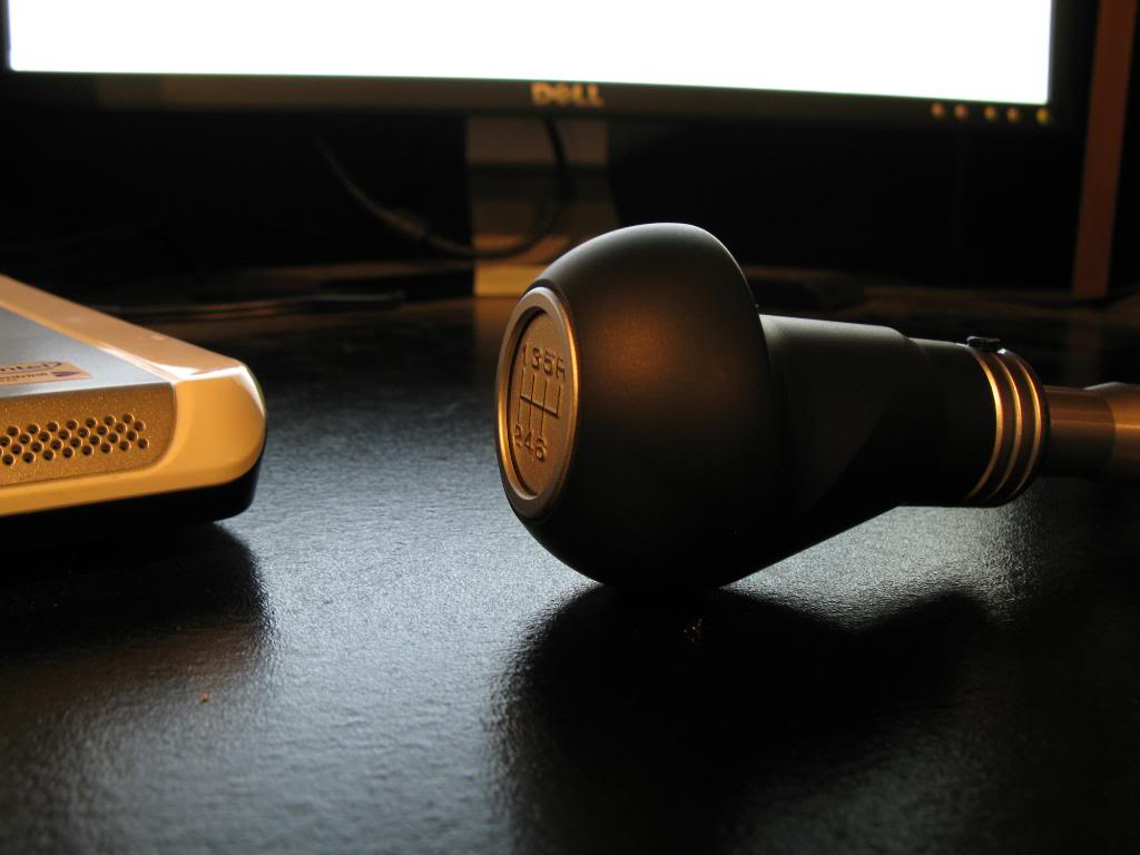
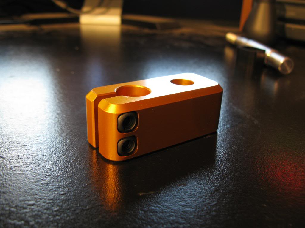
I purchased an MGW shifter for an F-body, to retrofit onto my transmission (GTO trans). After swapping the offset lever in the trans, the F-body shifters bolt up no problem. Here are some pics of this shifter. Looks like a high quality piece for sure. Here are some pics from my point and shoot.
This is the entire thing. Normally on an F-body the goldish colored piece is offset towards the left (drivers side), but for my application I'm going to clock it downward (toward the rear of the car).
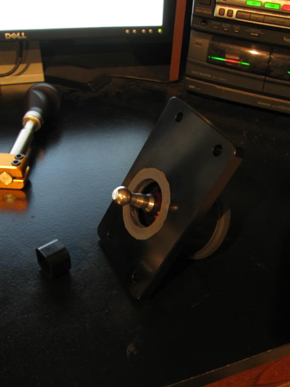
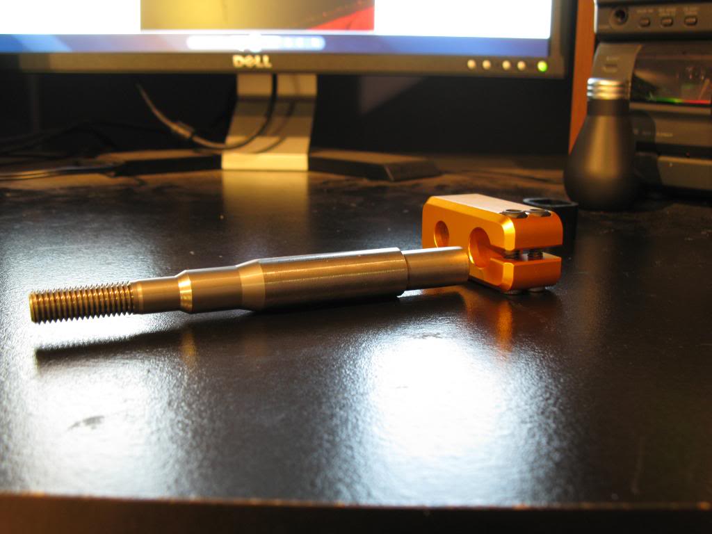
Main shifter piece with the offset piece removed.
Underside of the shifter showing the actual lever ball that inserts into the transmission.
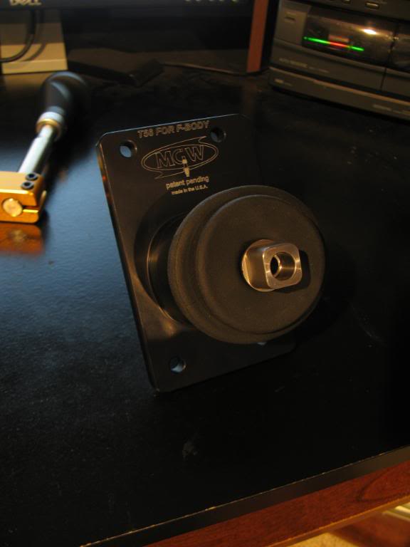
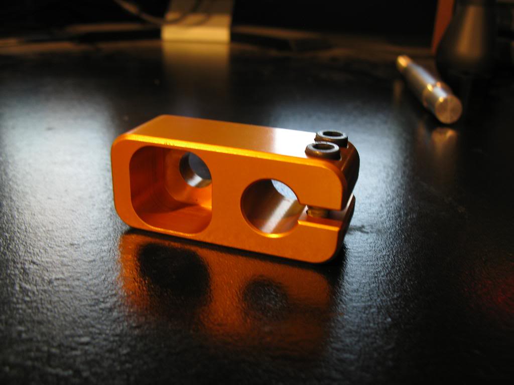
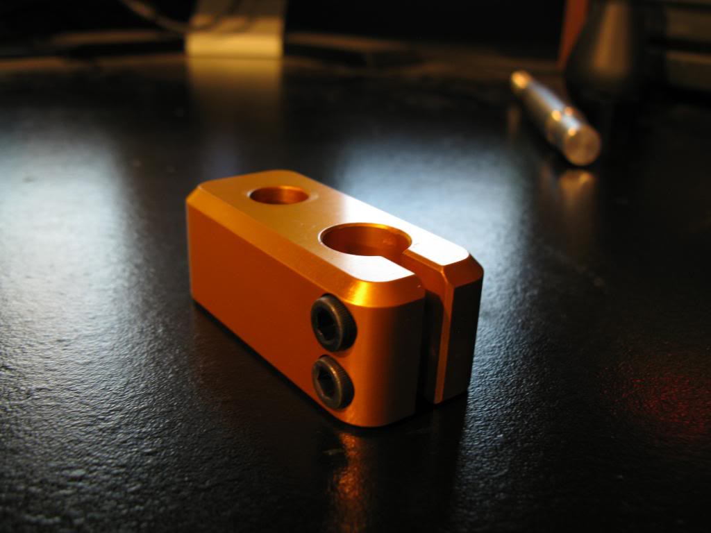
Offset block with bushing shown. The bushing is a pretty high durometer rubber (maybe 60, can't recall what the tech said), and is very stiff. As you can see, it fits into the gold offset block.
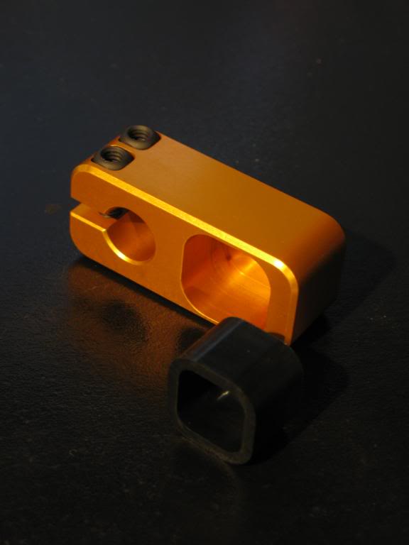
Rubber bushing on the shifter. When you install the gold offset block onto the shifter with the bushing in there, its a pretty decent interference fit, so much so that you have to pull it in with the top bolt (not shown). The rubber is very compressed, and you can't even tell there is rubber there, it feels solid. However even a small bit of high durometer rubber does wonders to NVH.
Offset block and shift lever. As you can see the shift lever has a stop when you insert it into the offset block. Then you tighten down the two bolts on the block. For my application, I'm going to have to turn that shift lever down about 2.25" shorter.
And the shift **** that I ordered as well. Its an MGW ****, the "Mustang Composite Race ****". I actually ordered the "corvette race ****" but this came and I really like the way it feels, I think I may keep it. It fits the 12mm threads that are on the shaft. You can also request 16mm threads if you want.
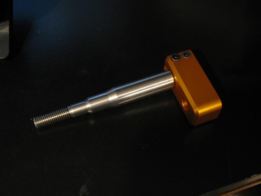
And some more closeup pictures of the gold offset block. I'm not sure that this offset block will put the shifter back as far as I need it. If it does not move it back as much as I'd like, I'll have to get a custom offset block made, with more space betwen the shift hole, and the bushing hole. If anyone works at a machine shop and would like to take a look at this for me, I'll likely need to have one made. And of course I pay, but dont' want to pay an arm and a leg. Let me know if you can help me out. Some closeup pics to see more details on it.
This is the entire thing. Normally on an F-body the goldish colored piece is offset towards the left (drivers side), but for my application I'm going to clock it downward (toward the rear of the car).
Main shifter piece with the offset piece removed.
Underside of the shifter showing the actual lever ball that inserts into the transmission.
Offset block with bushing shown. The bushing is a pretty high durometer rubber (maybe 60, can't recall what the tech said), and is very stiff. As you can see, it fits into the gold offset block.
Rubber bushing on the shifter. When you install the gold offset block onto the shifter with the bushing in there, its a pretty decent interference fit, so much so that you have to pull it in with the top bolt (not shown). The rubber is very compressed, and you can't even tell there is rubber there, it feels solid. However even a small bit of high durometer rubber does wonders to NVH.
Offset block and shift lever. As you can see the shift lever has a stop when you insert it into the offset block. Then you tighten down the two bolts on the block. For my application, I'm going to have to turn that shift lever down about 2.25" shorter.
And the shift **** that I ordered as well. Its an MGW ****, the "Mustang Composite Race ****". I actually ordered the "corvette race ****" but this came and I really like the way it feels, I think I may keep it. It fits the 12mm threads that are on the shaft. You can also request 16mm threads if you want.
And some more closeup pictures of the gold offset block. I'm not sure that this offset block will put the shifter back as far as I need it. If it does not move it back as much as I'd like, I'll have to get a custom offset block made, with more space betwen the shift hole, and the bushing hole. If anyone works at a machine shop and would like to take a look at this for me, I'll likely need to have one made. And of course I pay, but dont' want to pay an arm and a leg. Let me know if you can help me out. Some closeup pics to see more details on it.
05-20-10, 09:28 AM
#31
Finally, installed, kinda. Its not sealed up, but the mockup is done. If it weren't a custom application it would have already been done.
Here is the difference in the offset levers between the GTO and the F-body one. The GTO is on the right, F-body on hte left. That is teh piece that the actual shifter sticks into.
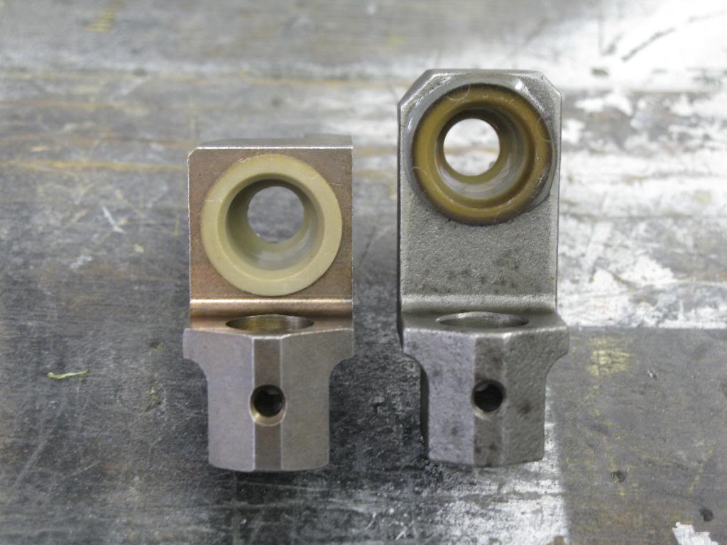
As I said before, I needed more offset to get the shifter to where I wanted, and I also wanted to shorten the shift lever. I was going to machine a new offset block, and also turn down the shift lever. Instead of all that machine time I decided to just get the job done by modifying the shift lever itself. I chopped it and offset it, using some 1/8" stainless plate, boxing it is. Super strong, and does the job. Its 1.5" further back, and 1.5" shorter than before. Looks kinda shity in my opinion, but it was free and I dind't have to spend like 10 hours in a machine shop making a new block. The washers are welded together, and onto the shaft to make a large enough diameter for my boot to attach to. The washers are around the actual shaft, its not just a bunch of washers stacked up to make a shaft, lol. I dind't feel like making another custom shift boot again, so I ghetto fabbed it up.
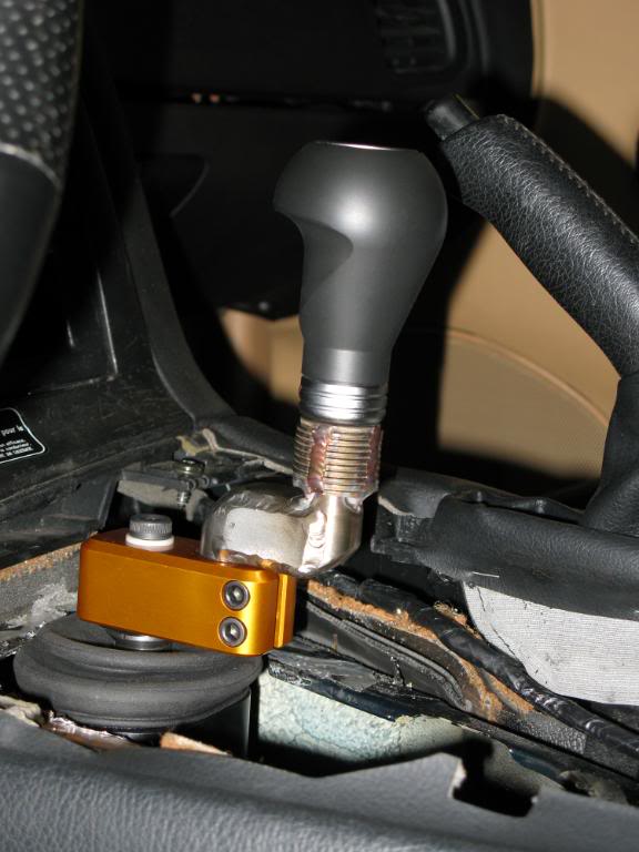
And all done with the boot on.
Here is the difference in the offset levers between the GTO and the F-body one. The GTO is on the right, F-body on hte left. That is teh piece that the actual shifter sticks into.
As I said before, I needed more offset to get the shifter to where I wanted, and I also wanted to shorten the shift lever. I was going to machine a new offset block, and also turn down the shift lever. Instead of all that machine time I decided to just get the job done by modifying the shift lever itself. I chopped it and offset it, using some 1/8" stainless plate, boxing it is. Super strong, and does the job. Its 1.5" further back, and 1.5" shorter than before. Looks kinda shity in my opinion, but it was free and I dind't have to spend like 10 hours in a machine shop making a new block. The washers are welded together, and onto the shaft to make a large enough diameter for my boot to attach to. The washers are around the actual shaft, its not just a bunch of washers stacked up to make a shaft, lol. I dind't feel like making another custom shift boot again, so I ghetto fabbed it up.
And all done with the boot on.
05-20-10, 09:57 AM
#32
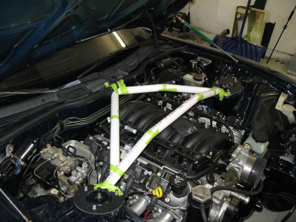
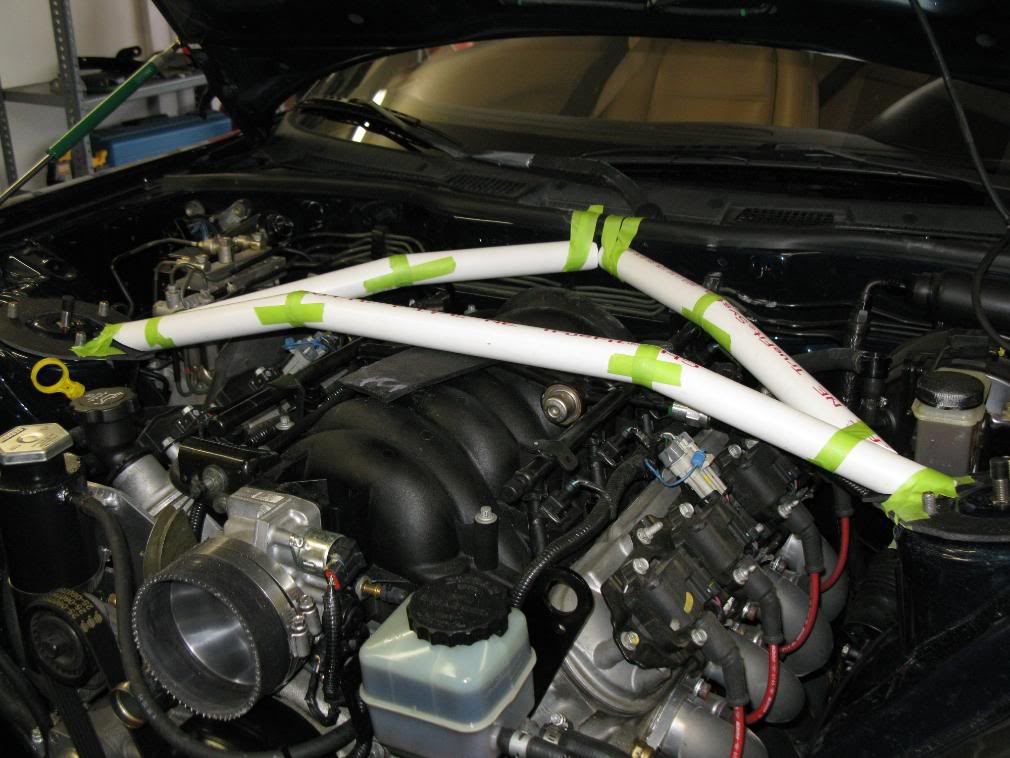
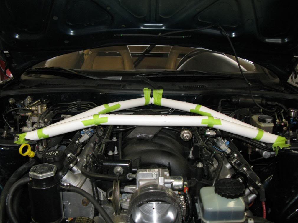
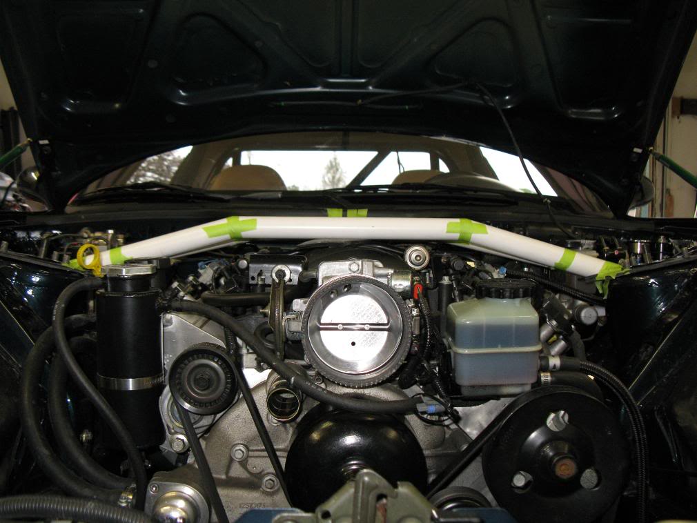
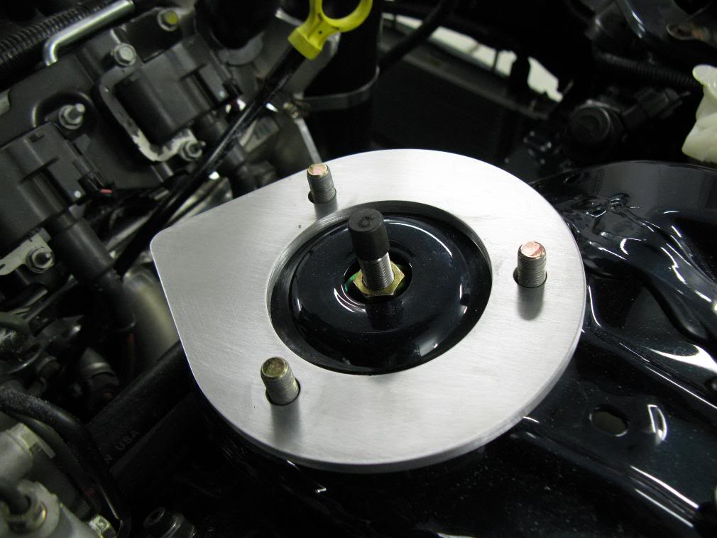
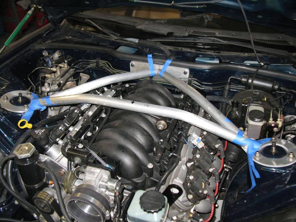
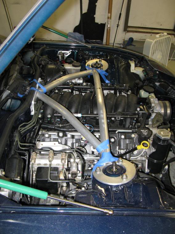
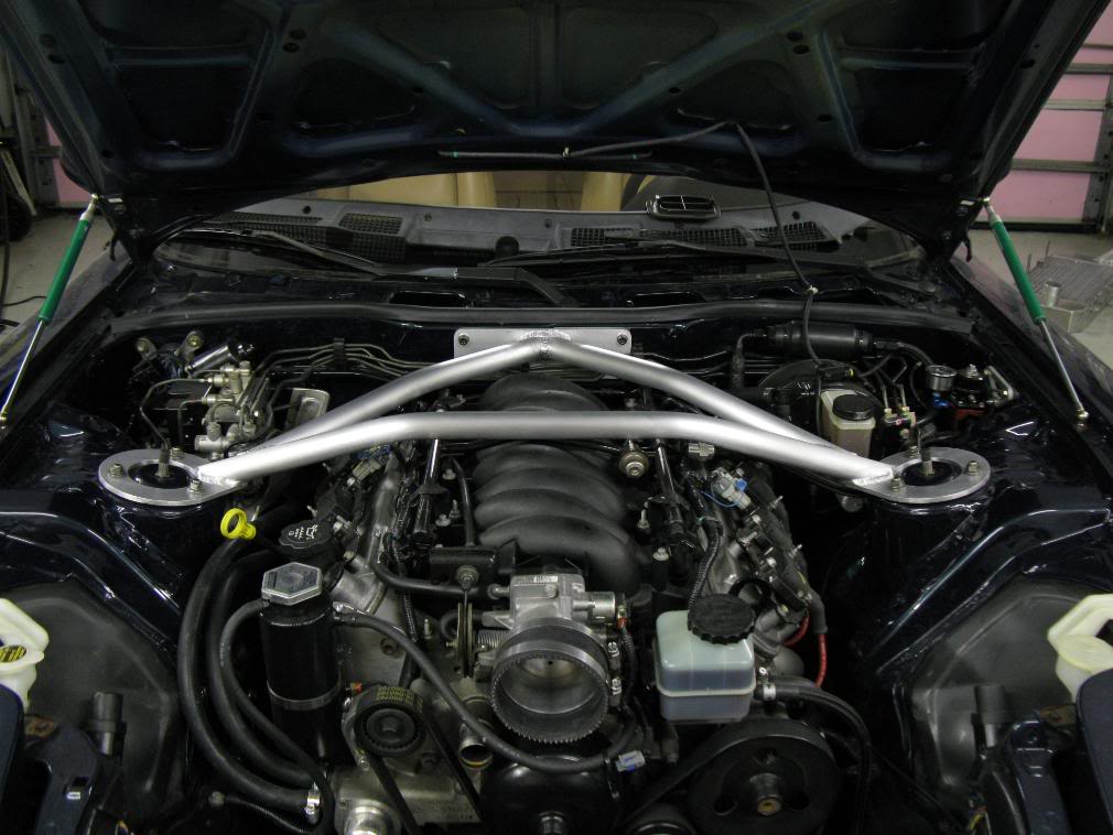
Well I was getting kinda bored with nothing to work on lately so I've been thinking of stuff that I could make for my car. I ended up ordering some parts to start making a front underbody pannel and splitter. While I'm waiting on those parts I figured it start mocking up a front strut tower bar.
I'm mocking it up with 1" schedule 40 PVC. It ends up being 1.33" OD and 0.133" wall thickness. I'll probalby end up using 1" sch 40 AL pipe, or maybe sch 80, not sure. I also used some 1/4" foam board for the tower mounts but that will end up being water jet cut from 1/4" 6061-T6 1/4" plate.
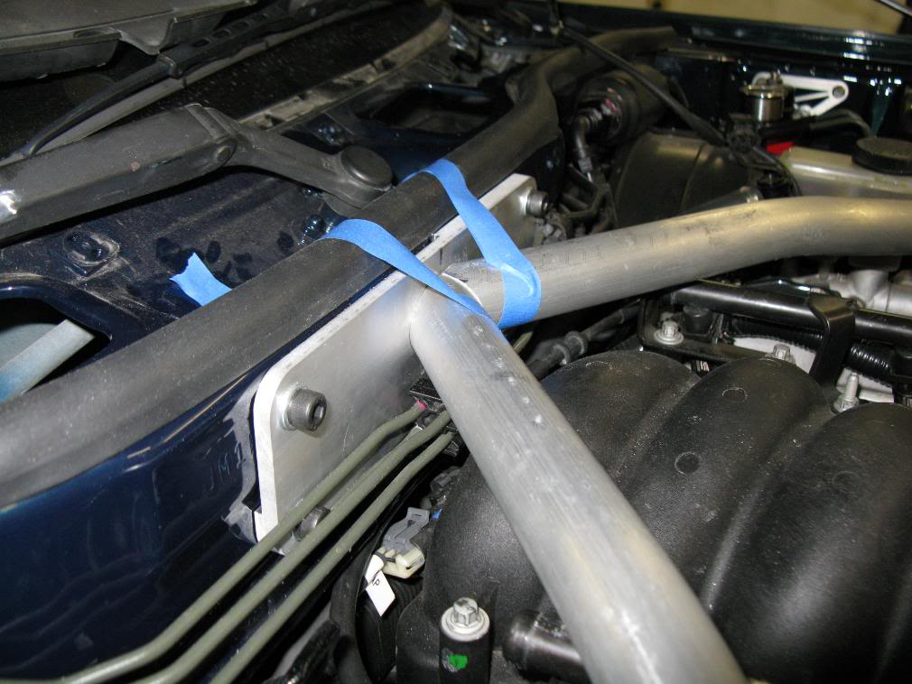
I started the mockup using 1.5" aluminum tube but it ended up being too large of an OD. As it sits now, I have ~3/16" clearnace from the hood at the closest, and 5/16" clearance from the LS6 manifold. at the closest point. For the firewall connection I'm going to be using a pretty large 1/4" aluminum plate to spread the load out, bolted to the firewall using nutserts and bolts. The pictures show the PVC being cut and taped. On the real version this will be a bent tube.
The main tube has two 15 degree bends in it to avoid hitting the webing under the hood, and I cannot go less w/o hitting the hood. The bars going to the firewall have a 10 degree bend in them, and that is to clear the fuel rails.
Nothing is set in stone right now, so if you have any ideas on places to improve let me know.
And pics:
I'm mocking it up with 1" schedule 40 PVC. It ends up being 1.33" OD and 0.133" wall thickness. I'll probalby end up using 1" sch 40 AL pipe, or maybe sch 80, not sure. I also used some 1/4" foam board for the tower mounts but that will end up being water jet cut from 1/4" 6061-T6 1/4" plate.
I started the mockup using 1.5" aluminum tube but it ended up being too large of an OD. As it sits now, I have ~3/16" clearnace from the hood at the closest, and 5/16" clearance from the LS6 manifold. at the closest point. For the firewall connection I'm going to be using a pretty large 1/4" aluminum plate to spread the load out, bolted to the firewall using nutserts and bolts. The pictures show the PVC being cut and taped. On the real version this will be a bent tube.
The main tube has two 15 degree bends in it to avoid hitting the webing under the hood, and I cannot go less w/o hitting the hood. The bars going to the firewall have a 10 degree bend in them, and that is to clear the fuel rails.
Nothing is set in stone right now, so if you have any ideas on places to improve let me know.
And pics:
05-20-10, 09:59 AM
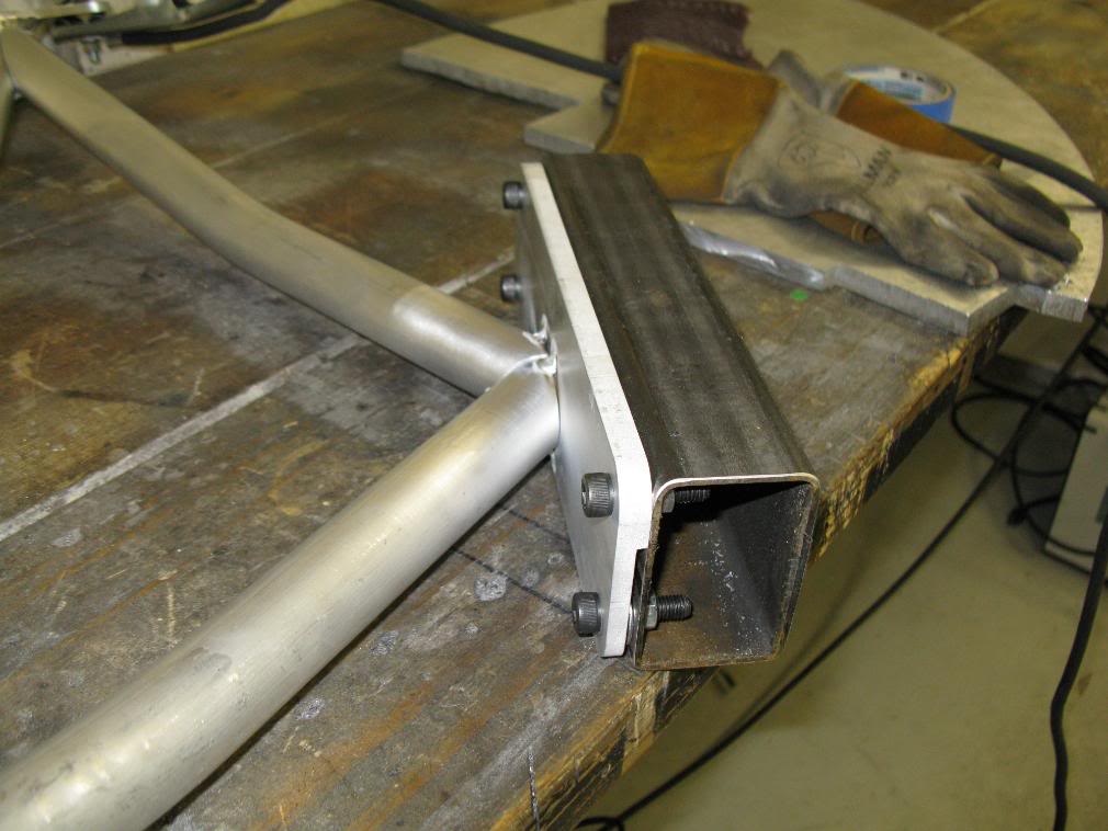
#33
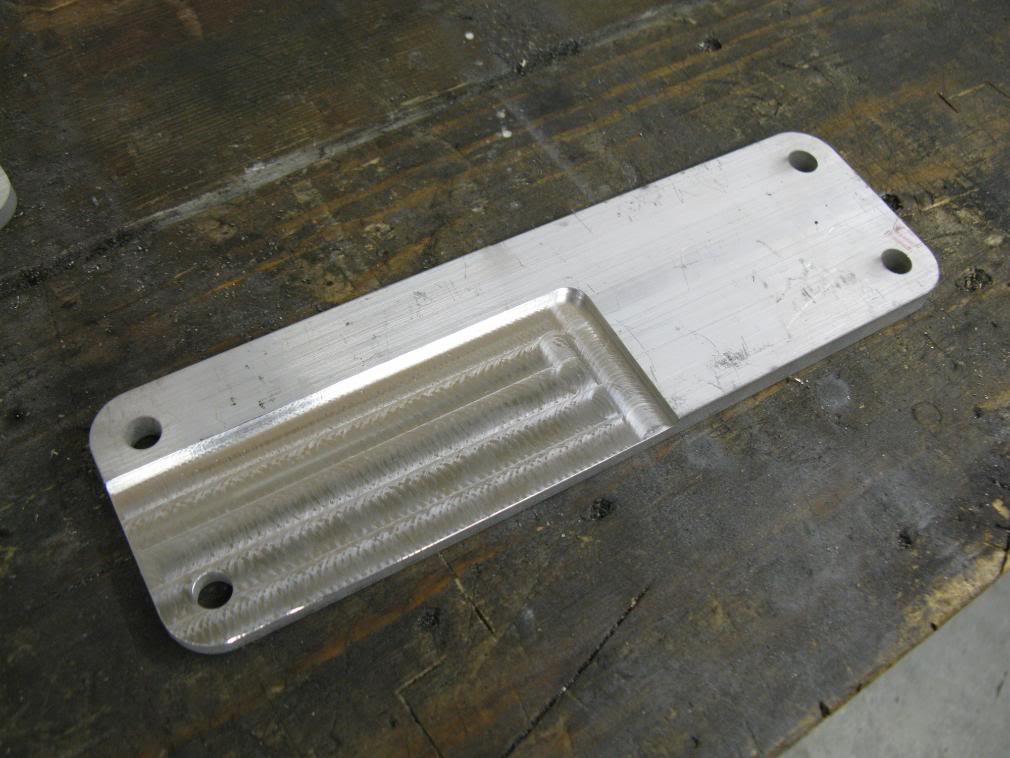
So the plates are all done, and fit well. Time to start some fabrication work on this bitch.
The cutout on the firewall plate is to clear the VIN boss, and make the plate sit flat on the firewall. Dave (JuicedH22) and I machined them, well I basically did, but dave reminded me how to use the mahince since it has been a really long time since I have used a milling machine.
The RB28TT was a joke to make fun of someone on my local forum.

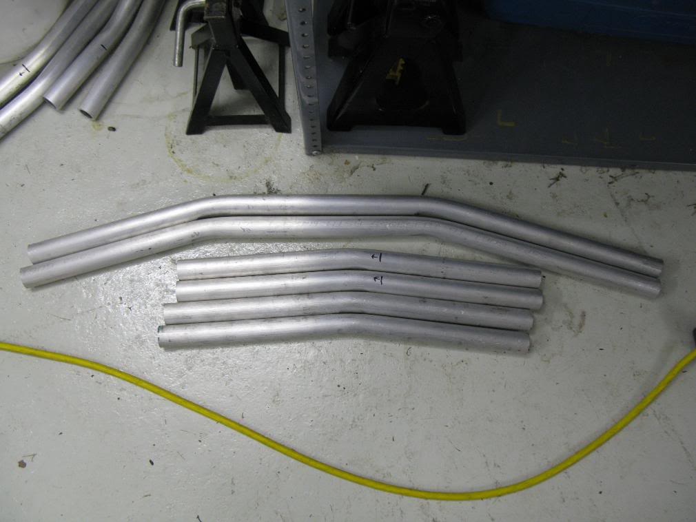
Rob @ Rigid bent up my pipe for me, and it turned out really good. Its some heady duty stuff. The pipe is not crushed on the inside of the bend, the dies just made the surface shiny so it appears to be dented.
The cutout on the firewall plate is to clear the VIN boss, and make the plate sit flat on the firewall. Dave (JuicedH22) and I machined them, well I basically did, but dave reminded me how to use the mahince since it has been a really long time since I have used a milling machine.
The RB28TT was a joke to make fun of someone on my local forum.
Rob @ Rigid bent up my pipe for me, and it turned out really good. Its some heady duty stuff. The pipe is not crushed on the inside of the bend, the dies just made the surface shiny so it appears to be dented.
05-20-10, 10:00 AM
#34
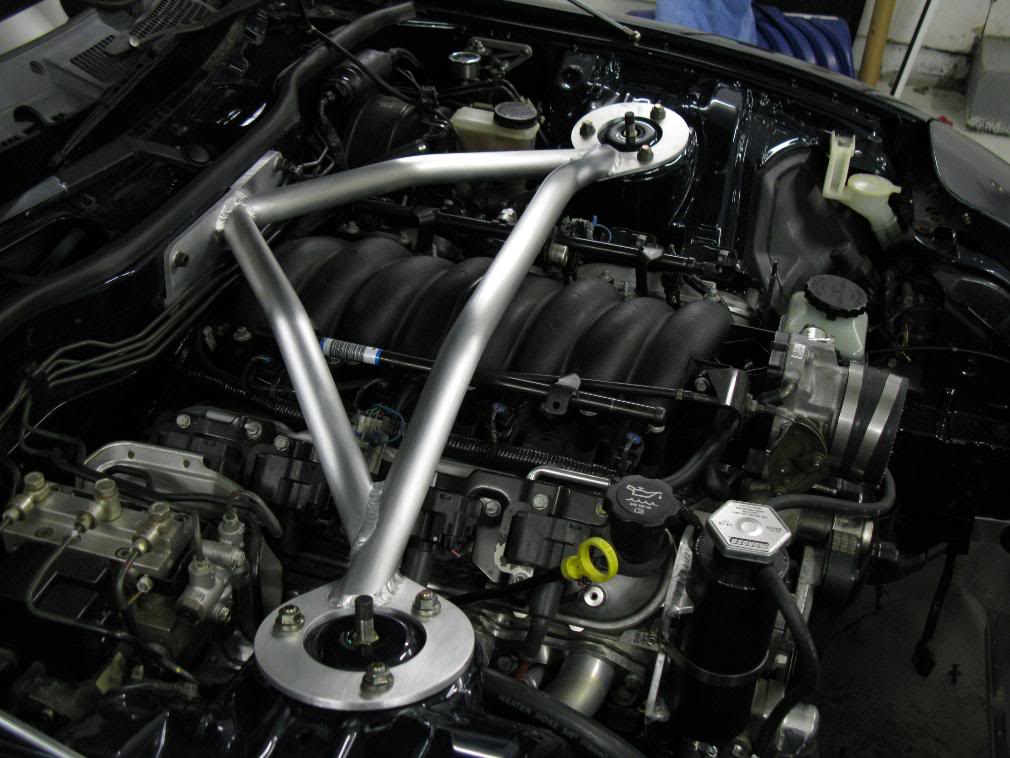
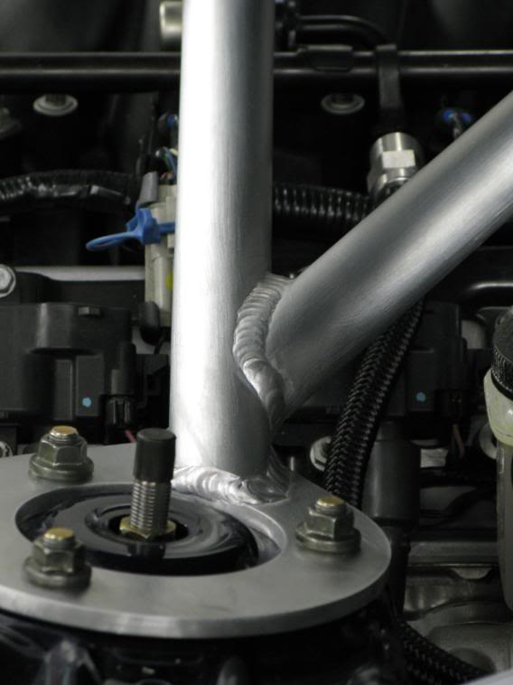
Today I made up the strut tower bar from the real deal. It took 10x longer than with the PVC, but all went well. No wasted pieces so thats a plus. All ready to weld tomorrow. I'm gonna have to do some thinking on what order to tack/weld the thing together to prevent warpage and bolt hole misalignment. I only made one change and that was to have the firewall tubes somewhat intersect each other. And onto the pics.
05-20-10, 10:01 AM
#35
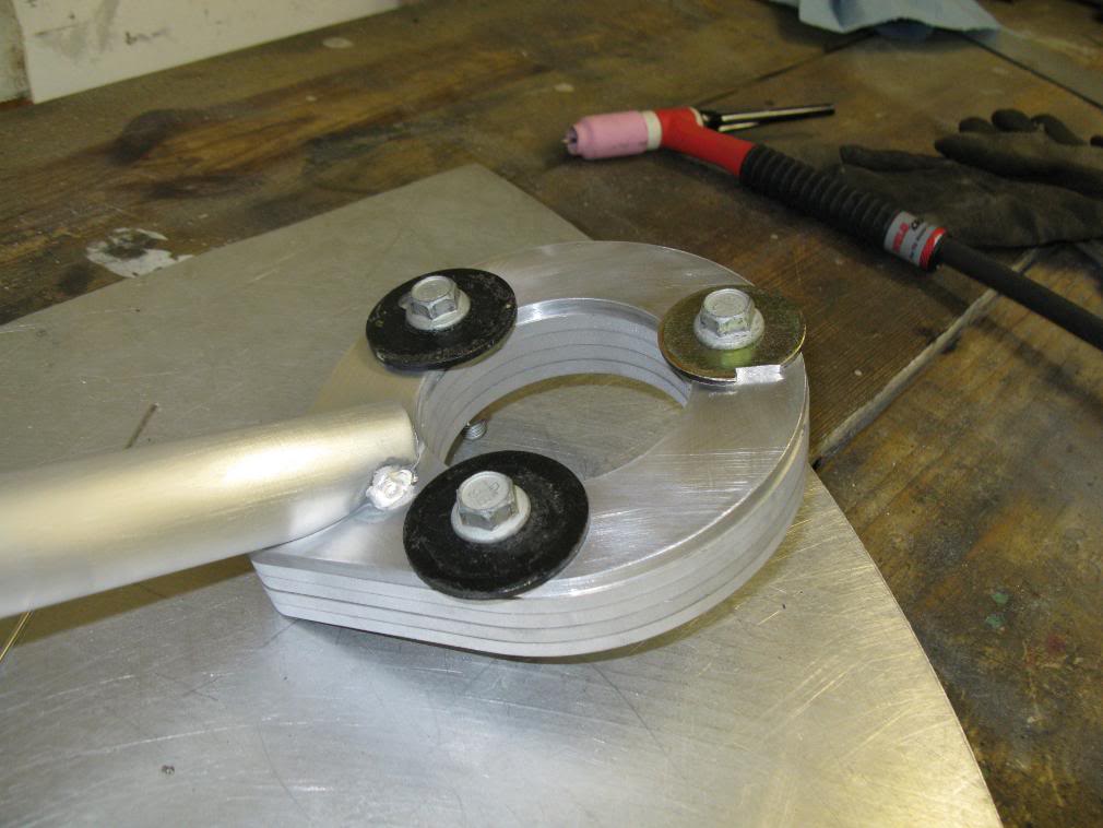
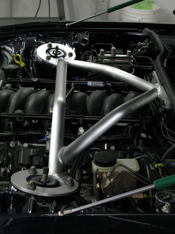
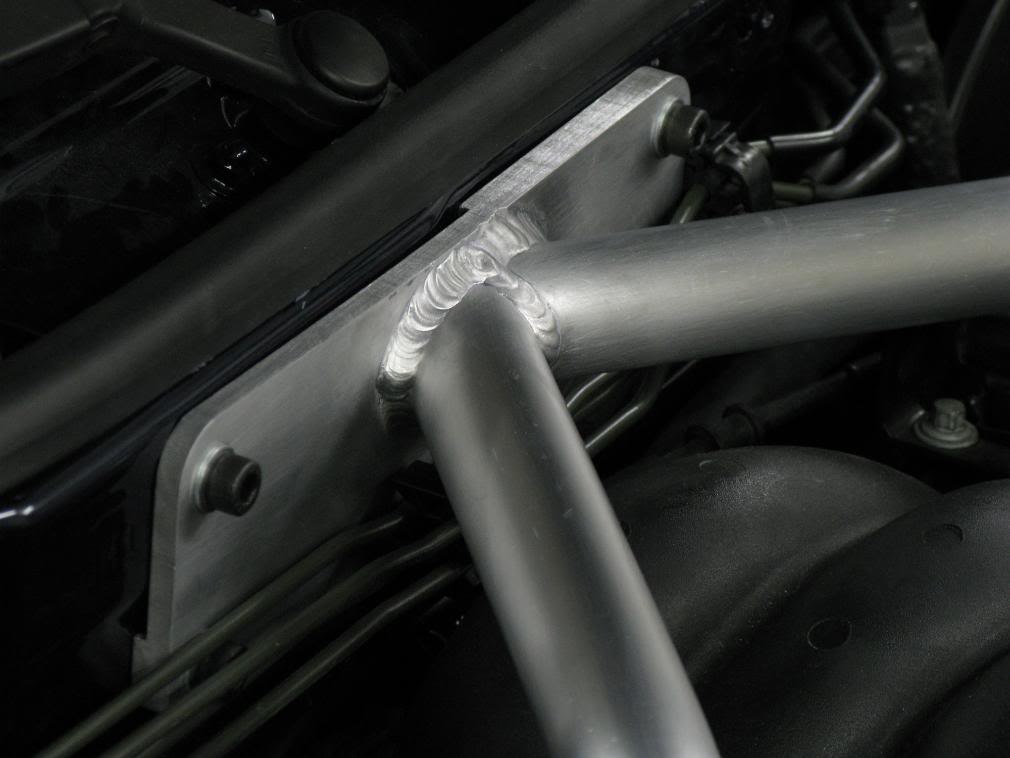
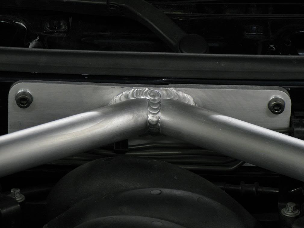
Got it all pretty much finished up today. The only thing left to do is get it coated if I decide to. I"m thinking annodized black, err something. Maybe powercoated satin black. I dunno.
Right now I just brushed it out with some scotch brite pads. Turned out pretty much fantastic.
The first two pics are of the measures I took to prevent flange warpage during welding. If I had not used those, the plates would have wanted to curl up.
Right now I just brushed it out with some scotch brite pads. Turned out pretty much fantastic.
The first two pics are of the measures I took to prevent flange warpage during welding. If I had not used those, the plates would have wanted to curl up.
 05-20-10, 10:12 AM
#37
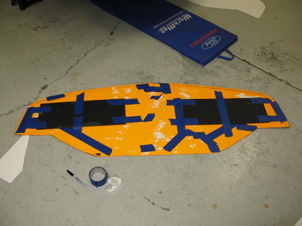
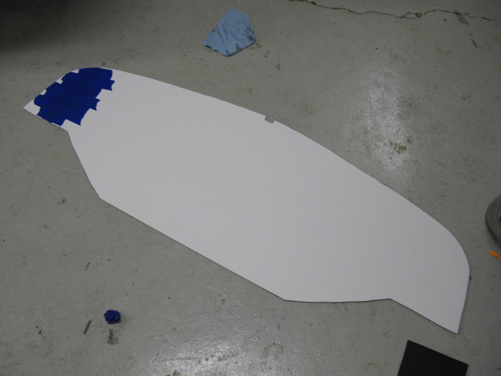
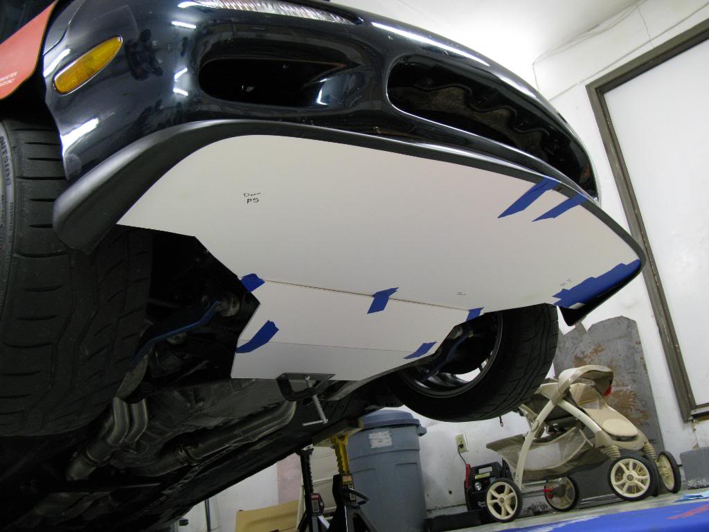
I started this little project for a few reasons. One reason was to improve the aerodynamics of the underbody of the car. The stock RX-7 came with a pretty similar undertray which I was unable to retain. The second reason was that I can easily attach a splitter to it for racing. The third reason was because I wanted to block off the volume surrounding the air filters. Right now I have the air filters right behind openings in the bumper covers where the stock oil coolers were located. I had nothing to cover the underside, so any high pressure air from the front of the car was lost under the car. With this undertray I'll be able to contain the air and hopefully pick up some manifold pressure at WOT (even if a few kPa I think it would help).
JuicedH22 Davey came over to help with some brainstorming, and to pick up the largest piece of foam board in the world. Getting that thing in the car was awesome, and it rested on Dave's head all the way home.
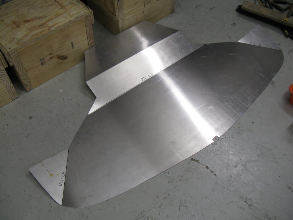
I am tucking the front edge of it up in the lip on the lip. I will probably attach it to the front of the lip with a few pop rivets to secure it in the front. On the back I'm thinking about using those sweet *** 1/4 turn racing things (can't remember the name for the life of me), and attaching it to the subframe. Mockup was started with poster board since its only $0.30 a sheet. Once I got the coutour of the front edge done I transfered over to the foam board. And kazam, all mocked up ready for some metal to be cut and bent. I'm going to be using aluminum, most likely.
JuicedH22 Davey came over to help with some brainstorming, and to pick up the largest piece of foam board in the world. Getting that thing in the car was awesome, and it rested on Dave's head all the way home.
I am tucking the front edge of it up in the lip on the lip. I will probably attach it to the front of the lip with a few pop rivets to secure it in the front. On the back I'm thinking about using those sweet *** 1/4 turn racing things (can't remember the name for the life of me), and attaching it to the subframe. Mockup was started with poster board since its only $0.30 a sheet. Once I got the coutour of the front edge done I transfered over to the foam board. And kazam, all mocked up ready for some metal to be cut and bent. I'm going to be using aluminum, most likely.
 05-20-10, 10:14 AM
#39
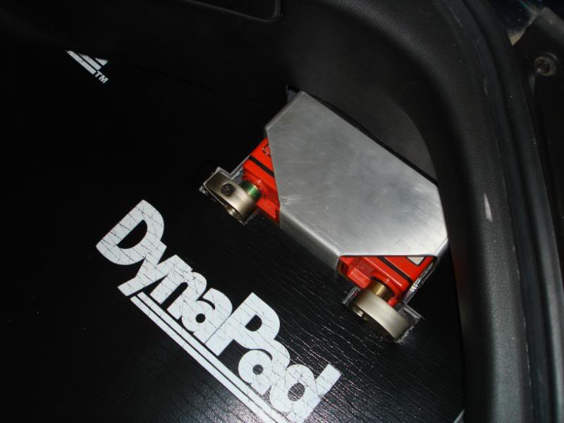
I previously had my battery mounted in my trunk, recessed in the plastic trim pannel. I had an Odyssey PC680MJT. Over the last two years I've realized that that battery was not all that great, especially after I raised the compression with a set of aftermarket heads. That said, I decided that a lightweight battery doesn't really have a place in a daily driven car.
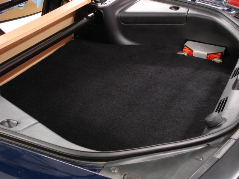
I bought an Optima battery, a 34/78 I think is the number. Its got 800 CCA, and 50 AH reserve, as compared to the Odyssey's 210 CCA, and 17 AH. The Optima was a full size battery, and would not fit where the small battery was. I needed to find somewhere else to mount it. There is a lot of flat space in the trunk, but the floorboard is pretty high in the trunk. I ended up deciding to put it in the passengers side plastic bin. Its about 12 or so inches lower than the trunk which is good, and its also in front of the axle, so closer to the center of the car by about 24"-30" which is also good.
I was able to remove a decent bit of weight, which helped offset the additional weight of the battery. I was able to get rid of 5 lbs of 1/0 cable, and cut the bottom of the bins out which saved ~4 lbs total. Added up with some misc. stuff, I pulled out ~8 lbs. The battery was 22 lbs heavier, so I ended up adding 14 lbs. But its lower, closer to the center and will make the car actually start reliably, so its definately worth the added weight to me.
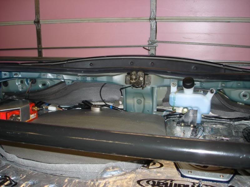
Here is where the battery was mounted.
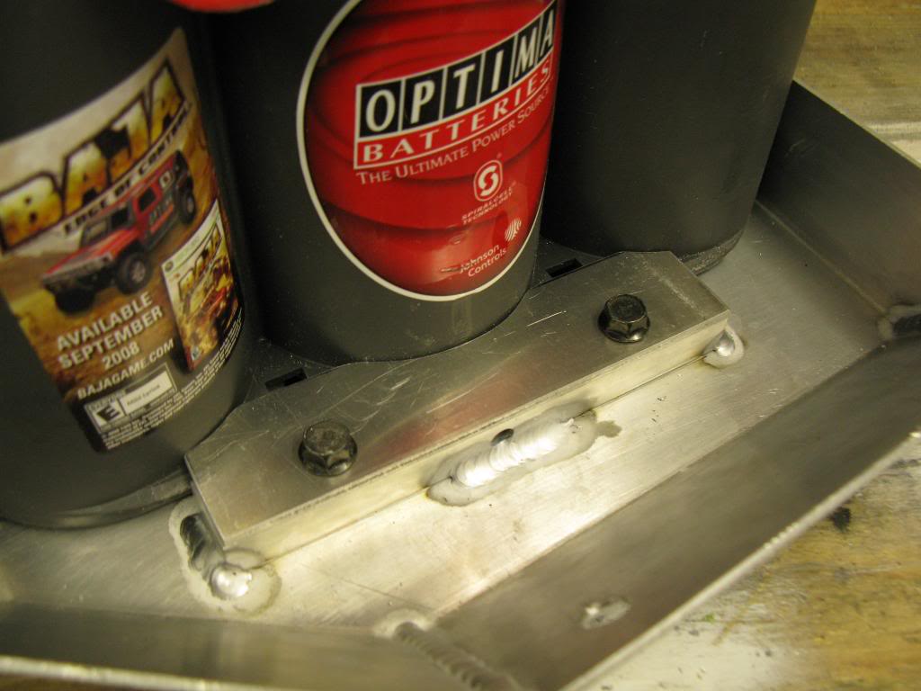
Here is the new Battery Tray/Bracket
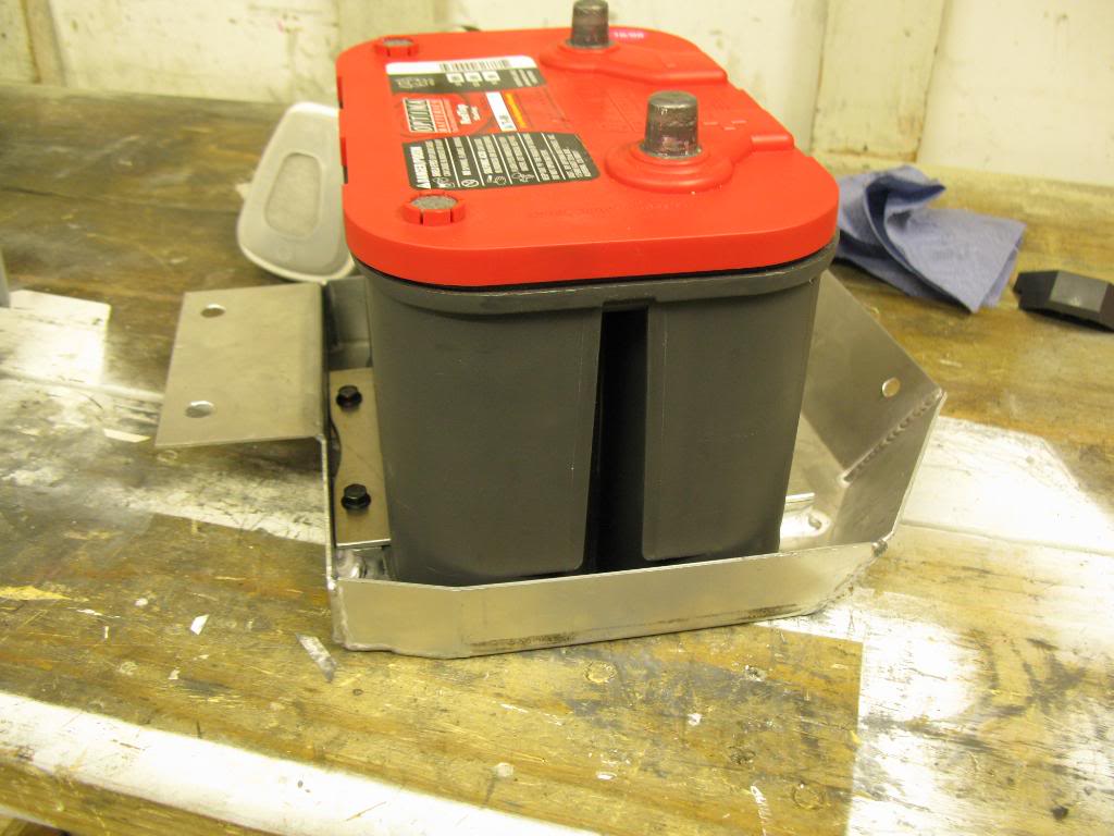
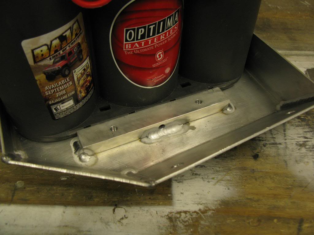
And the hold down closeups
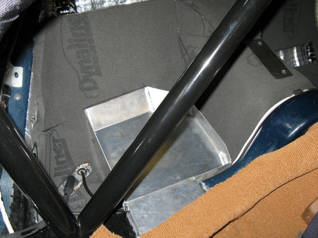
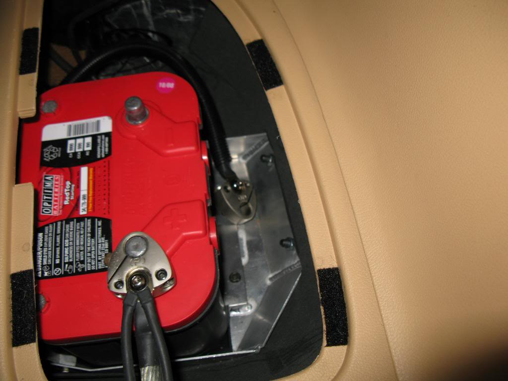
And all installed with wires routed. I'll put the lids on the bins, just left them off for pictures. When its all finished you won't even know its there.
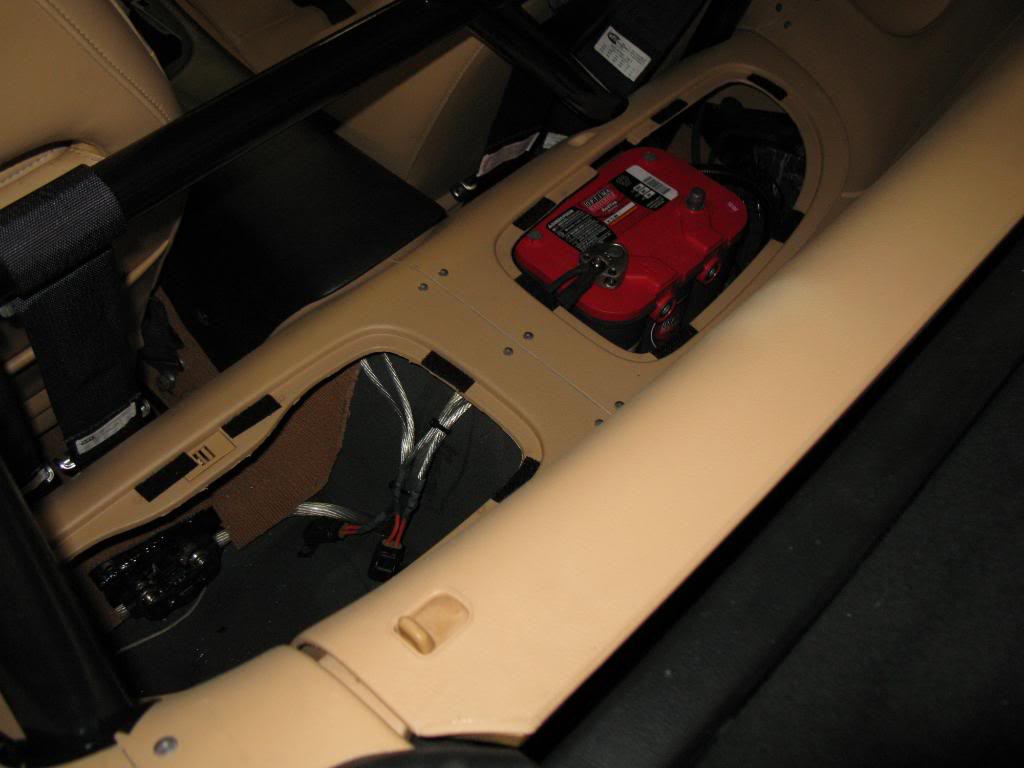
I bought an Optima battery, a 34/78 I think is the number. Its got 800 CCA, and 50 AH reserve, as compared to the Odyssey's 210 CCA, and 17 AH. The Optima was a full size battery, and would not fit where the small battery was. I needed to find somewhere else to mount it. There is a lot of flat space in the trunk, but the floorboard is pretty high in the trunk. I ended up deciding to put it in the passengers side plastic bin. Its about 12 or so inches lower than the trunk which is good, and its also in front of the axle, so closer to the center of the car by about 24"-30" which is also good.
I was able to remove a decent bit of weight, which helped offset the additional weight of the battery. I was able to get rid of 5 lbs of 1/0 cable, and cut the bottom of the bins out which saved ~4 lbs total. Added up with some misc. stuff, I pulled out ~8 lbs. The battery was 22 lbs heavier, so I ended up adding 14 lbs. But its lower, closer to the center and will make the car actually start reliably, so its definately worth the added weight to me.
Here is where the battery was mounted.
Here is the new Battery Tray/Bracket
And the hold down closeups
And all installed with wires routed. I'll put the lids on the bins, just left them off for pictures. When its all finished you won't even know its there.
05-20-10, 10:16 AM
#40
Took a day off work today and did a bit of dyno tuning. Didn't make any huge changes really, but they made a decent bit more torque than the baseline tune I came in with. Dave Blundell helped me a bit with the tune and some suggestions, and operated the dyno. I did it at TPR on the dynapacks, in 4th gear.
All in all, I'm a happy camper!
487 hp - 435 ft-lbs
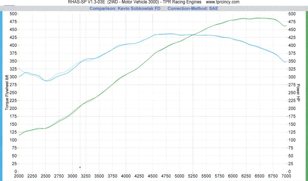
All in all, I'm a happy camper!
487 hp - 435 ft-lbs
05-20-10, 10:18 AM
#41
This a bit out of order here, but oh well....
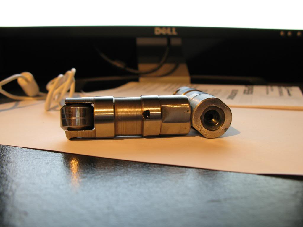
The idea here it to cut reliefs into the piston to obtain adaquate piston to valve (PTV) clearance.
The tools used were purchased from Lindy Tool Company. The tool installs into the valve guide just as a valve would. Instead of a valve head, there is a cutting head. You set the cut depth, attach a drill and cut till it hits the depth stop collar. I will have in depth explanation on all of this with pictures as I progress.
To be on the safe side, I obtained a scrap head (thanks BES_Stroked_Nova). This prevents me from damaging the valve guides in my good set of heads. The heads I'm installing are PRC Stg. 2.5 5.3l heads, GM casting number XXX. The sprap head casting number is a GM 706, which is alos a 5.3l head. To be sure the heads would serve as an appropiate guide I measured valve angle, and a few other things.
Now, my good PRC heads have been milled down to a 59cc combustion chamber, and the junk heads are of unknown milling status. To maintain proper geometry, I need the centerline axis of the valve to be co-linear between the heads. Here is how I have done so.
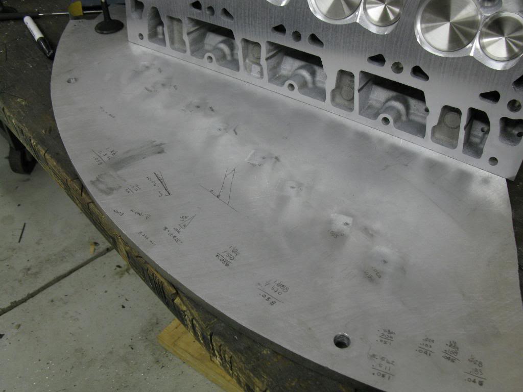
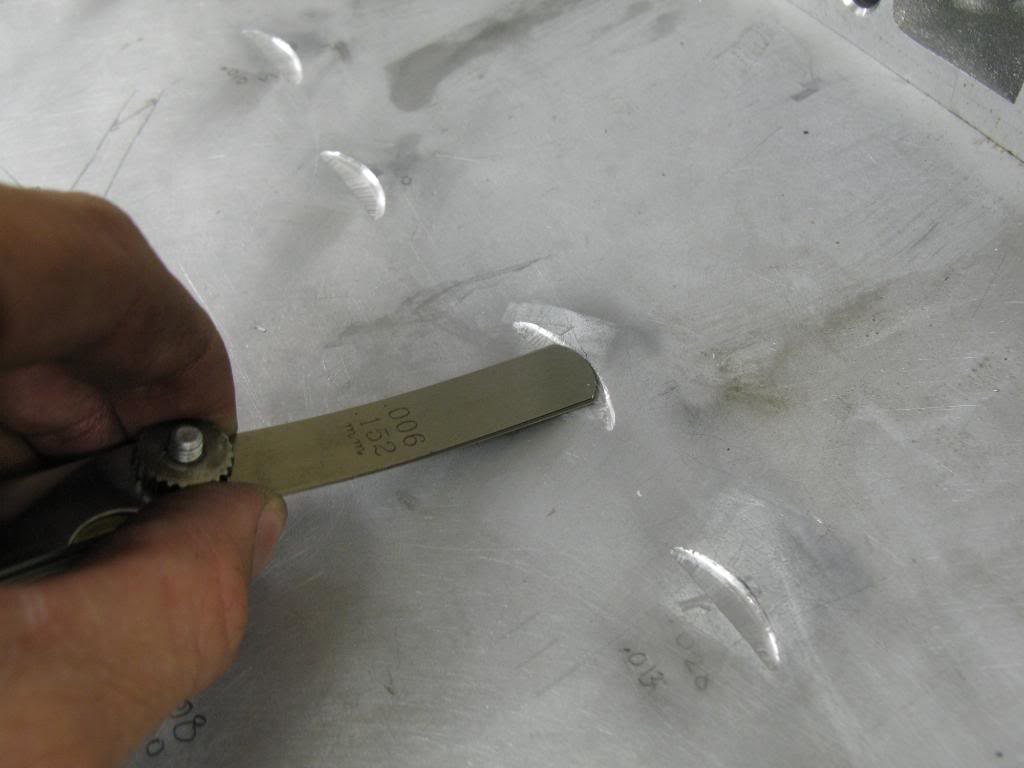
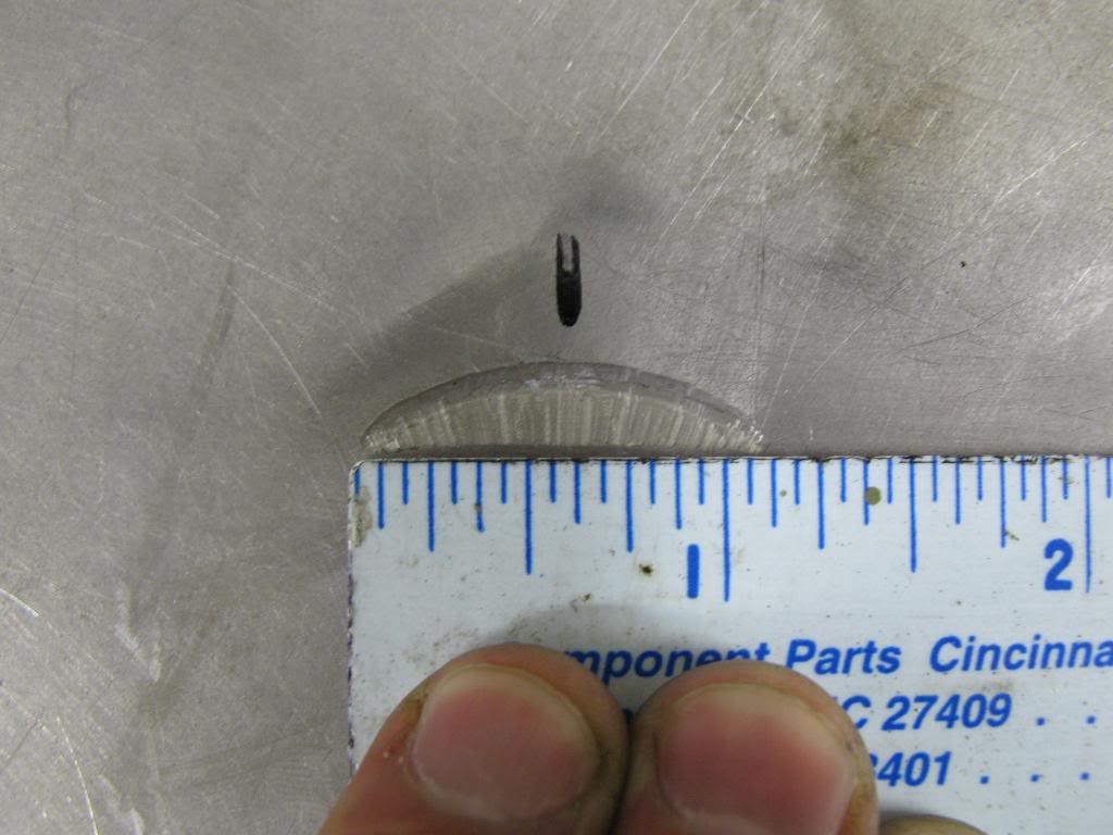
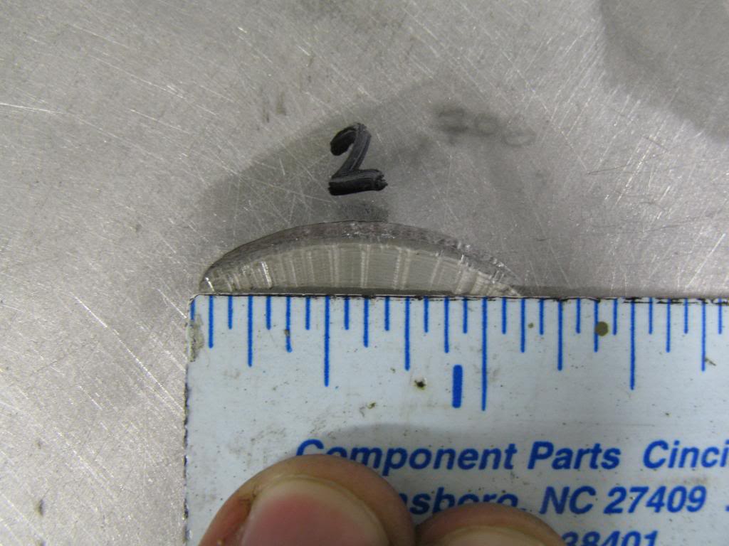
I made a fixture to hold both heads (the good one and the junk one) in the same location in respect to the alignment dowels. I installed the junk head with the new valves onto the fixture. When doing this procedure you must use the same set of valves on both heads. Then I pushed on the valve until it hit the aluminum plate. I spun the valve by hand, sort of grinding the edge of the valve into the aluminum. This made score in the aluminum. I did that for alll 8 valves. Then I put on the good head on did the same thing. If the centerline of the valve guides were co-linear then the marks would be in the same exact spot. As suspected, they were not in the same location.
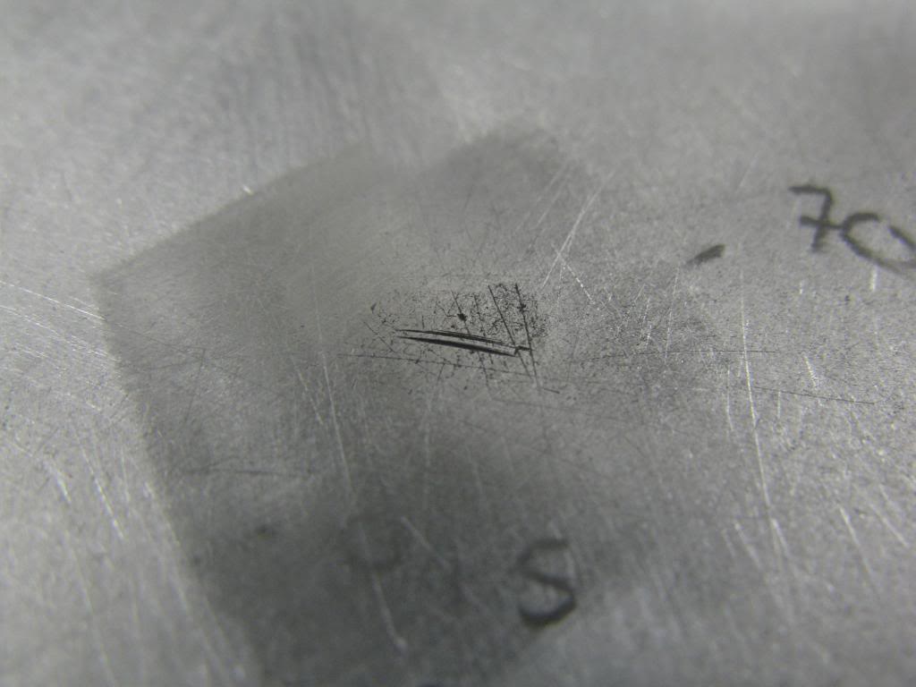
To have accurately located flycuts in the piston I need the valves in the both heads to contact in the same spot. Now I must determine how much needs to be milled off of the junk head. To do this I employed two techniques, and used them as a reality check to make sure they both agree.
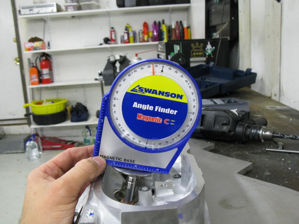
1. First I measured the distance between the two marks for each valve. Then I averaged them. I came up with an average of 0.0102" for all 8 valves. Then I measured the vavle angle to be 14 degrees. Knowing the distance between the two marks, and the valve angle I can determine the amount to be milled off of the junk head using some trig. I came up with 0.0409" to be milled off the junk head.
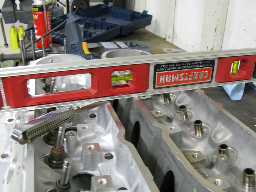
2. Second measurement was to put both heads on a flat surface, and put a straight edge across the top both heads. Using feeler gauges I measured the difference to be 0.037".
The two types of measurement differ by only ~0.003" so I'm satisfied that its correct. The more I think about it, the more I wonder how much different the answer would be if my measurement was off by 0.001" or 0.002", or my valve angle measurement was off by +/- 1 degree. If my measurement was off by 0.002 I could have an answer of 0.034". If I was off by angle, it could be 0.0388". Those very closely agree with my measured 0.037 height difference. Because of that I think I will mill off 0.035"
I will mill 0.035" becasue more milling would provide more clearance because only that side of the valve would contact the piston. In addition, the cutters have a 0.040" radial clearance for the valve. After i mill the head, I will reattach it to the fixture and make a new set of marks. The marks should be in the exact same spot as the PRC heads. If this is the case, I will proceed to the next step. I'll keep this thread updated as I go.
The idea here it to cut reliefs into the piston to obtain adaquate piston to valve (PTV) clearance.
The tools used were purchased from Lindy Tool Company. The tool installs into the valve guide just as a valve would. Instead of a valve head, there is a cutting head. You set the cut depth, attach a drill and cut till it hits the depth stop collar. I will have in depth explanation on all of this with pictures as I progress.
To be on the safe side, I obtained a scrap head (thanks BES_Stroked_Nova). This prevents me from damaging the valve guides in my good set of heads. The heads I'm installing are PRC Stg. 2.5 5.3l heads, GM casting number XXX. The sprap head casting number is a GM 706, which is alos a 5.3l head. To be sure the heads would serve as an appropiate guide I measured valve angle, and a few other things.
Now, my good PRC heads have been milled down to a 59cc combustion chamber, and the junk heads are of unknown milling status. To maintain proper geometry, I need the centerline axis of the valve to be co-linear between the heads. Here is how I have done so.
I made a fixture to hold both heads (the good one and the junk one) in the same location in respect to the alignment dowels. I installed the junk head with the new valves onto the fixture. When doing this procedure you must use the same set of valves on both heads. Then I pushed on the valve until it hit the aluminum plate. I spun the valve by hand, sort of grinding the edge of the valve into the aluminum. This made score in the aluminum. I did that for alll 8 valves. Then I put on the good head on did the same thing. If the centerline of the valve guides were co-linear then the marks would be in the same exact spot. As suspected, they were not in the same location.
To have accurately located flycuts in the piston I need the valves in the both heads to contact in the same spot. Now I must determine how much needs to be milled off of the junk head. To do this I employed two techniques, and used them as a reality check to make sure they both agree.
1. First I measured the distance between the two marks for each valve. Then I averaged them. I came up with an average of 0.0102" for all 8 valves. Then I measured the vavle angle to be 14 degrees. Knowing the distance between the two marks, and the valve angle I can determine the amount to be milled off of the junk head using some trig. I came up with 0.0409" to be milled off the junk head.
2. Second measurement was to put both heads on a flat surface, and put a straight edge across the top both heads. Using feeler gauges I measured the difference to be 0.037".
The two types of measurement differ by only ~0.003" so I'm satisfied that its correct. The more I think about it, the more I wonder how much different the answer would be if my measurement was off by 0.001" or 0.002", or my valve angle measurement was off by +/- 1 degree. If my measurement was off by 0.002 I could have an answer of 0.034". If I was off by angle, it could be 0.0388". Those very closely agree with my measured 0.037 height difference. Because of that I think I will mill off 0.035"
I will mill 0.035" becasue more milling would provide more clearance because only that side of the valve would contact the piston. In addition, the cutters have a 0.040" radial clearance for the valve. After i mill the head, I will reattach it to the fixture and make a new set of marks. The marks should be in the exact same spot as the PRC heads. If this is the case, I will proceed to the next step. I'll keep this thread updated as I go.
05-20-10, 10:19 AM
#42
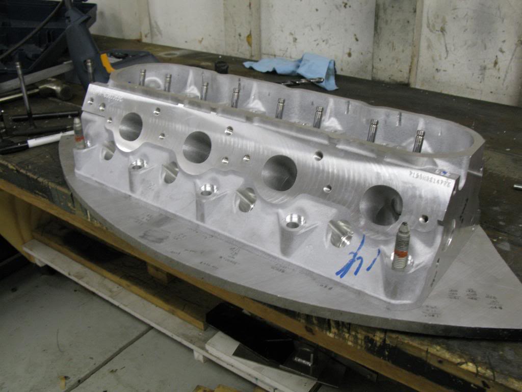
After a much awaited arival (damn UPS theives) my second set of heads finally arrived. They are from Texas Speed, aka Precision Race Components (PRC). They are their stage 2.5 CNC ported 5.3 liter heads.
Intake flow data:
.300 208
.400 257
.500 290
.600 312
They sure are pretty.
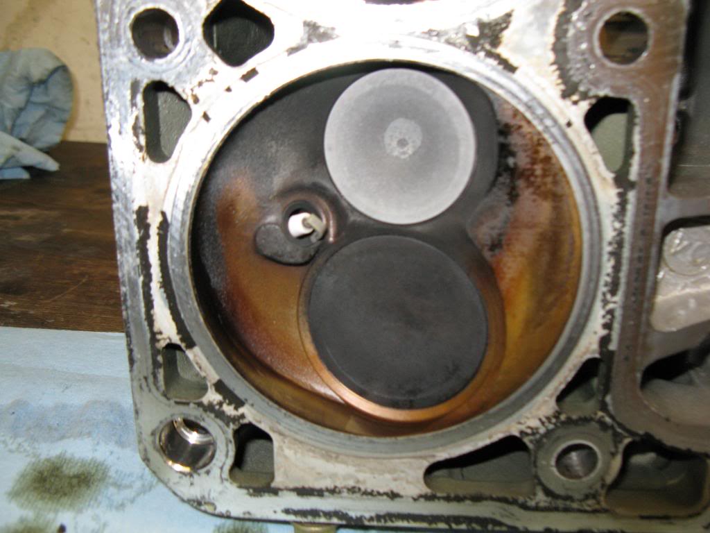
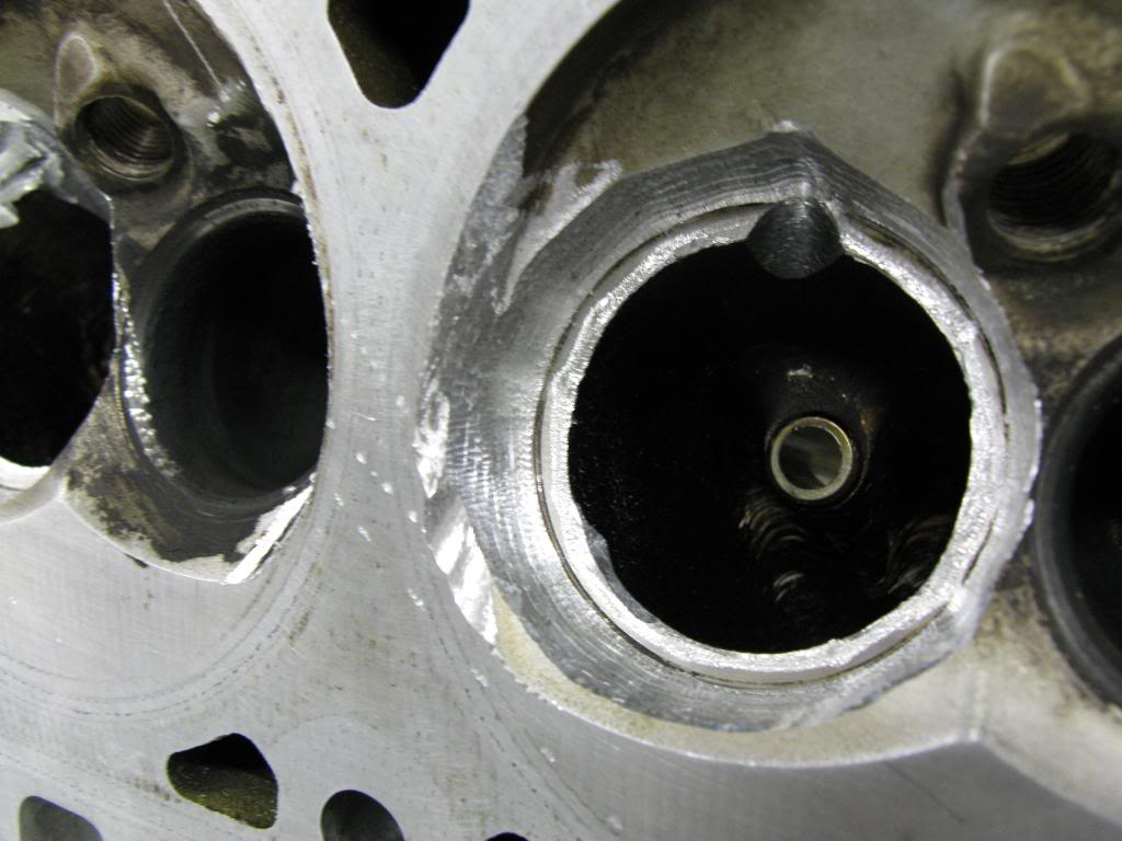
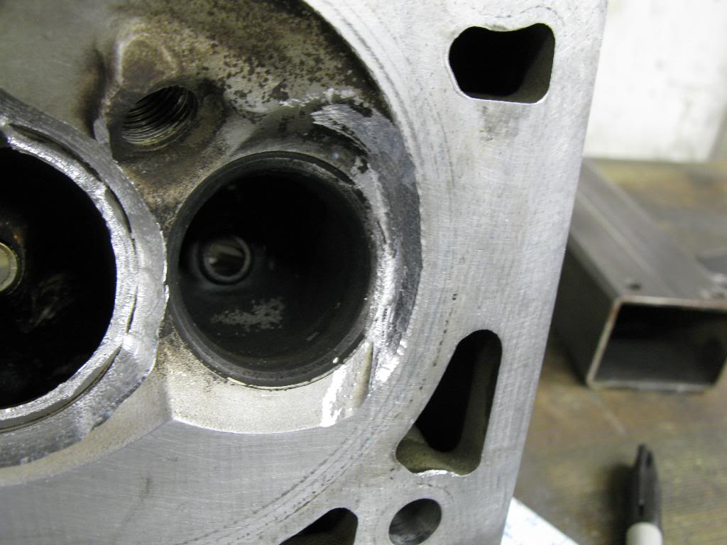
Combustion Chamber
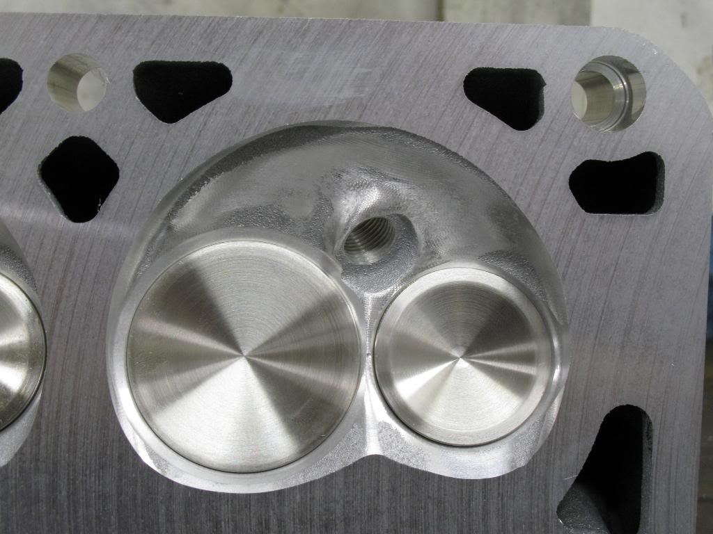
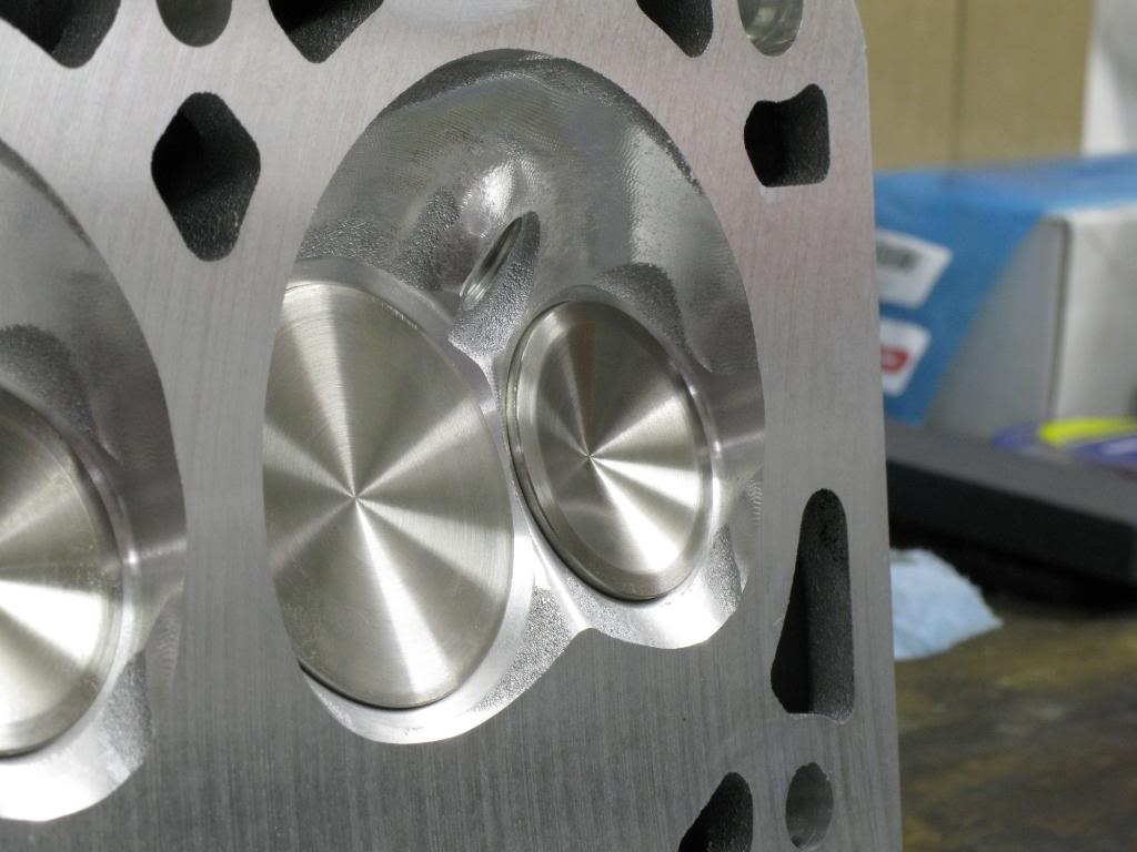
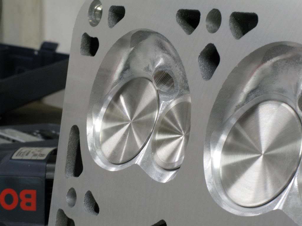
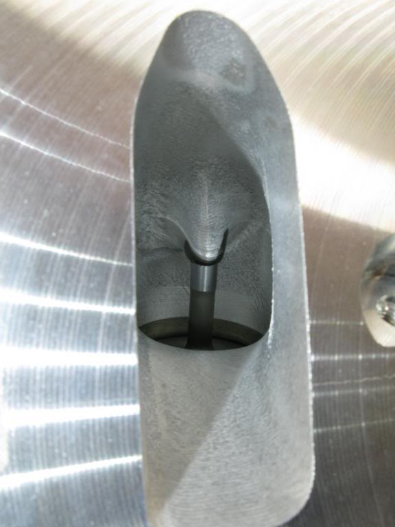
Looking in the intake port form the valve side
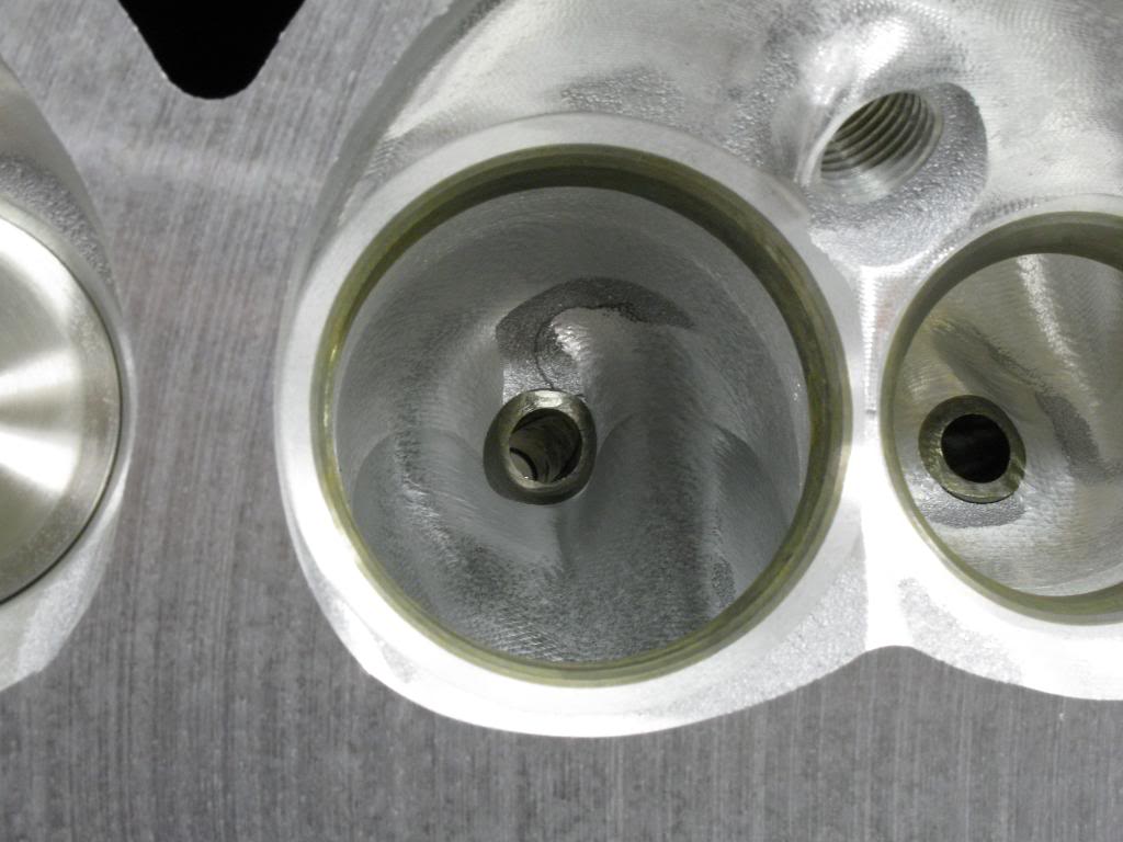
Looking in the exhasut port from the valve side.
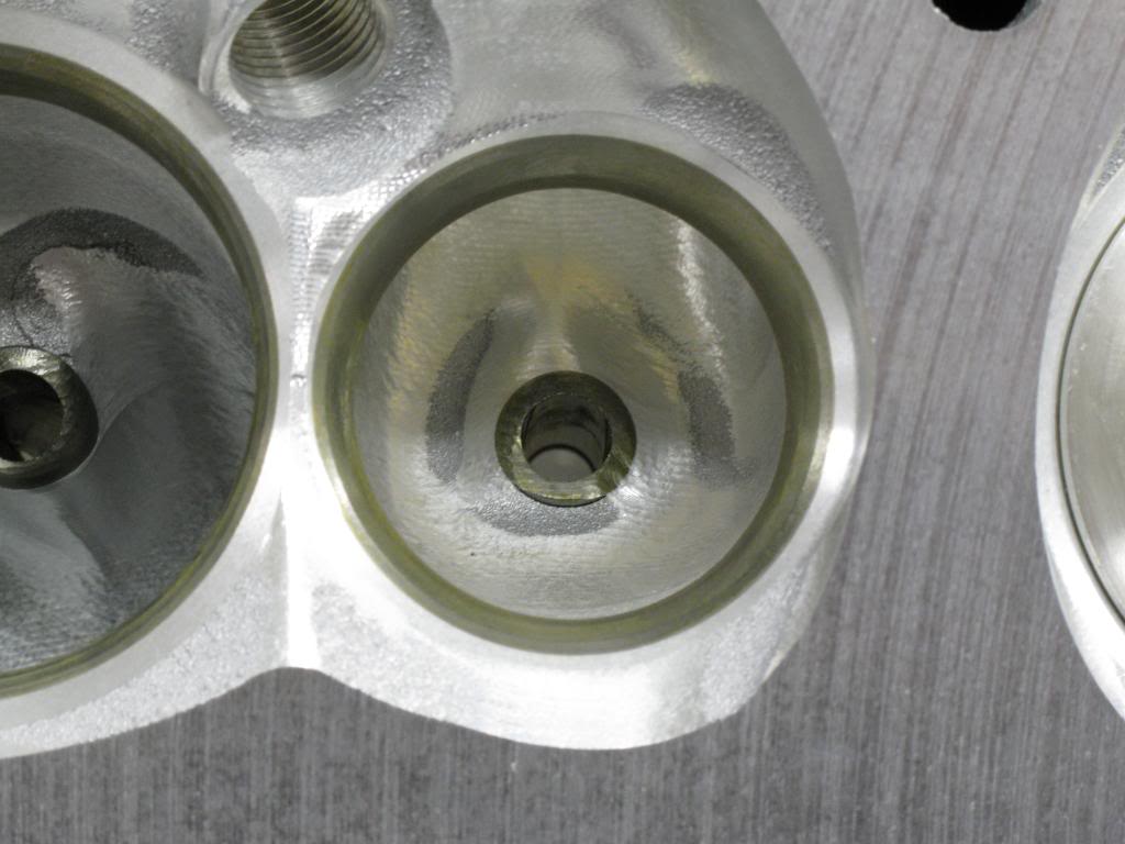
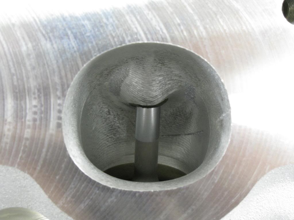
Looking in the intake port from the intake side.
Looking in the exhaust port from the exhaust side.
Intake flow data:
.300 208
.400 257
.500 290
.600 312
They sure are pretty.
Combustion Chamber
Looking in the intake port form the valve side
Looking in the exhasut port from the valve side.
Looking in the intake port from the intake side.
Looking in the exhaust port from the exhaust side.
05-20-10, 10:24 AM
#43
Ok, scratch milling the junk head. I just got off the phone with Jason at Texas Speed. He said they mill 0.040 off the heads to get a 59cc chamber. So my measuring technique was pretty much right on. But, he did say that he does things a bit different. He uses an unmilled head, and no head gasket. On LS1s the piston comes out of the bore slightly. He suggested bolting the unmilled head on the block, and then rotating the piston around till it pushes up against the head. This will keep the piston in a positive position, and you don't need to worry about getting TDC, since ti will automatically be pretty much there. This will also keep the piston preloaded, and prevent it from rocking and chattering when cutting the reliefs. I think I'll use that method instead.
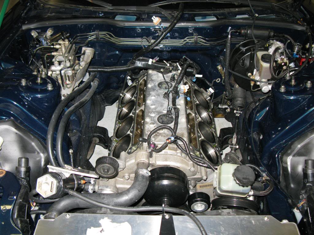
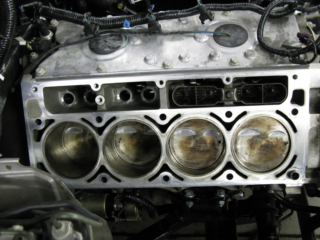
Well I finally decided to get to work installing these things. I removed the stock heads and I was pleasantly sprprised how clean everything was. Looks like I had it running pretty good afterall. There isn't any carbon buildup anywhere. The valves look greyish/white, as well as the header primaries. Not real sure why they're that color. Looks almost as if I was running race gas, but that is not the case. The spark plugs even looked nearly brand new. The heads are infinately easier than removing the head on my late 4G63 engine. Cylinder walls still look like new, crosshatch and all. Although with 18k miles I'd expect nothing less.

After I removed the heads I thought I'd save some money and swap the springs over myself instead of taking it to a machine shop. I made it out of a few thinsg laying around. Worked like a charm and was quick and easy to do. Little bit of DIY action in full force.
Then I made a bolt to clean out all the factory thread locker that is all up in the head bolt holes. I just chucked the bolt in my drill press and milled down the side. Works pretty good. Cleans them right up real quick.
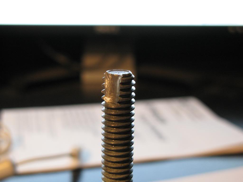
Well I finally decided to get to work installing these things. I removed the stock heads and I was pleasantly sprprised how clean everything was. Looks like I had it running pretty good afterall. There isn't any carbon buildup anywhere. The valves look greyish/white, as well as the header primaries. Not real sure why they're that color. Looks almost as if I was running race gas, but that is not the case. The spark plugs even looked nearly brand new. The heads are infinately easier than removing the head on my late 4G63 engine. Cylinder walls still look like new, crosshatch and all. Although with 18k miles I'd expect nothing less.
After I removed the heads I thought I'd save some money and swap the springs over myself instead of taking it to a machine shop. I made it out of a few thinsg laying around. Worked like a charm and was quick and easy to do. Little bit of DIY action in full force.
Then I made a bolt to clean out all the factory thread locker that is all up in the head bolt holes. I just chucked the bolt in my drill press and milled down the side. Works pretty good. Cleans them right up real quick.
05-20-10, 10:24 AM
#44
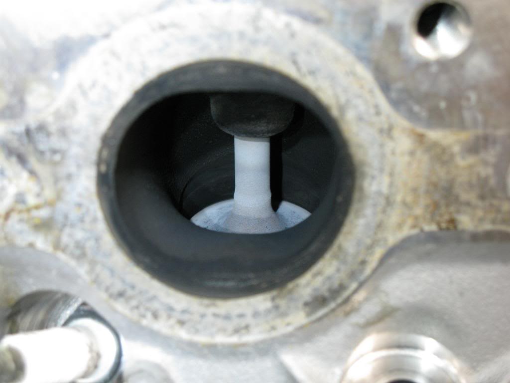
I started fooling wiht the flycutting a bit today. I test fit the cutters into the head and realized they dind't fit, so I had to do a bit of "deshrouding" with my carbide grinder to make them fit. Then I also realized that the intake cutter protruded past the surface of the head, so that wasn't gonna work. I cut out the valve seat and gringed the **** out of that area to make it fit. So much for using the Lindy tool on a good head. There may have been a better, or different way to amke it work but I didn't care since the head is junk anyhow.
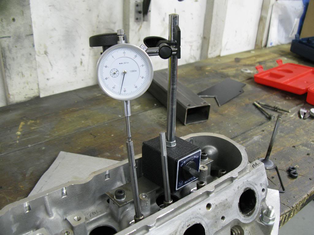
I had to make a ferrous plate to bolt in the head so my magnetic base dial gauge could stick to something.
Then I installed the cutter, and used the dial gauge to determine the highest point on the cutter. Once I have the cutter at its highest point I can set the cutter depth. I used a tip form another forum member. Once the cutter was at its highest point I slid a collar down and snugged it. Then I slid another collar on. I put a stack of feeler gauges, 0.040" worth, between the collars. Then I tightened the **** out of the top collar. Then I removed the feeler gauges. Then I loosened the bottom collar so it would be snug, but still allow me to plunge the cutter down. This effectively limited my feed rate, and controlled the cutter better.
Then I made 4 practice cuts. I wanted to make sure I could consistantly cut the reliefs to a depth, and the depth that it cut was the depth I set. After I made the cuts I would check the depth with the feeler gauges. Another way to check is to measure the length of the cut. A small difference in depth would show up as a difference in cut width. I used both methods to make sure the cuts were consistant.
05-20-10, 10:27 AM
#45
Well since I didn't really want to cut vavle reliefs in my pistons high on prescription meds I figured I'd so something less risky (herniated disc pressing against my spinal cord). I started looking at port matching my LS6 intake manifold to the heads. I bolted them on, looked through the combustion chamber with a mirror to see how much material had to be removed from the manifold. It was approximately 1/16" all around. There was also a squared off edge near the injector boss. I decided to round that off to help prevent some turbulance.
Manifold all marked with white paint marker, and line scribed in to mark where I was going to port to.
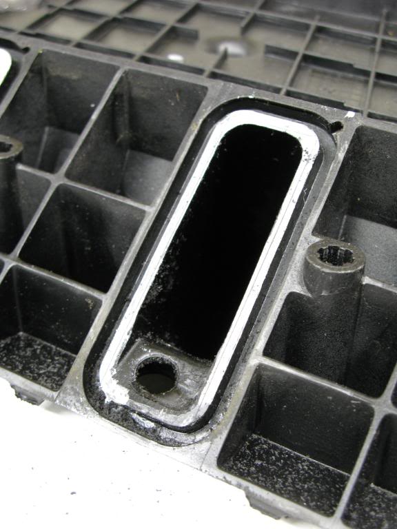
Squarted off edge I wanted to round.
All ported up and rounded.
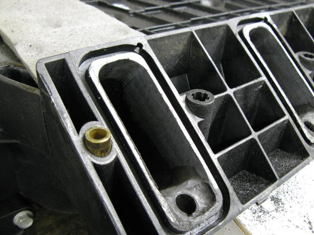
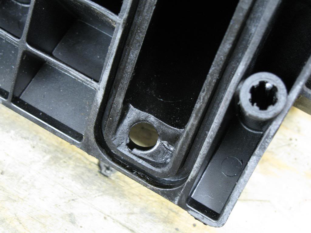
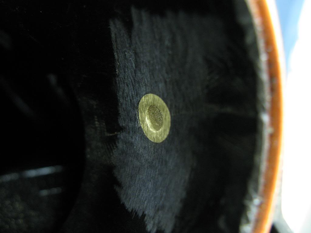
At the inlet of the manifold there was this brass fitting protruding slightly. There was also a raised circle in the casting.
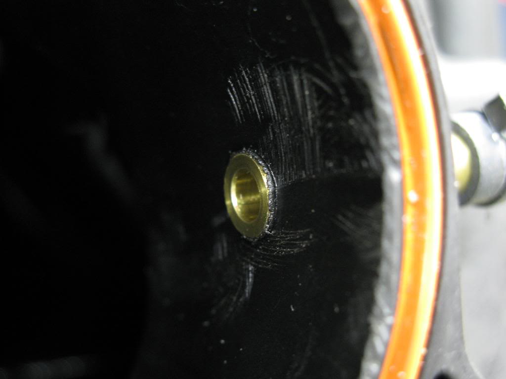
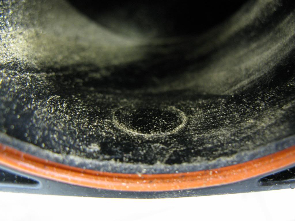
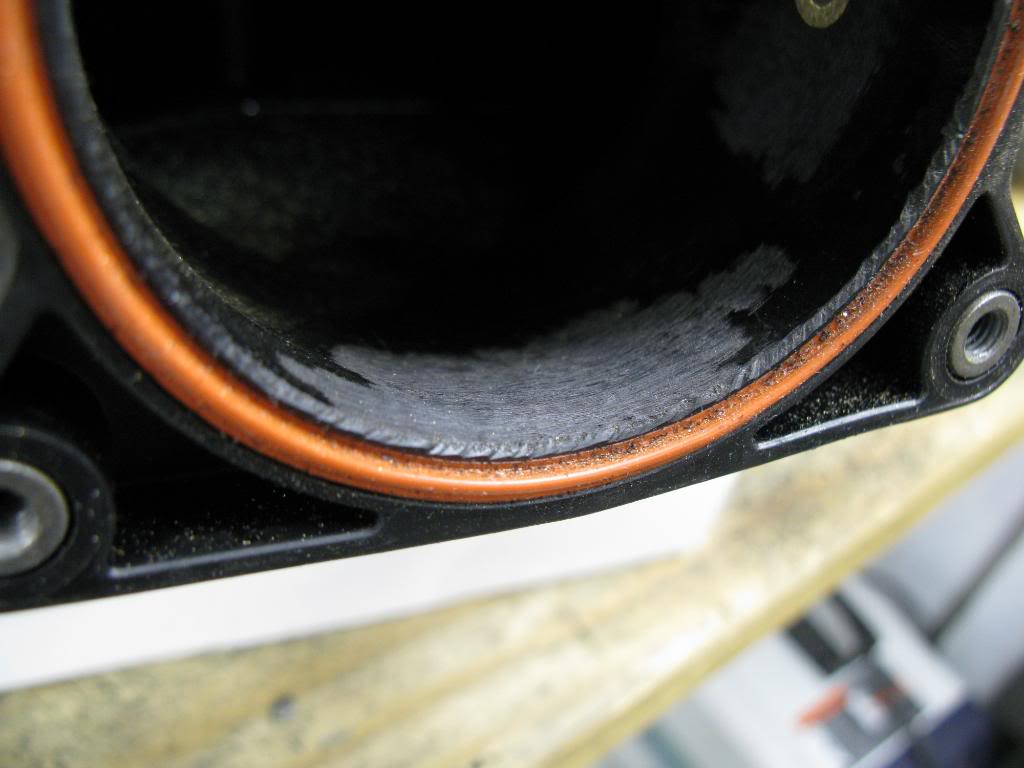
And removed.
I think I just gained like 0.5 hp! LOL.
Manifold all marked with white paint marker, and line scribed in to mark where I was going to port to.
Squarted off edge I wanted to round.
All ported up and rounded.
At the inlet of the manifold there was this brass fitting protruding slightly. There was also a raised circle in the casting.
And removed.
I think I just gained like 0.5 hp! LOL.
05-20-10, 10:30 AM
#46
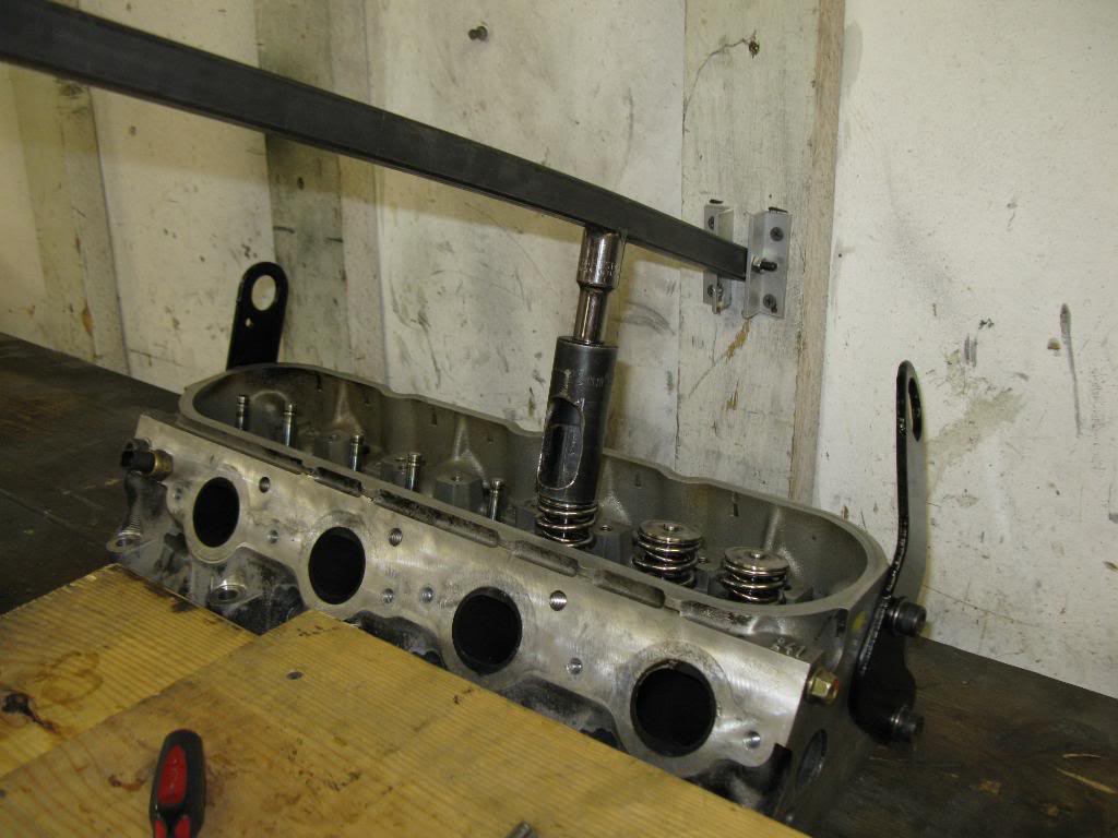
Borrowed Ray's vavle spring compressor to take put the springs back on. It took a lot of force to get these bad boys on. I nearly herniated another disc in my back. They're rated at 2.000" lift, but they only can take 4 rpms.

I got these two springs from Home Depot in the screen door area. Work perfectly as check springs. I had to cut them down a bit to get as little spring pressure as possible, yet still hold the valves up.
I got these two springs from Home Depot in the screen door area. Work perfectly as check springs. I had to cut them down a bit to get as little spring pressure as possible, yet still hold the valves up.
05-20-10, 10:31 AM
#47
I made some more practice cuts on the aluminum plate. I used an air drill and the results were much better. Significanly less chatter, and no chatter on a few cuts.
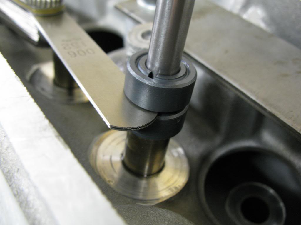
I checked the piston to valve clearance on the intake valve w/o any reliefs. 0.025". I have yet to check the exhasut PTVC, I'll do that one tomorrow.
Here was the setup I used.
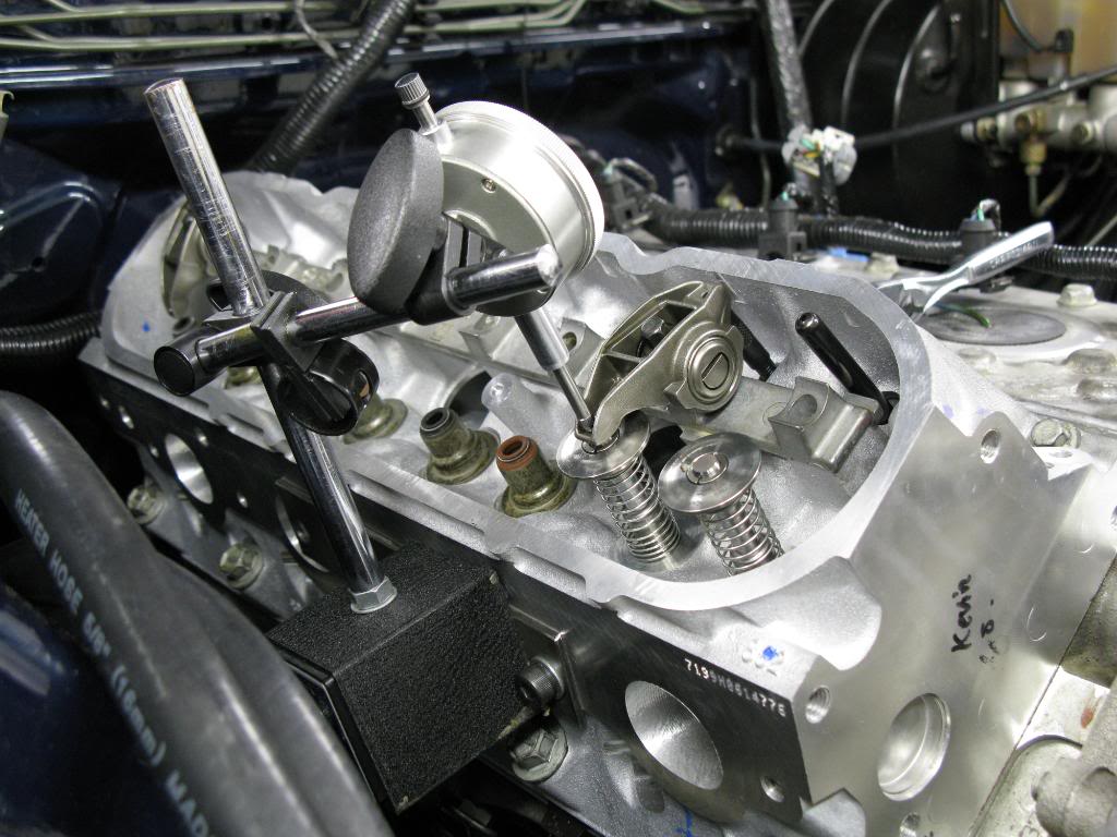
I have the MS4 cam on a stock bottom end LS1. LS7 lifters, GM MLS headgasket, PRC 2.5 5.3l heads with 59cc chambers (milled 0.040"). I'm shooting for 0.080" PTVC, so I suppose I'll make my intake cuts 0.060" deep. That should give me an 0.085" PTVC on the intake. I suppose that gives me an allotment of 0.005" for measurement error.
I checked the piston to valve clearance on the intake valve w/o any reliefs. 0.025". I have yet to check the exhasut PTVC, I'll do that one tomorrow.
Here was the setup I used.
I have the MS4 cam on a stock bottom end LS1. LS7 lifters, GM MLS headgasket, PRC 2.5 5.3l heads with 59cc chambers (milled 0.040"). I'm shooting for 0.080" PTVC, so I suppose I'll make my intake cuts 0.060" deep. That should give me an 0.085" PTVC on the intake. I suppose that gives me an allotment of 0.005" for measurement error.
05-20-10, 10:34 AM
#48
So since I'm a novice I messed up the measurement on the PTVC. I was rotating the motor CCW when I was checking, and not CW. I also did not have all the lash adjusted out of the pushrods with the length checker. All those things fixed I measured:
0.004" clearance on the intake valve.
0.000" clearance on the exhaust valve. Aka, contact.
I was unsatisified that my method of checking PTV clearance was adaquate using the hydraulic lifters (even with the light check spring), so I just modified two stock lifters. I welded the lifters up solid. New PTVC numbers tomorrow....
I put the modified solid lifters in today and remeasured the clearances. I came up with 0.003" intake, and 0.001" exhaust. Then I realized I made a mistake when I was removing the exhaust rocker. I used the same length pushrod (on the adjustable checker) for both intake and exhaust measurements. I then double checked the PR lengths required. The exhaust pushrod needed to be 3/4 of a turn shorter than the intake pushrod, which equates to ~0.0375" difference. That meant that when I measured the clearance on the exhaust valve the valve was 0.037 more closed than it should have been.
So I rechecked, each clearance, making sure to have zero lash and the appropiate pushrod length for each.
I remeasured and got these numbers. The new exhaust number reflects exactly the difference in pushrod length.
Intake: 0.003"
Exhaust: 0.038"
I know if you read through this thread you'll see that I measured about 58 times, and came up with a different result each time. I feel pretty confident that I measured correctly this time. I checked with the dial indicator, and then also with feeler gauges between the valve tip and rocker. Another thing worth noting when measuring is that the tightest intake clearance it occurs as the cam is ramping up in its profile, while the tightest exhaust clearance occurs when the cam is ramping down. Because of that, you have to ensure the lifter is seated up against the cam, and not sticking in the lifter trays. With only a test spring on the valve, it could stick and you would not know. Each time I'd measure I'd push down on the rocker to amke sure the lifter was up against the cam.
Given my results to maintain 0.080" clearance on the intake side, and 0.100" clearance on the exhaust side I would have to cut:
Intake cut: 0.077"
Exhaust cut: 0.062"
Given that I may end up cutting 0.080" on the intake, and 0.065" on the exhaust side.
I think I may actually cut today, or maybe tomorrow.
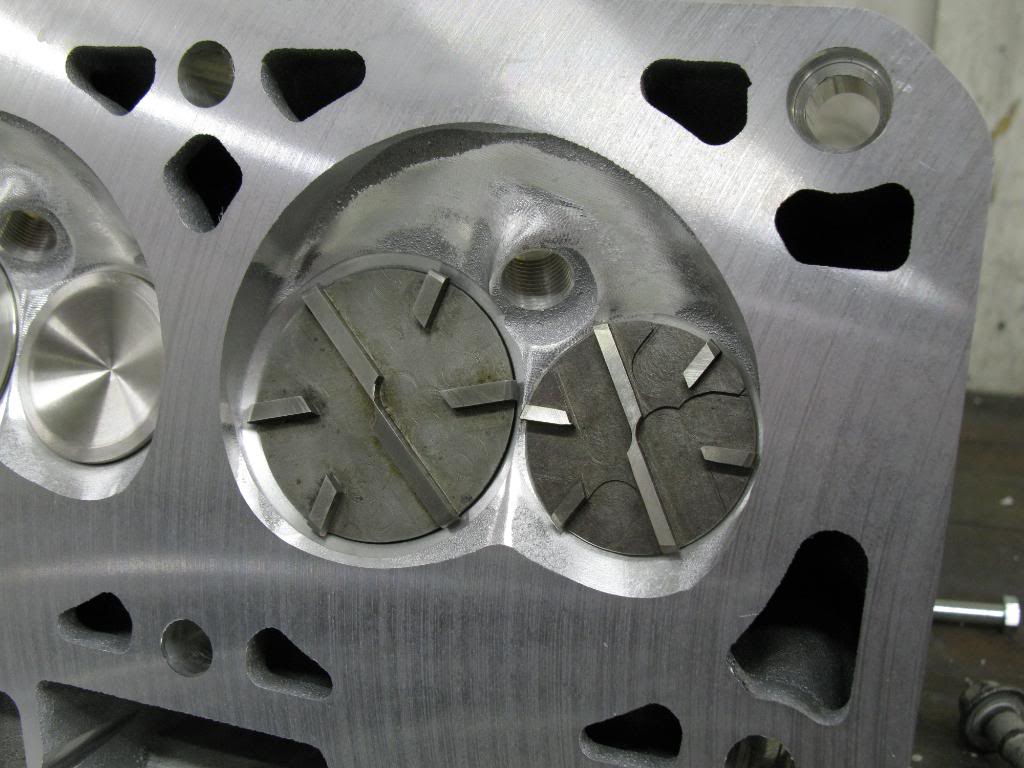
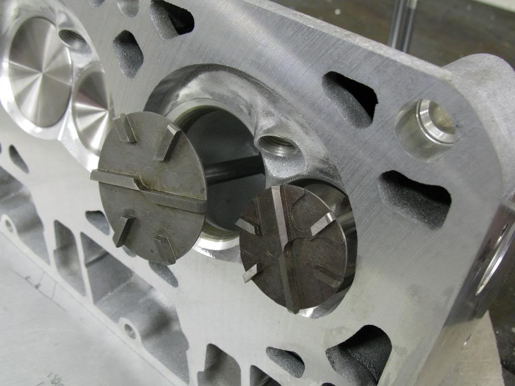
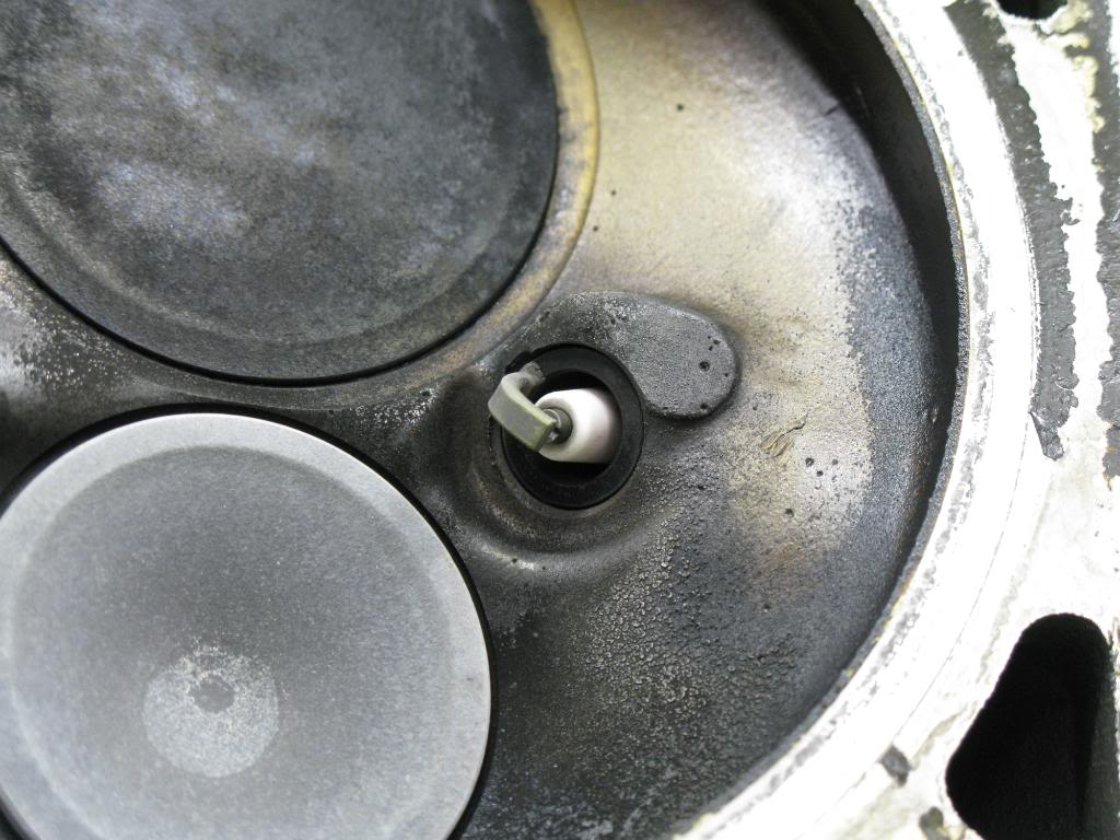
So I finally made my first cuts. I cut 0.080" on the intake, and 0.065" on the exhaust. That should have given me 0.083" PTVC and 0.103" PTVC respectively. After I made the cuts I measured and came up wiht 0.080" PTVC, and 0.097" PTVC. Looks like there is some spring in the material as it cuts or something. Close enough for government work.
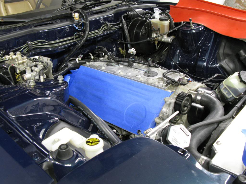
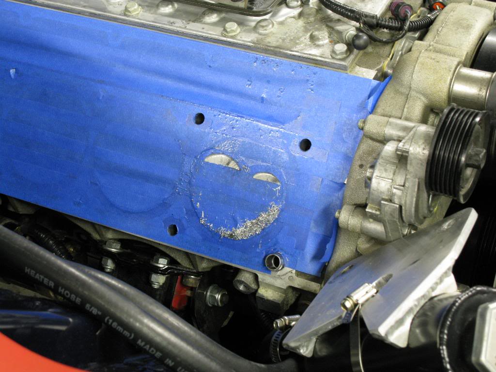
Here is the area all prepped for cutting. All taped off to ensure no metal chips get anywhere unwanted.
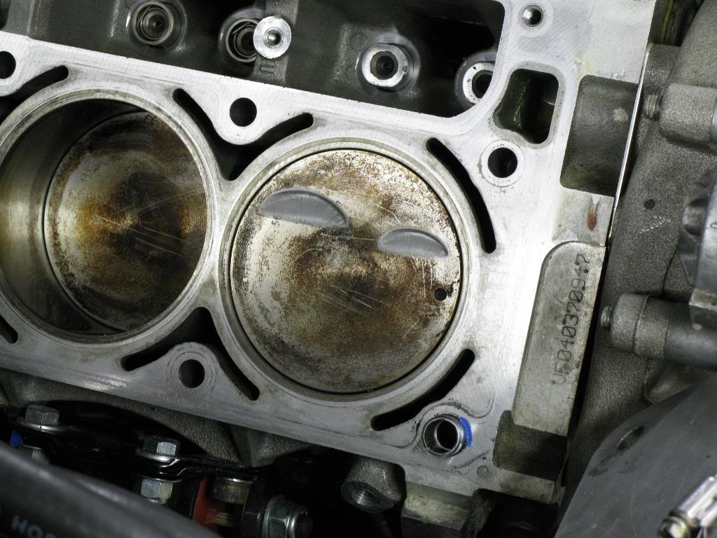
Made the intake and exhaust cuts on one cylinder. This pic is what it looks like when you pull the head off. You can see some chatter in the cuts, but its not too bad.
After I brushed away the shavings I sanded the edges down with some 200 grit sand paper. Finished product.
All its well, clearances are what they should be. Looks like its time to repeat 7 more times!
0.004" clearance on the intake valve.
0.000" clearance on the exhaust valve. Aka, contact.
I was unsatisified that my method of checking PTV clearance was adaquate using the hydraulic lifters (even with the light check spring), so I just modified two stock lifters. I welded the lifters up solid. New PTVC numbers tomorrow....
I put the modified solid lifters in today and remeasured the clearances. I came up with 0.003" intake, and 0.001" exhaust. Then I realized I made a mistake when I was removing the exhaust rocker. I used the same length pushrod (on the adjustable checker) for both intake and exhaust measurements. I then double checked the PR lengths required. The exhaust pushrod needed to be 3/4 of a turn shorter than the intake pushrod, which equates to ~0.0375" difference. That meant that when I measured the clearance on the exhaust valve the valve was 0.037 more closed than it should have been.
So I rechecked, each clearance, making sure to have zero lash and the appropiate pushrod length for each.
I remeasured and got these numbers. The new exhaust number reflects exactly the difference in pushrod length.
Intake: 0.003"
Exhaust: 0.038"
I know if you read through this thread you'll see that I measured about 58 times, and came up with a different result each time. I feel pretty confident that I measured correctly this time. I checked with the dial indicator, and then also with feeler gauges between the valve tip and rocker. Another thing worth noting when measuring is that the tightest intake clearance it occurs as the cam is ramping up in its profile, while the tightest exhaust clearance occurs when the cam is ramping down. Because of that, you have to ensure the lifter is seated up against the cam, and not sticking in the lifter trays. With only a test spring on the valve, it could stick and you would not know. Each time I'd measure I'd push down on the rocker to amke sure the lifter was up against the cam.
Given my results to maintain 0.080" clearance on the intake side, and 0.100" clearance on the exhaust side I would have to cut:
Intake cut: 0.077"
Exhaust cut: 0.062"
Given that I may end up cutting 0.080" on the intake, and 0.065" on the exhaust side.
I think I may actually cut today, or maybe tomorrow.
So I finally made my first cuts. I cut 0.080" on the intake, and 0.065" on the exhaust. That should have given me 0.083" PTVC and 0.103" PTVC respectively. After I made the cuts I measured and came up wiht 0.080" PTVC, and 0.097" PTVC. Looks like there is some spring in the material as it cuts or something. Close enough for government work.
Here is the area all prepped for cutting. All taped off to ensure no metal chips get anywhere unwanted.
Made the intake and exhaust cuts on one cylinder. This pic is what it looks like when you pull the head off. You can see some chatter in the cuts, but its not too bad.
After I brushed away the shavings I sanded the edges down with some 200 grit sand paper. Finished product.
All its well, clearances are what they should be. Looks like its time to repeat 7 more times!
 05-20-10, 10:35 AM
#50
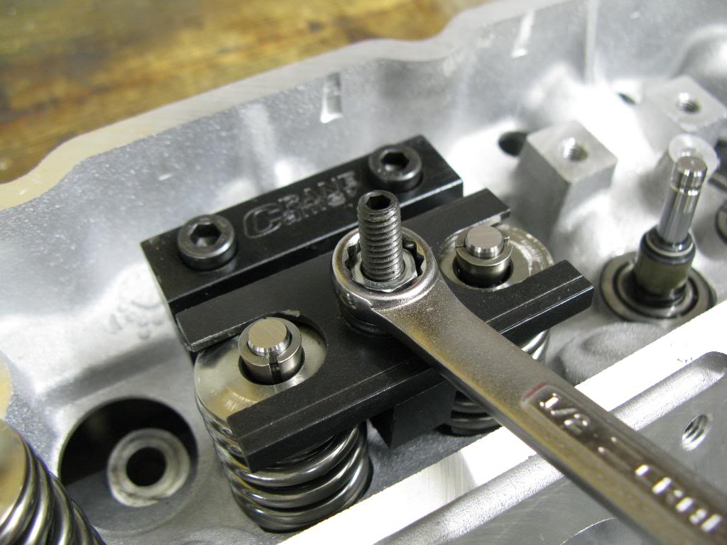
I just used the Crane valve spring compressor tool. That thing is badass, thanks Ray. Some pictures I took while using it.
Springs compressed
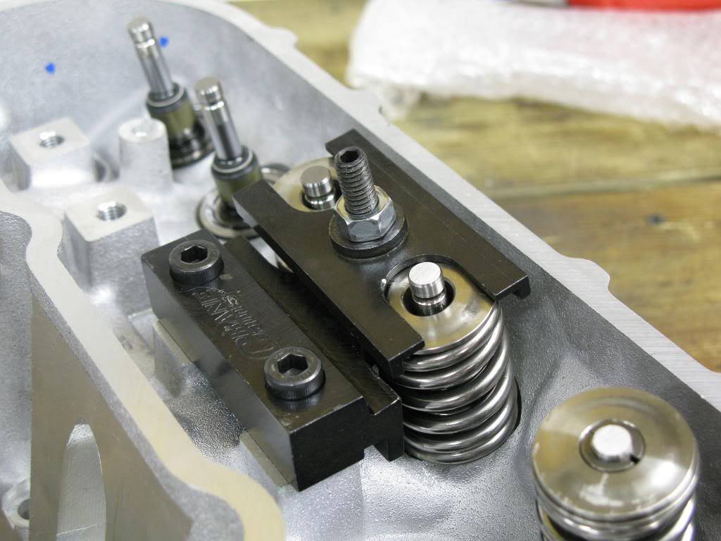
Locks set in place
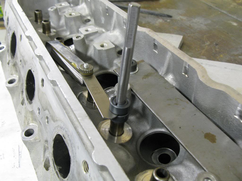
I measured lifter 4 intake and 4 exhaust pushrods to zero lash. I used the adjustable length checker, and moved in increments of 1/4 turn (0.0125"). I'd find the length that was slightly too short, and the length that was too long, so it was between those two, and I averaged the lengths. I did that for all 8 lifters I measured for. The most that I could be off using that method is less than 0.00625", which is close enough for pushrod lengths.
I came up with 7.269" intake, and 7.244" exhaust. All 4 intake were identical, all 4 exhaust were identical. Then add on preload to those numbers. I tried a few different pushrod lengths and figured out what the preload would be.
Prelaod with 7.350" pushrods:
Intake: 0.081"
Exhaust: 0.106"
Preload with 7.325" pushrods:
Intake: 0.056"
Exhaust: 0.081"
I have a few questions. First, why is the length of the intake and exhaust pushrods different? Second, which length pushrod should I choose? Would it make sense to use a different pushrod length on the intake and exhaust? If I was shooting for 0.080" preload it would seem as if that would be the right decision. I would appreciate any pros on the subject to shed some light.
A little info on my setup: LS1 with stock bottom end (pistons flycut with Lindy tool), PRC stg. 2.5 5.3l heads, MS4 cam, LS7 lifters, stock rockers. Need any more info please ask.
Springs compressed
Locks set in place
I measured lifter 4 intake and 4 exhaust pushrods to zero lash. I used the adjustable length checker, and moved in increments of 1/4 turn (0.0125"). I'd find the length that was slightly too short, and the length that was too long, so it was between those two, and I averaged the lengths. I did that for all 8 lifters I measured for. The most that I could be off using that method is less than 0.00625", which is close enough for pushrod lengths.
I came up with 7.269" intake, and 7.244" exhaust. All 4 intake were identical, all 4 exhaust were identical. Then add on preload to those numbers. I tried a few different pushrod lengths and figured out what the preload would be.
Prelaod with 7.350" pushrods:
Intake: 0.081"
Exhaust: 0.106"
Preload with 7.325" pushrods:
Intake: 0.056"
Exhaust: 0.081"
I have a few questions. First, why is the length of the intake and exhaust pushrods different? Second, which length pushrod should I choose? Would it make sense to use a different pushrod length on the intake and exhaust? If I was shooting for 0.080" preload it would seem as if that would be the right decision. I would appreciate any pros on the subject to shed some light.
A little info on my setup: LS1 with stock bottom end (pistons flycut with Lindy tool), PRC stg. 2.5 5.3l heads, MS4 cam, LS7 lifters, stock rockers. Need any more info please ask.