Mefarri's 1995 FD LS3 turbo build


 05-31-12, 04:01 PM
#104
Alright so here’s some updates. Buncha pictures coming atcha.
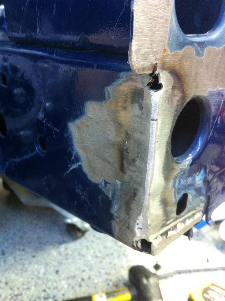
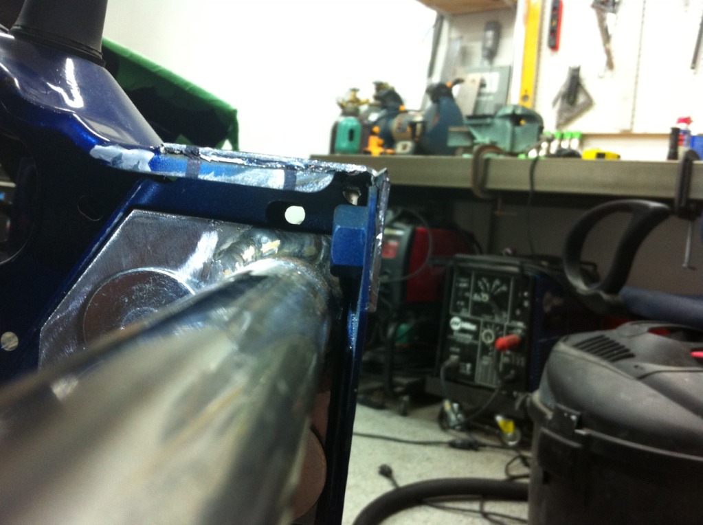
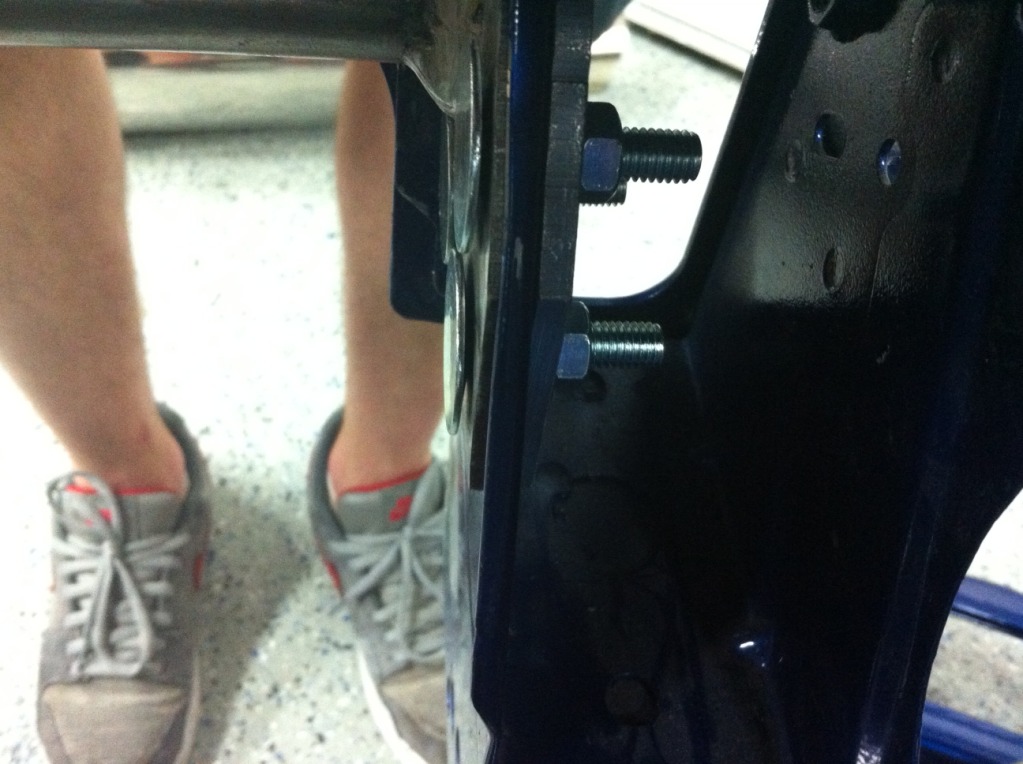
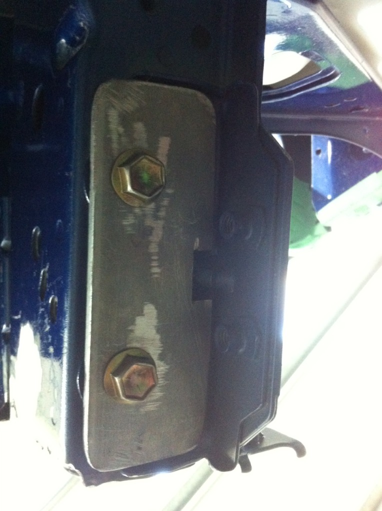
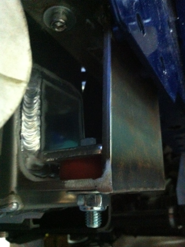
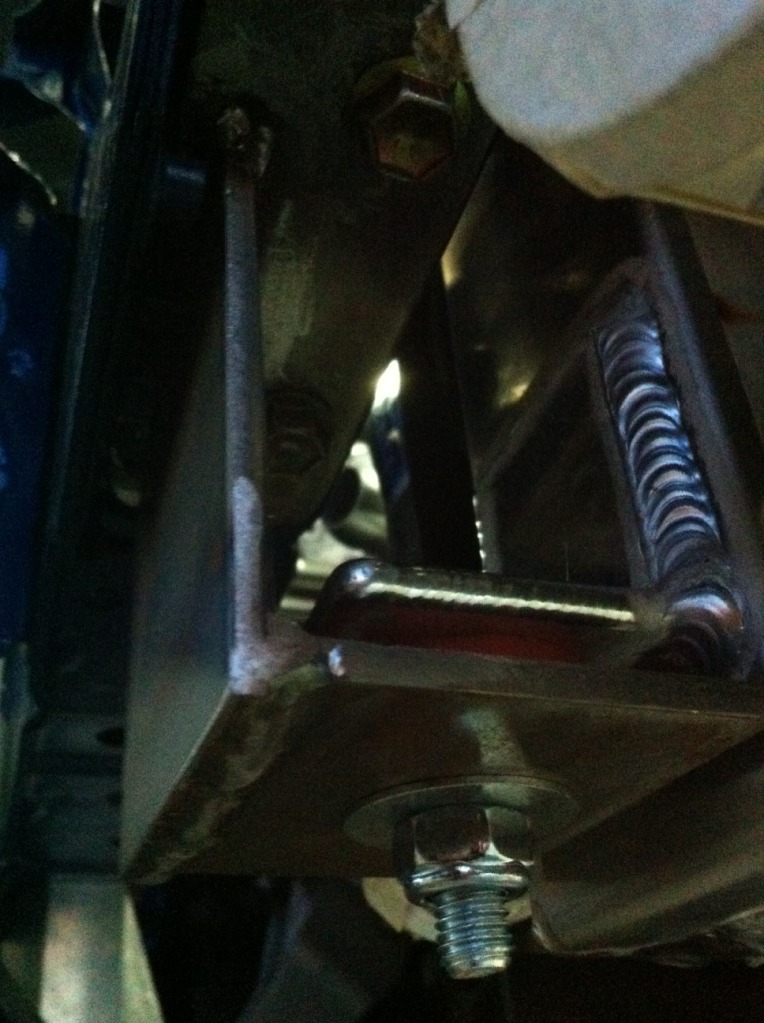
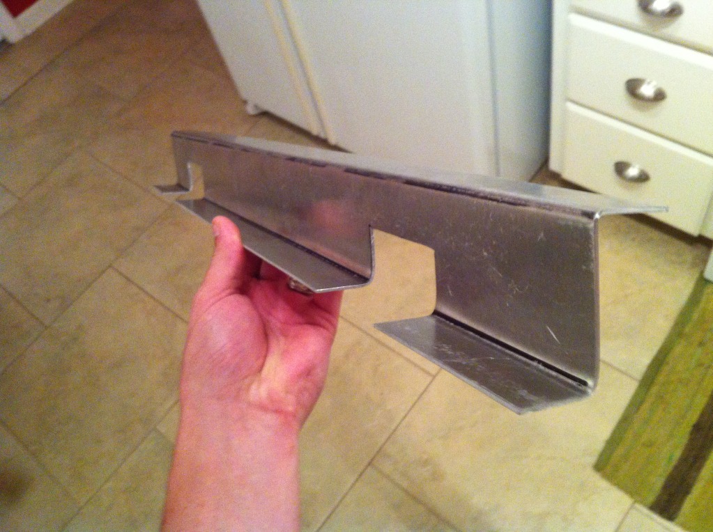
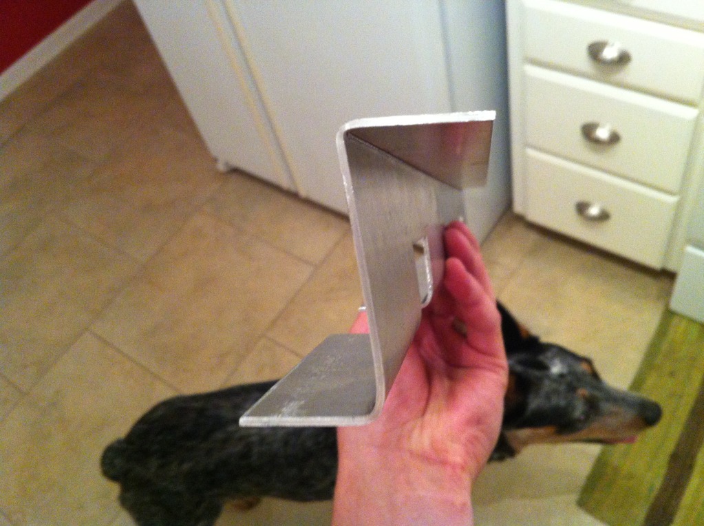
Last time I updated, I had tacked the cross bar to the end plates and had the circle holes drilled. When I was trying to figure out a way to get the cross bar to fit with the wider cored radiator, I was negative about 1/2” in side to side clearance due to the heads of the bolts sticking off the plates. Studs wouldn’t work because the bar is practically a press fit between the frame rails. After talking to Zac a while and trying to figure out a way to do this, he remembered about the kind of bolts that have squared flanges (called elevator bolts) and I was able to find them with flat heads on Mcmaster Carr. That gave me a positive side to side clearance of like 1”. So I had to take my dremel and square off each round hole so the bolts could sit down flush. I think they stick off the plate like 1/16” or so. I also made identical 3/16” plates for the inside of the frame rail so that the body of the car gets sandwiched between the 2. It came out exactly like I’d hoped. I can pick up the front end of the car by the bar so it’s nice and strong. The cross bar is as far up and to the front of the car as possible while still allowing the bumper support bolts to thread out the back as you can see in the pic. I also welded some tabs on it for the center 2 bumper mounting points and tapped them for M8 bolts.
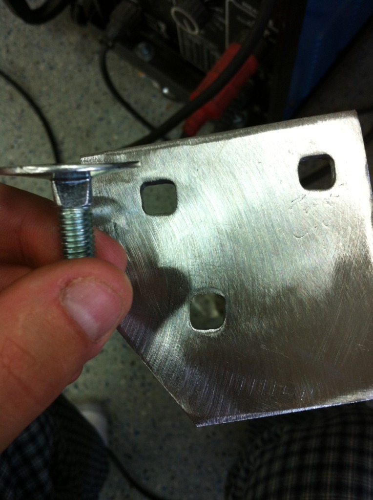
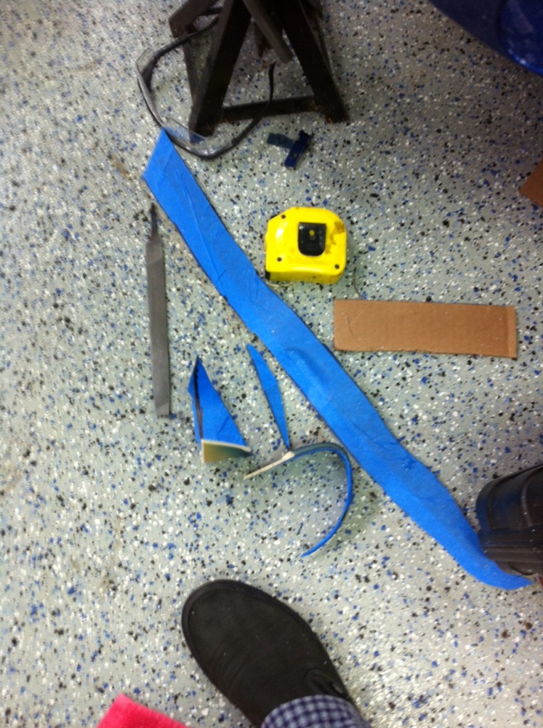
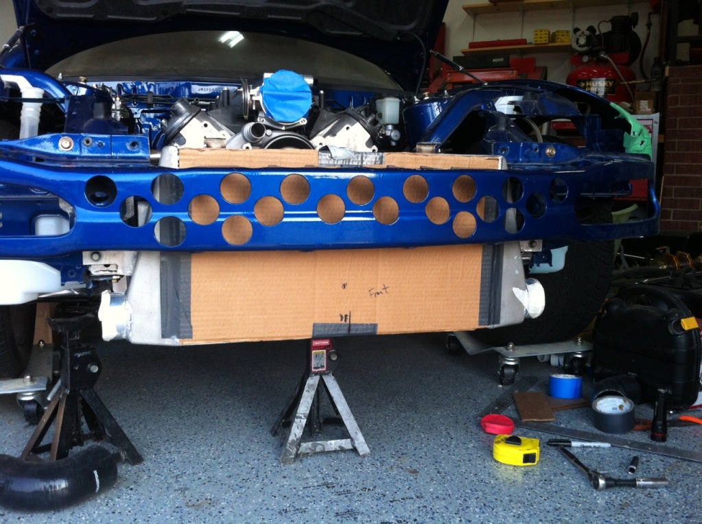
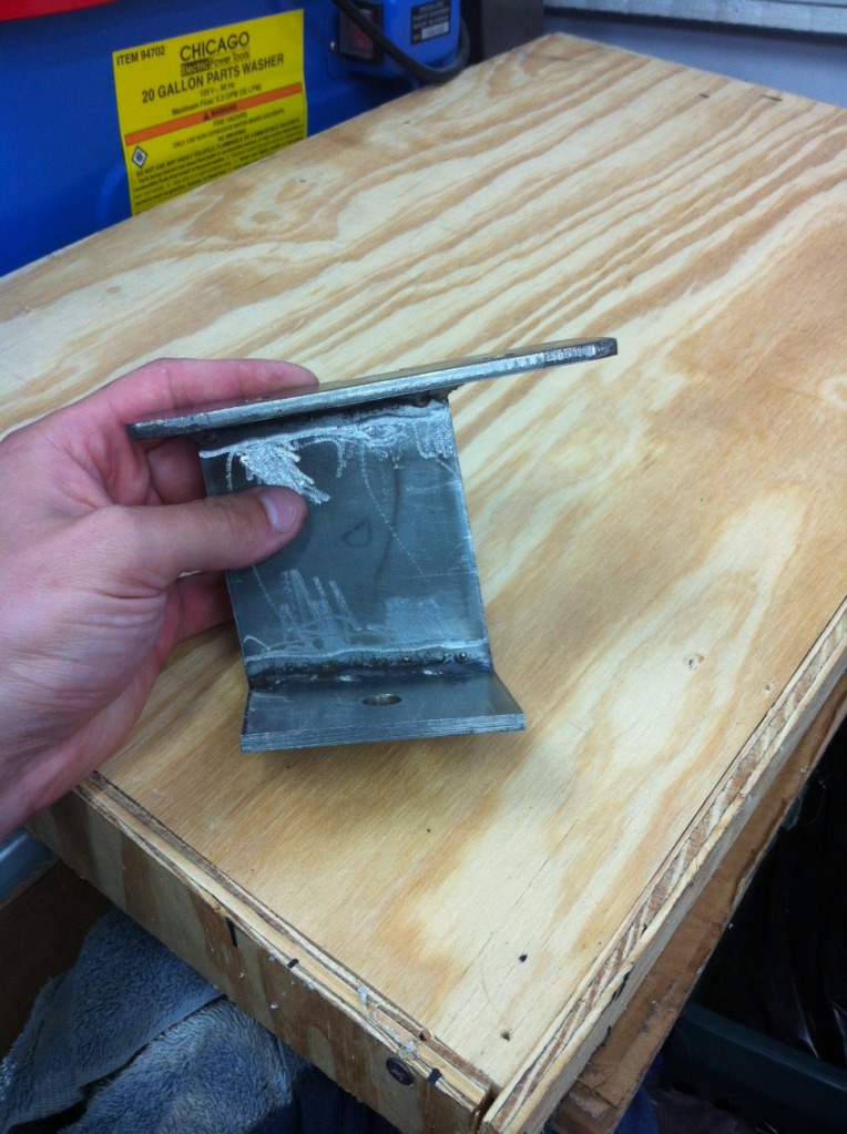
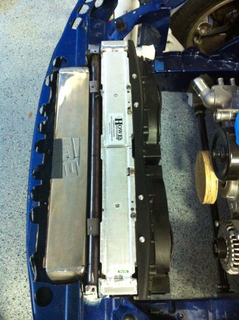
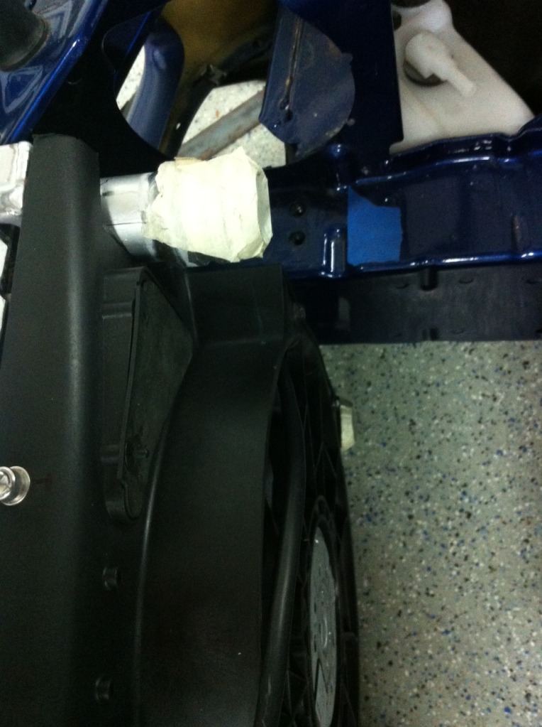
Next thing was getting the intercooler mounted. I made some marks on my floor based off where the mouth of the factory bumper was in relation to the available space and then some marks based off the most forward I could push the intercooler based off my cut up bumper support (which I’d trimmed as much as possible while still retaining the 4 bumper mounting holes on the inside of the upper mouth.) That gave me like 1.75” of bumper mouth I needed to cut. With some instruction by Nick, I marked some lines on the mouth of the bumper and then taped it all up and went to town with a jigsaw and an airsaw. Came out great. No chipping at all and a nice smooth surface. The key is making sure your blade is cutting the right direction so you don’t get tearout. Now I’ve got around 1/8”- 1/4" clearance between the bumper and intercooler. The mounts for the intercooler I just made out of some 1” x 3/8” aluminum bar. I welded a couple pieces into an acute L shape and then welded them to the intercooler end tanks. Not the prettiest welds in the world but they’re strong. I beveled the ends of the plate and made 2 passes so penetration is good. The reason they’re not as pretty as some you’ll see in a minute is that during this time, I realized I was overheating my 3/32” tungsten and it was contaminating my puddles. After these I switch to 1/8” and it worked much better. I was going to add some more mount off the top but the intercooler is super solid with just those 2, so there’s no need. I’m really happy with how it came out. It used the lower 2 bumper support mounting holes.
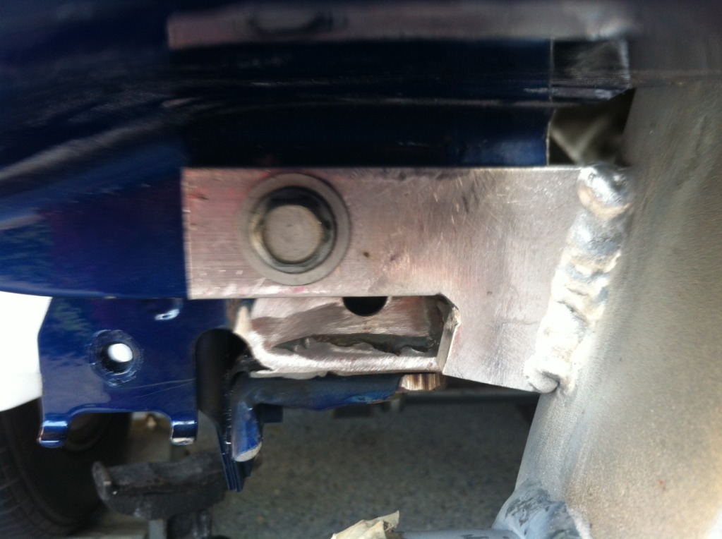
Last time I updated, I had tacked the cross bar to the end plates and had the circle holes drilled. When I was trying to figure out a way to get the cross bar to fit with the wider cored radiator, I was negative about 1/2” in side to side clearance due to the heads of the bolts sticking off the plates. Studs wouldn’t work because the bar is practically a press fit between the frame rails. After talking to Zac a while and trying to figure out a way to do this, he remembered about the kind of bolts that have squared flanges (called elevator bolts) and I was able to find them with flat heads on Mcmaster Carr. That gave me a positive side to side clearance of like 1”. So I had to take my dremel and square off each round hole so the bolts could sit down flush. I think they stick off the plate like 1/16” or so. I also made identical 3/16” plates for the inside of the frame rail so that the body of the car gets sandwiched between the 2. It came out exactly like I’d hoped. I can pick up the front end of the car by the bar so it’s nice and strong. The cross bar is as far up and to the front of the car as possible while still allowing the bumper support bolts to thread out the back as you can see in the pic. I also welded some tabs on it for the center 2 bumper mounting points and tapped them for M8 bolts.
Next thing was getting the intercooler mounted. I made some marks on my floor based off where the mouth of the factory bumper was in relation to the available space and then some marks based off the most forward I could push the intercooler based off my cut up bumper support (which I’d trimmed as much as possible while still retaining the 4 bumper mounting holes on the inside of the upper mouth.) That gave me like 1.75” of bumper mouth I needed to cut. With some instruction by Nick, I marked some lines on the mouth of the bumper and then taped it all up and went to town with a jigsaw and an airsaw. Came out great. No chipping at all and a nice smooth surface. The key is making sure your blade is cutting the right direction so you don’t get tearout. Now I’ve got around 1/8”- 1/4" clearance between the bumper and intercooler. The mounts for the intercooler I just made out of some 1” x 3/8” aluminum bar. I welded a couple pieces into an acute L shape and then welded them to the intercooler end tanks. Not the prettiest welds in the world but they’re strong. I beveled the ends of the plate and made 2 passes so penetration is good. The reason they’re not as pretty as some you’ll see in a minute is that during this time, I realized I was overheating my 3/32” tungsten and it was contaminating my puddles. After these I switch to 1/8” and it worked much better. I was going to add some more mount off the top but the intercooler is super solid with just those 2, so there’s no need. I’m really happy with how it came out. It used the lower 2 bumper support mounting holes.
05-31-12, 04:02 PM
#105
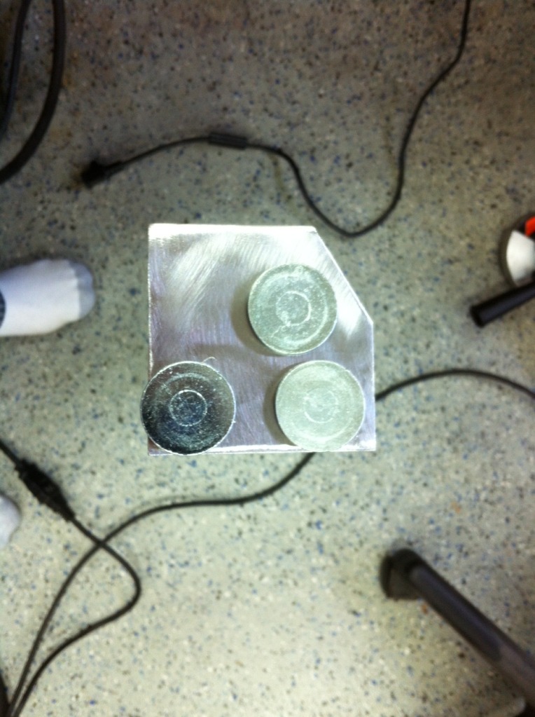
Next up was AC condenser mounting. I’m using the same one that Justin uses which turned out to be the perfect size. Again, since the engine bay is growing increasingly tighter on space, keeping everything tucked up was paramount. I decided to mount it directly to the intercooler. I took some more of that 1” x 3/8” aluminum bar and welded it to each other, and then to the end tanks. One thing that almost became an issue was how to tighten the bolts holding it to the intercooler, but with proper planning, I can sneak a wrench to the underside. I just had to cut off a couple inches of the side mounting tabs that weren’t being used to be able to slide it up and out of the fixed mounting brackets- since it sits 1/8” off the intercooler, I couldn’t slide the fitting ends under the brackets. But this works perfect. I then countersunk the mounting holes so I could tuck the radiator up as close as possible later and installed it to the intercooler with much rejoicing.
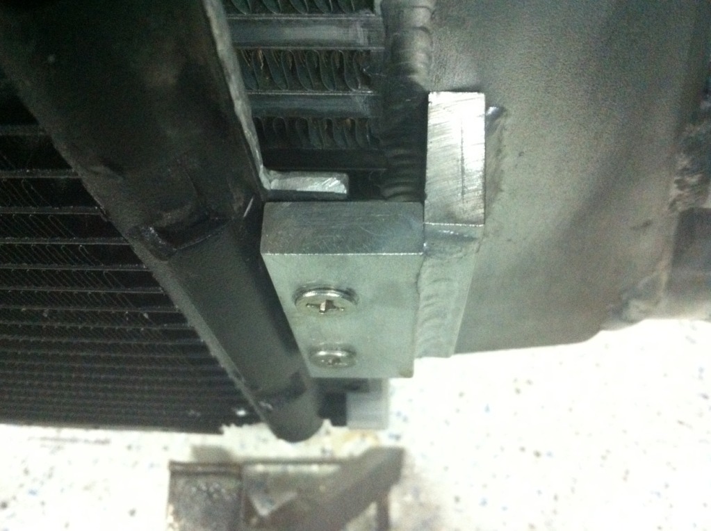
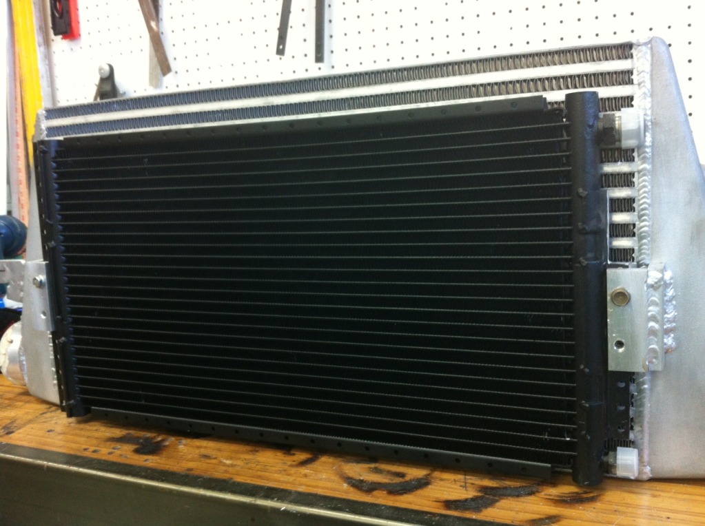
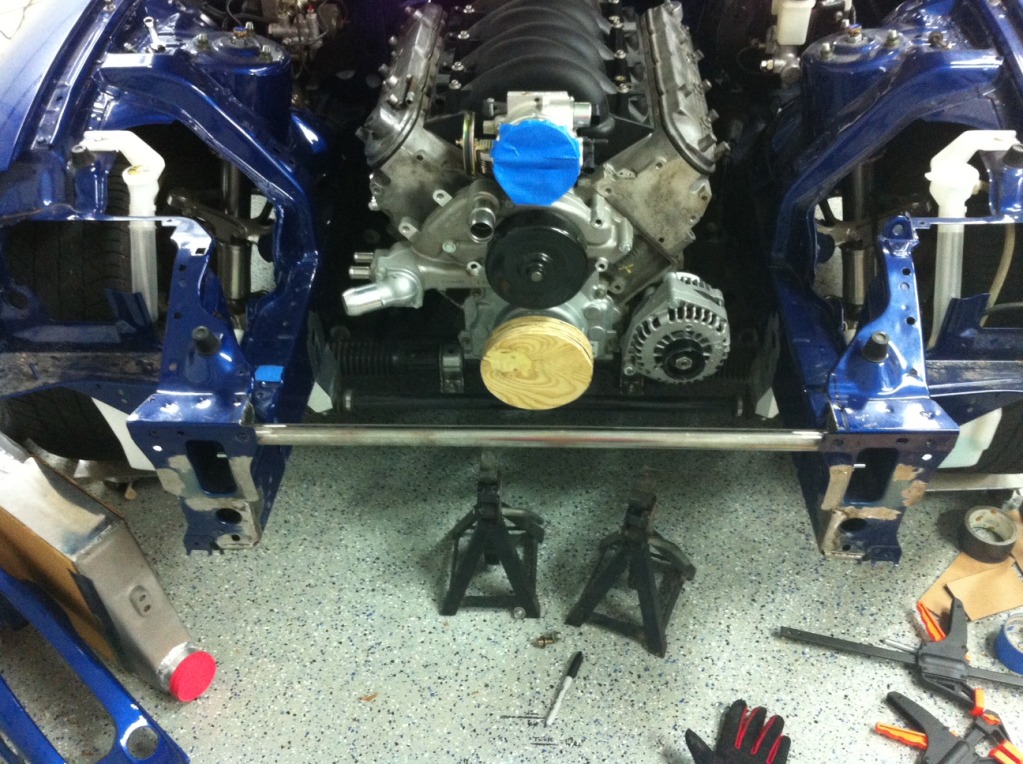
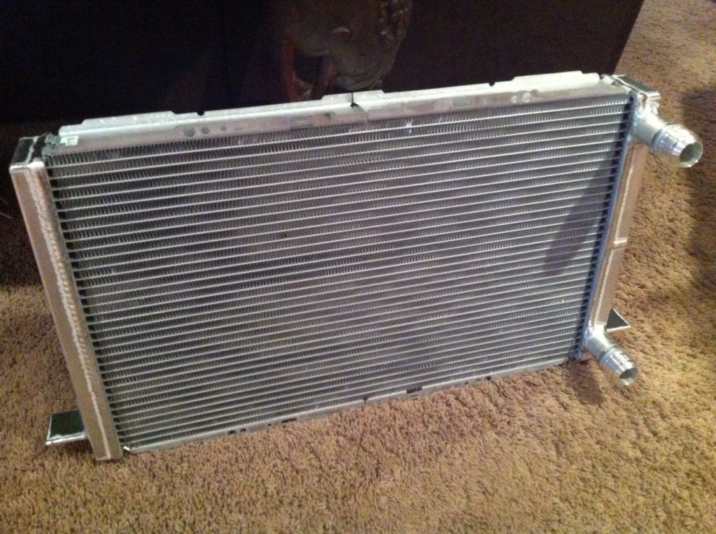
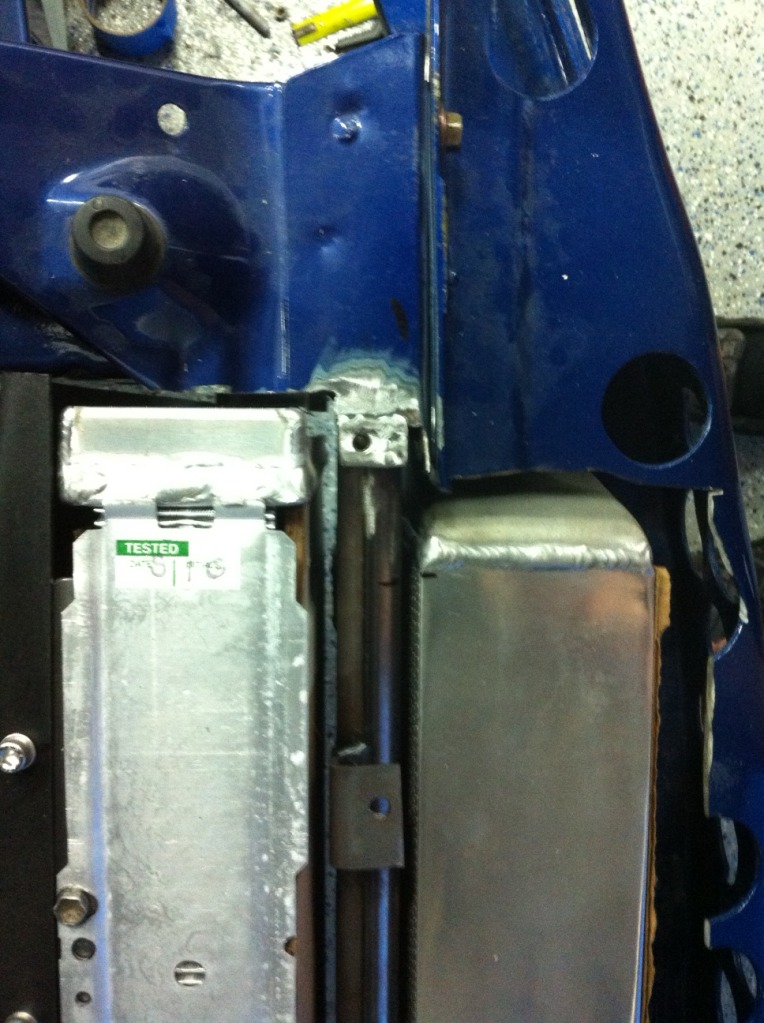
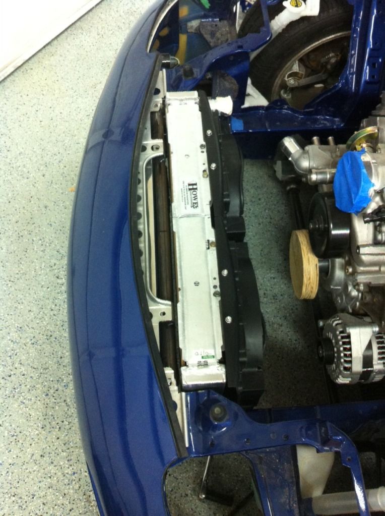
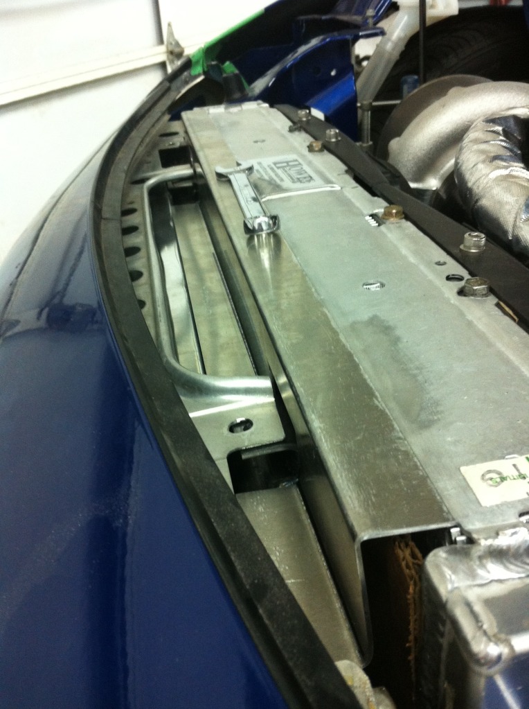
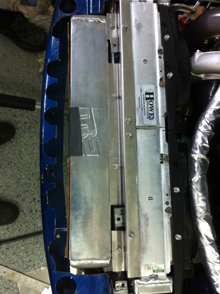
Then the radiator showed up. It’s beautiful and exactly like I asked for. Howe really does fantastic work. And at only $320 with the 2 -20 AN fittings welded on and the mounting tabs, it’s a ******* steal. It’s pretty much identical to what Zac is using. Core is 24”x15”, dual core, dual pass. End tanks bring it to a total width of 26.5” which is 1.5” narrower than the frame rails. I had to cut some of the upper body at the edges to fit it side to side, but was able to retain the outer bumper mounting tabs. (I actually cut them off a while back because I figured I’d need the space but they fit perfect so I welded them back on. Yay for saving them just in case.) Then I pushed it as far forward as possible- which I left at about 1/4” clearance between the end tank and cross bar, and then as far up as possible- leaving about 1/2” clearance to the hood. I bent the mounting tabs flat on top for more clearance, and for shroud and fan mounting provisions. For the record, ground clearance was a big point of concern for me since most of this driving will be on the street. The way everything is mounted now, the intercooler sits 1” above the front lip mounting bolts, the AC condenser is above that slightly, and the radiator lower tabs sit about 1/2" higher which is perfect because I’ll be using those for attaching the backside of the lower diffuser I’ll build. Just like I planned it out on paper.
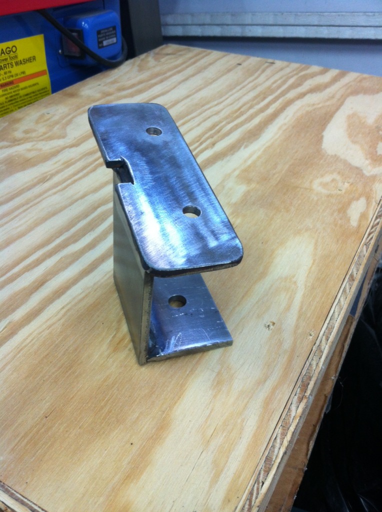
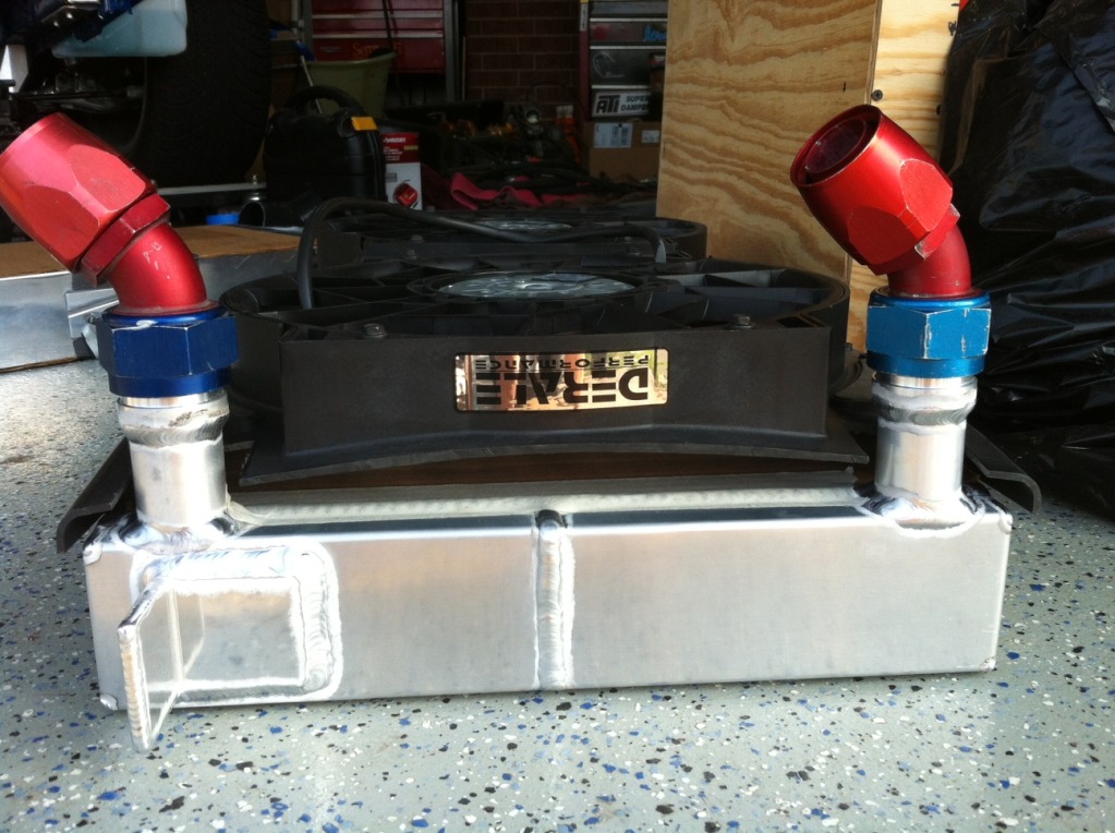
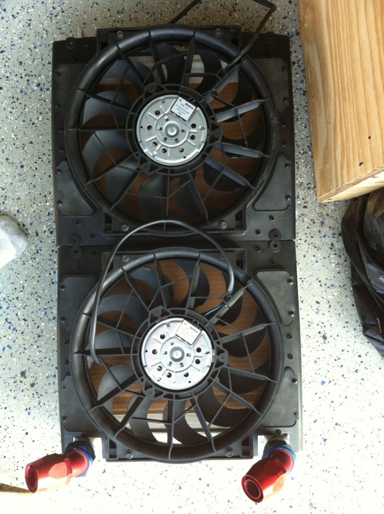
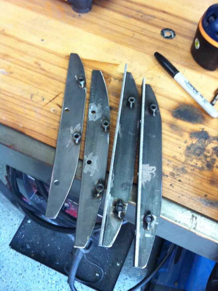
The next thing was the actual mounting of the radiator. The reason I got the radiator made with the L mounting brackets was because I was making the lower pedestals for them to rest on. The pedestals are made out of 3/16” mild plate. I made the plate that mounts to the underside of the frame rail and then came off of it to build the rest. The radiator actually sits on 2 pieces of 1 1/2” OD 500+ degree silicone rubber that I cut down to 1/2" tall and is attached via 10mm bolts with lock nuts. It’s so solid it holds it in place with no upper mount at all. And it’s located exactly where I wanted it to be. 1/4" off the cross bar and 1/8” off the AC condenser. Couldn’t be happier. The last thing was mounting the fans to the radiator. I cut down the sides of the fans as far as I could and was able to get their combined width down to just under 26.75” so the driver’s side will hang off the side of the end tank about 1/4". That’s the best I could do. Not that you’ll ever notice because it will all be covered up by shrouding. I then cut the notches out of the passenger side fan so that it could fit around the fitting tubes. I had them extend the fittings off the face of the end tank so that they’d clear with the fans installed. That would have sucked had I forgotten that. I used my belt sander to sand all the edges I cut flat and the seam where the 2 fans meet is flush down the whole middle. Then it was just how to mount the fans to the radiator, keeping them as close to the radiator as possible. I ended up using some 1/ �” flat & 1 1/4” 1/8” plate and angle iron for mounting. Everything came out great and the fans slide over the 2 and are adhered via bolts to nuts I welded on the underside since tightening them would have been impossible. I had to cut down the ends that went on the inside of the fan since the shroud on them tapers, and that allowed the fans to pull in nice and tight to the radiator. The center most part of the fan sits 1/8” off the core.
The only thing left is to shroud them and replace the random bolts I used for the radiator to bracket mounting with the nice looking allen bolts I ordered last night. I also ordered some .032” aluminum sheet for shrouding the sides of the radiator up to the intercooler and also for shrouding the upper radiator to the cross bar to also act as the upper radiator mounting structure.
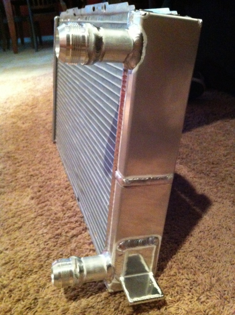
Then the radiator showed up. It’s beautiful and exactly like I asked for. Howe really does fantastic work. And at only $320 with the 2 -20 AN fittings welded on and the mounting tabs, it’s a ******* steal. It’s pretty much identical to what Zac is using. Core is 24”x15”, dual core, dual pass. End tanks bring it to a total width of 26.5” which is 1.5” narrower than the frame rails. I had to cut some of the upper body at the edges to fit it side to side, but was able to retain the outer bumper mounting tabs. (I actually cut them off a while back because I figured I’d need the space but they fit perfect so I welded them back on. Yay for saving them just in case.) Then I pushed it as far forward as possible- which I left at about 1/4” clearance between the end tank and cross bar, and then as far up as possible- leaving about 1/2” clearance to the hood. I bent the mounting tabs flat on top for more clearance, and for shroud and fan mounting provisions. For the record, ground clearance was a big point of concern for me since most of this driving will be on the street. The way everything is mounted now, the intercooler sits 1” above the front lip mounting bolts, the AC condenser is above that slightly, and the radiator lower tabs sit about 1/2" higher which is perfect because I’ll be using those for attaching the backside of the lower diffuser I’ll build. Just like I planned it out on paper.
The next thing was the actual mounting of the radiator. The reason I got the radiator made with the L mounting brackets was because I was making the lower pedestals for them to rest on. The pedestals are made out of 3/16” mild plate. I made the plate that mounts to the underside of the frame rail and then came off of it to build the rest. The radiator actually sits on 2 pieces of 1 1/2” OD 500+ degree silicone rubber that I cut down to 1/2" tall and is attached via 10mm bolts with lock nuts. It’s so solid it holds it in place with no upper mount at all. And it’s located exactly where I wanted it to be. 1/4" off the cross bar and 1/8” off the AC condenser. Couldn’t be happier. The last thing was mounting the fans to the radiator. I cut down the sides of the fans as far as I could and was able to get their combined width down to just under 26.75” so the driver’s side will hang off the side of the end tank about 1/4". That’s the best I could do. Not that you’ll ever notice because it will all be covered up by shrouding. I then cut the notches out of the passenger side fan so that it could fit around the fitting tubes. I had them extend the fittings off the face of the end tank so that they’d clear with the fans installed. That would have sucked had I forgotten that. I used my belt sander to sand all the edges I cut flat and the seam where the 2 fans meet is flush down the whole middle. Then it was just how to mount the fans to the radiator, keeping them as close to the radiator as possible. I ended up using some 1/ �” flat & 1 1/4” 1/8” plate and angle iron for mounting. Everything came out great and the fans slide over the 2 and are adhered via bolts to nuts I welded on the underside since tightening them would have been impossible. I had to cut down the ends that went on the inside of the fan since the shroud on them tapers, and that allowed the fans to pull in nice and tight to the radiator. The center most part of the fan sits 1/8” off the core.
The only thing left is to shroud them and replace the random bolts I used for the radiator to bracket mounting with the nice looking allen bolts I ordered last night. I also ordered some .032” aluminum sheet for shrouding the sides of the radiator up to the intercooler and also for shrouding the upper radiator to the cross bar to also act as the upper radiator mounting structure.
 05-31-12, 04:03 PM
#107
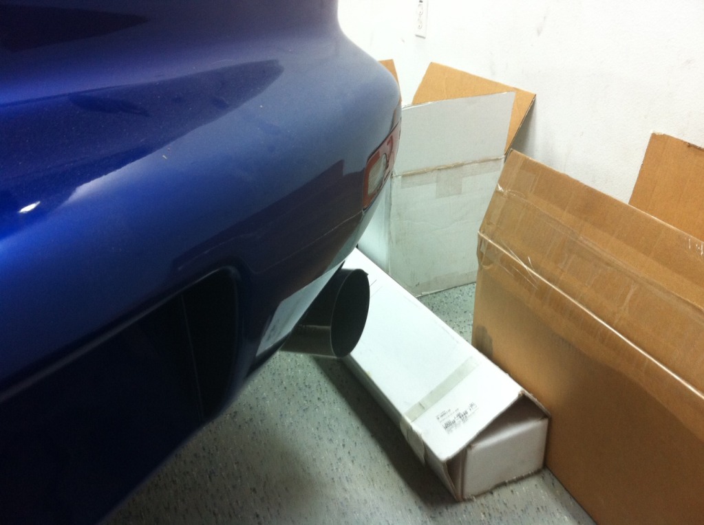
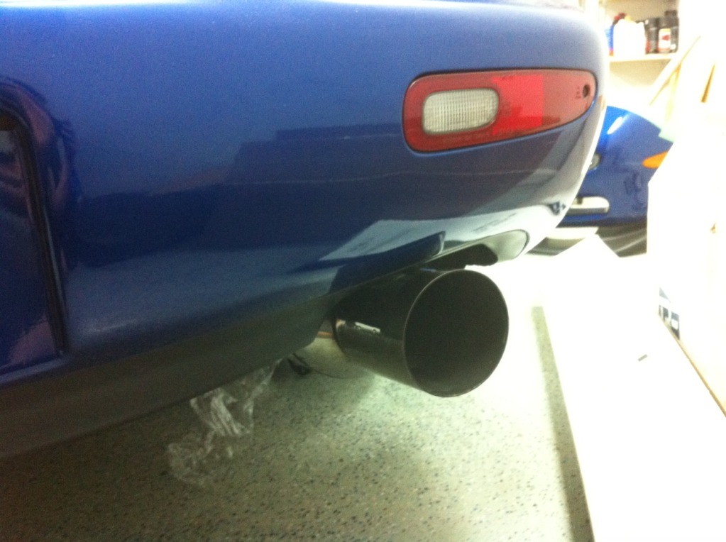
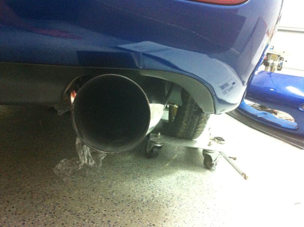
I also met Lane (halspec) in Memphis a few weeks ago and picked up a really nice Greddy Evo 2 catback for the FD from him. It’s full 3.5” ceramic coated piping with a nice large, offset canister that sits up into the bumper so ground clearance is nice. It looks great, and isn’t ricey looking even with the large tip. I love the way it looks. I’ll cut off the flange on the end and use a v band.
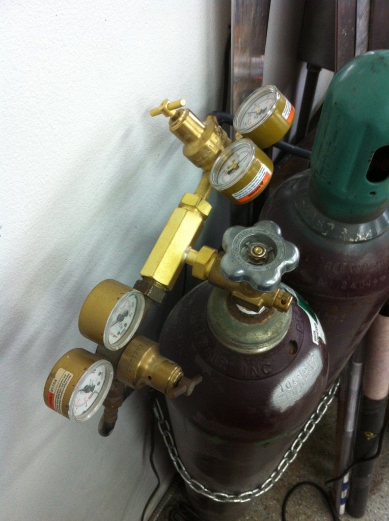
I also got a bunch of TIG pieces in prepping for making the manifolds. Got this T so I can use 2 regulators off one bottle so I can use a back purge setup, and some gas lenses and cups. I also cut up 10 stainless pieces for practicing on once I get ready to do that. It will be the next thing I do I think.
So that’s all the updates I have as of now. The whole front end is pretty much done minus mounting the oil cooler which I’ll tackle soon. And that feels good. Making some good progress lately. Everything came out exactly like I’d hoped. Everything is fully serviceable, strong and usually over engineered which makes me happy.
06-01-12, 11:26 PM
#109
Thanks. I've been trying to get a mod to move my thread back to the Build section so it can see more traffic. But they never answer me...
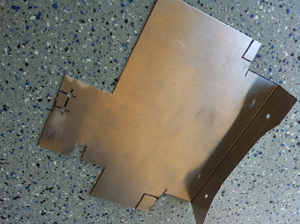
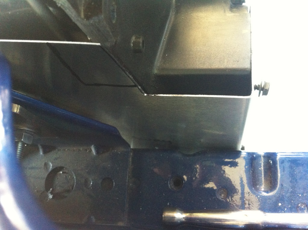
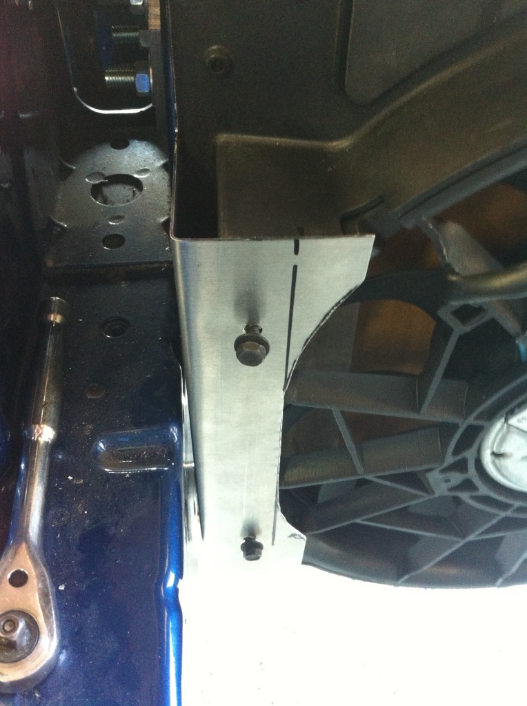
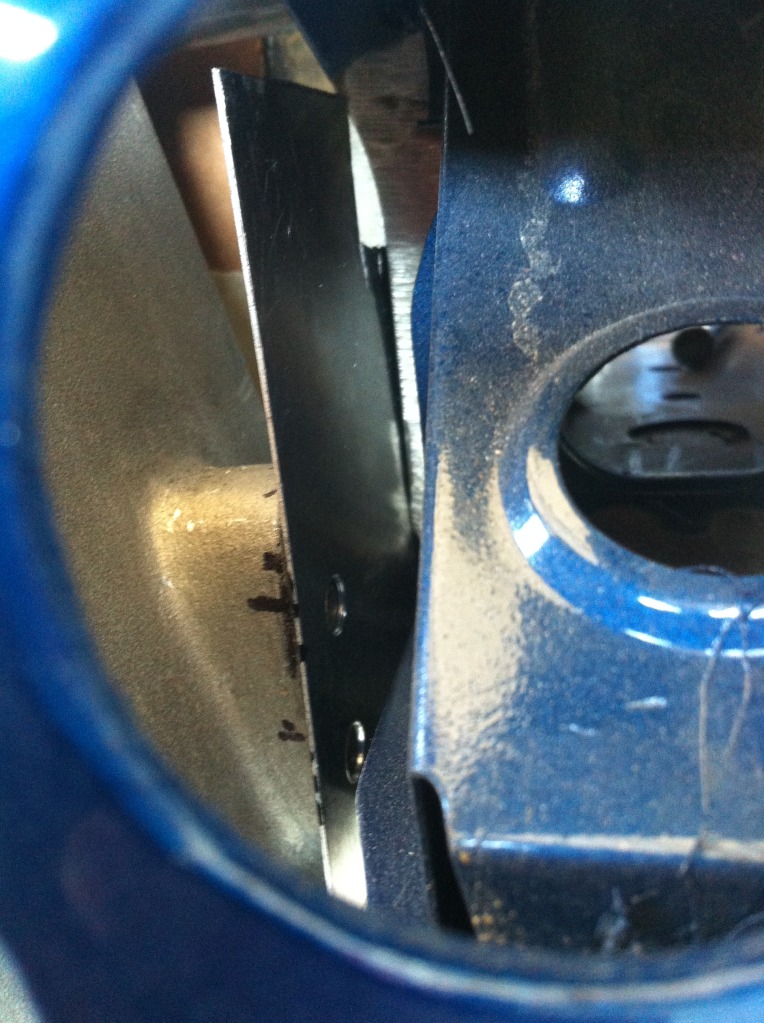
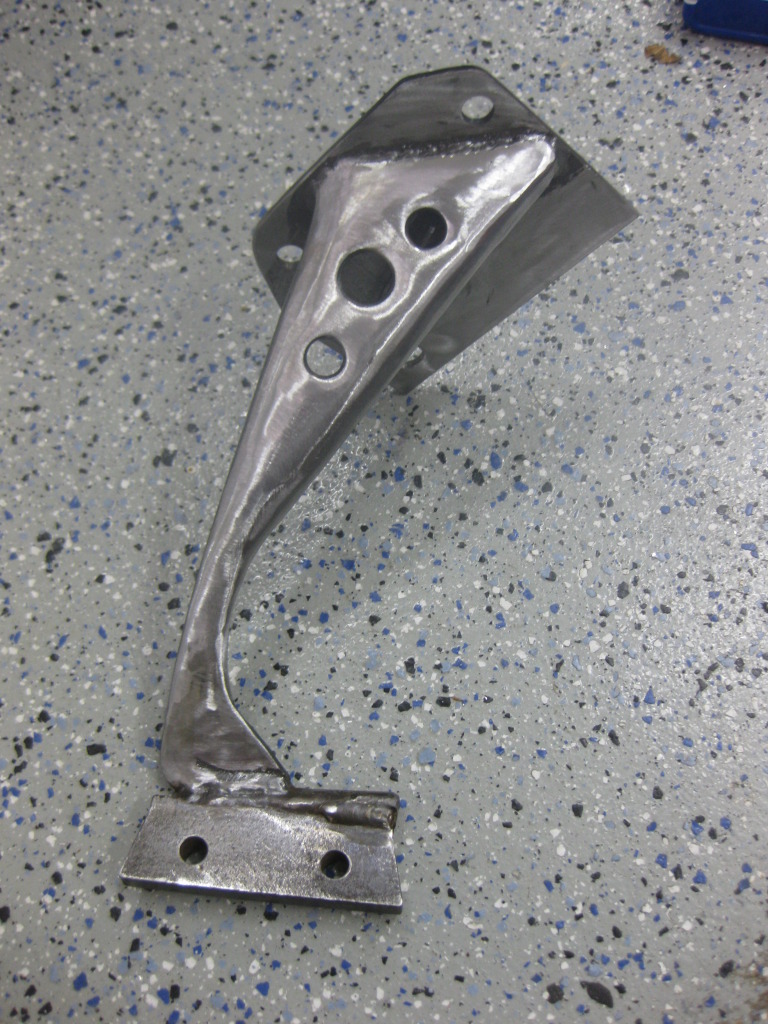
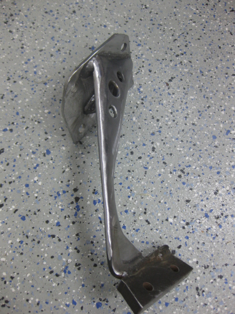
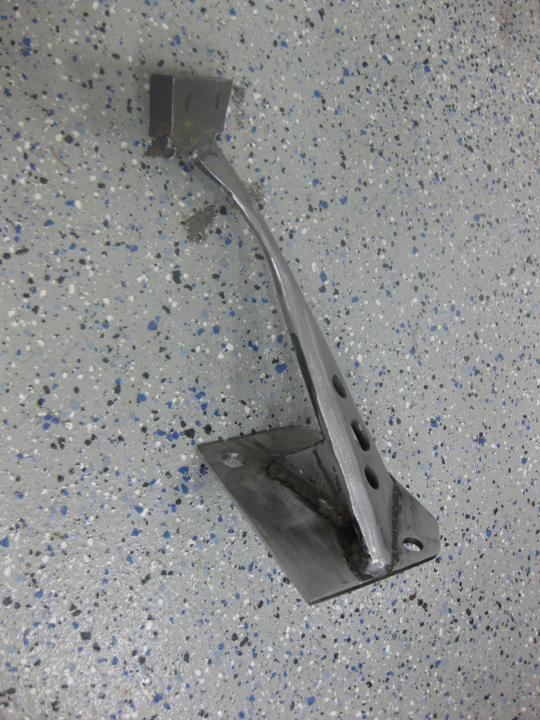
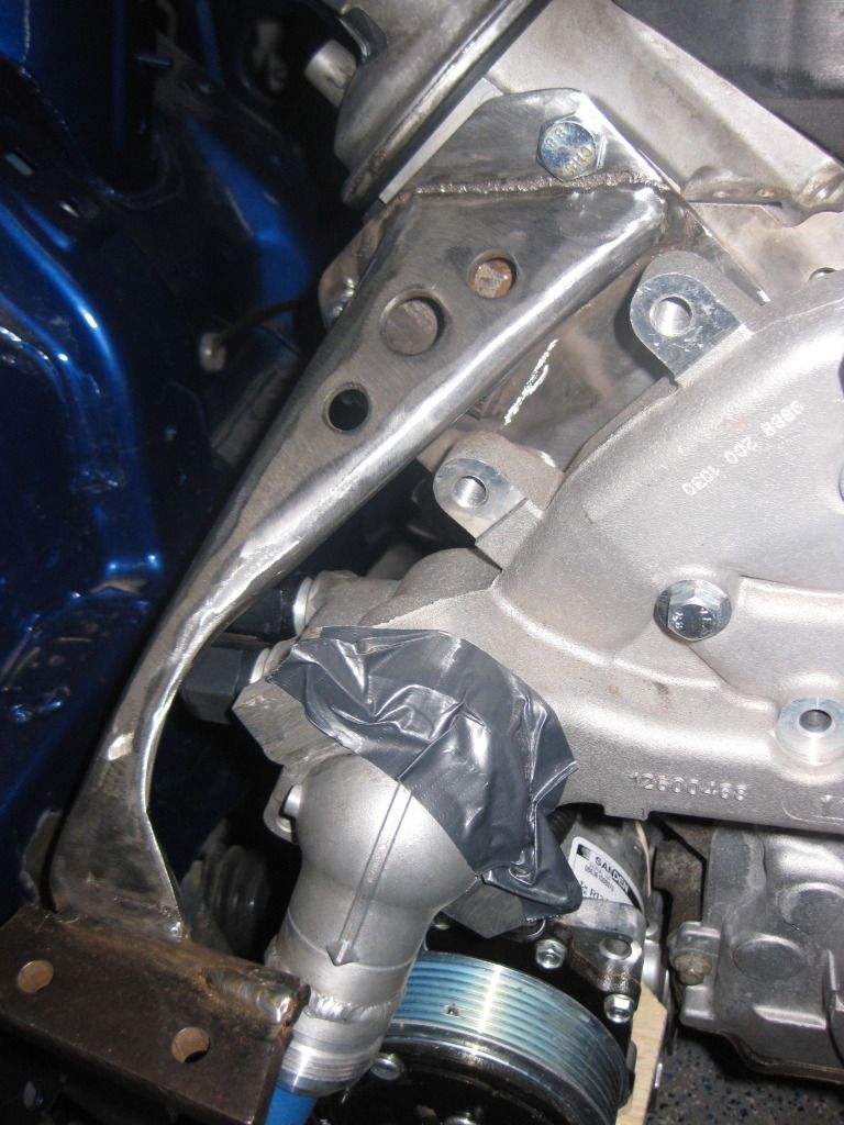
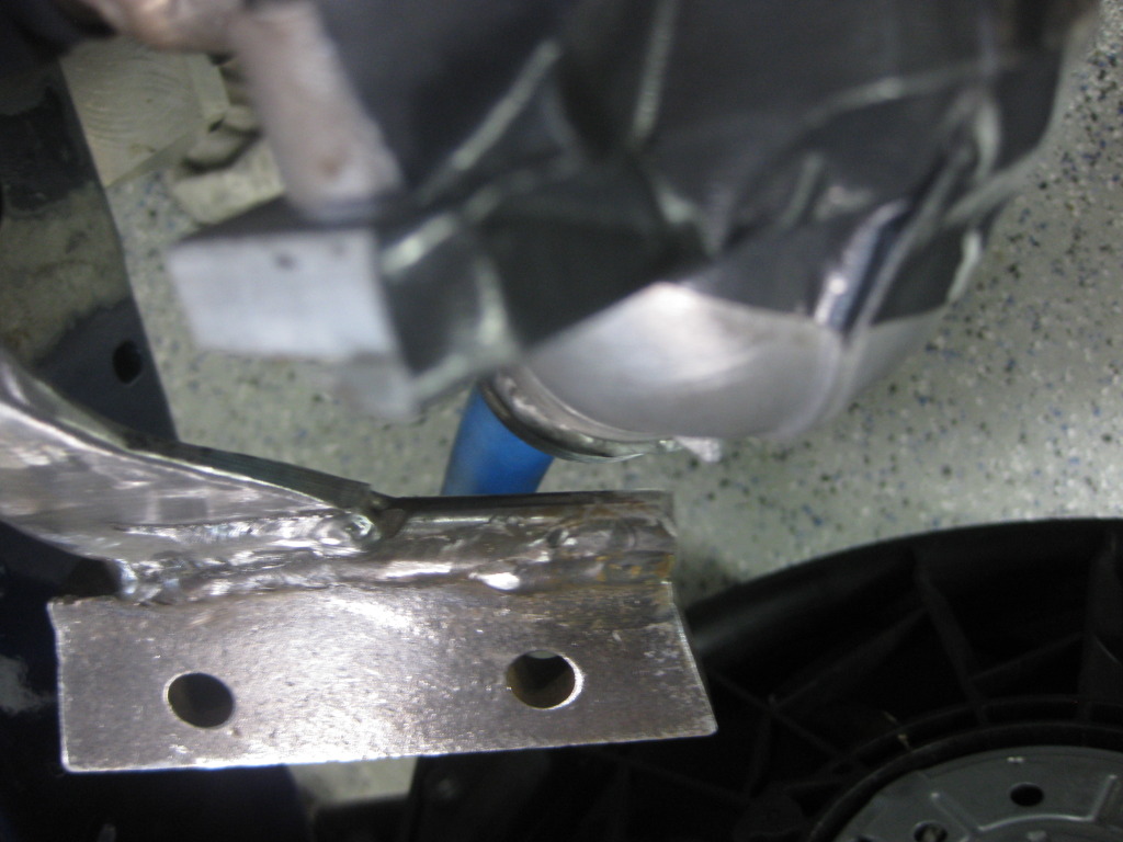
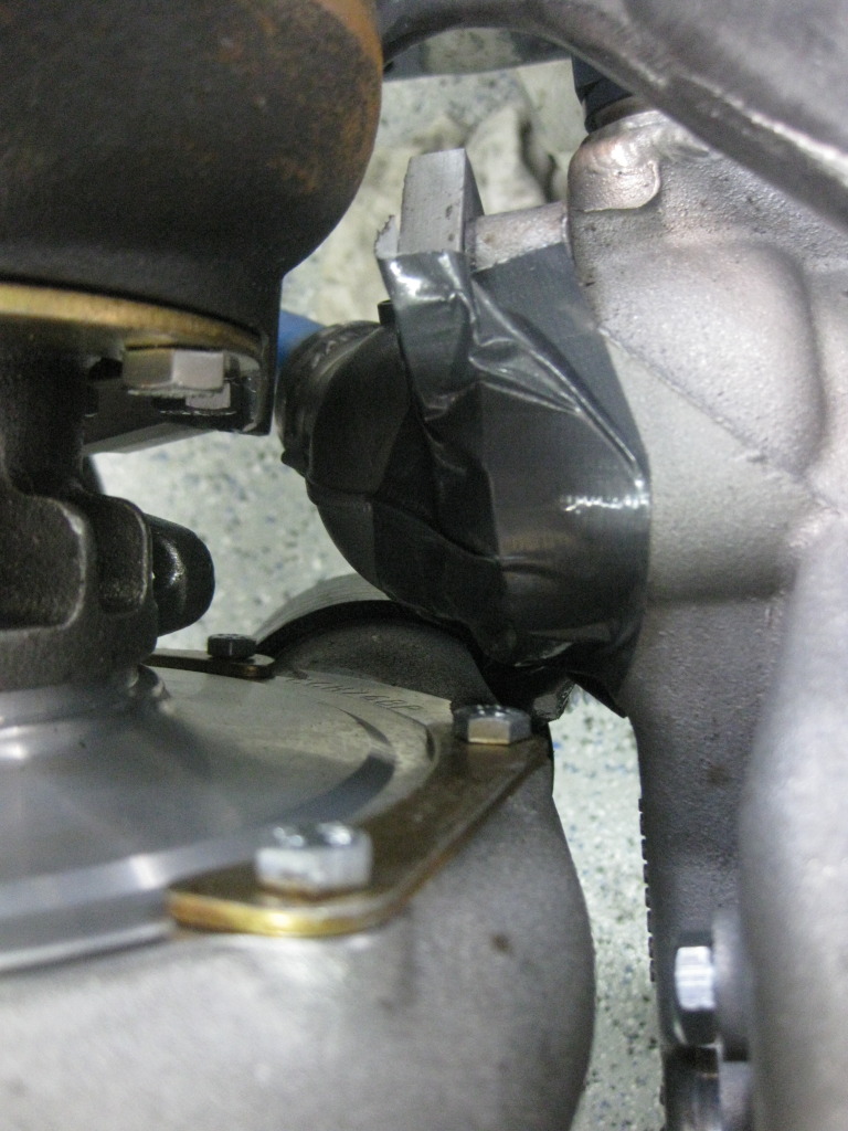
Made the brackets for the oil cooler today. I had to offset it slightly since the coupler from the intercooler took up some space. I had to trim the coupler .75" to get it to pull in tighter. Coverage across the opening is perect though. It covers it entirely. In the pics I'm just holding it in place so it's not level or anything. I'll be building some shrouding later once it's mounted. I didn't drill the holes in the body or bumper support yet for mounting as I'm going to wait until the turbo kit is done to make sure I don't have to re do the location. Other than a few holes drilled, it's done though.
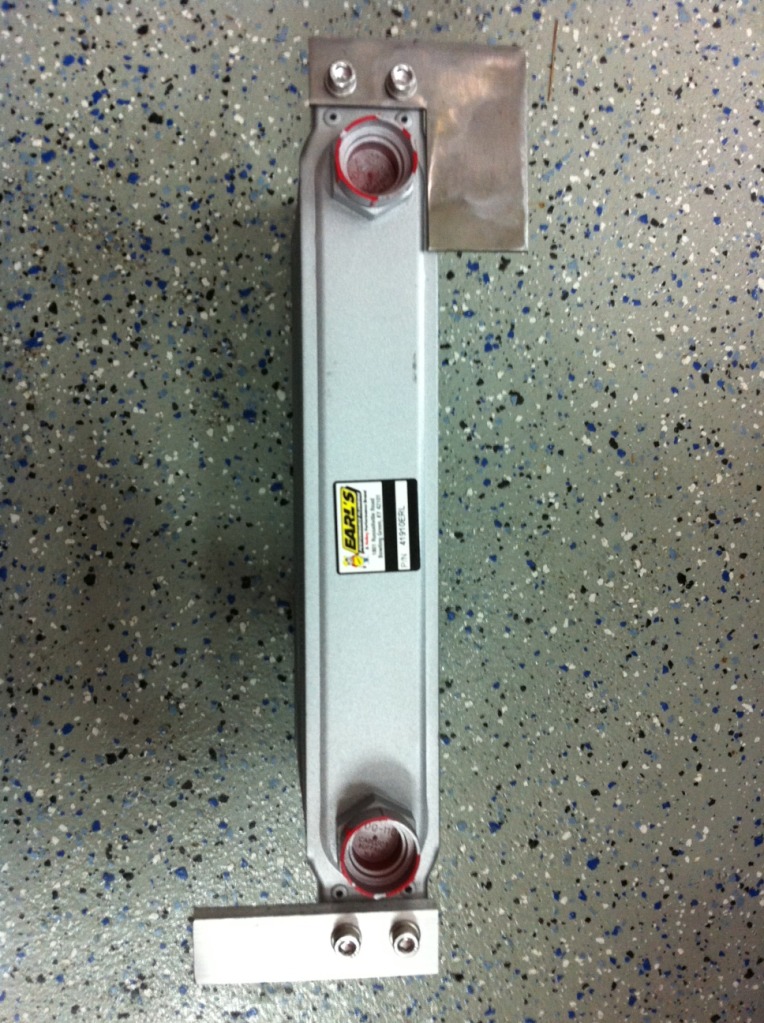
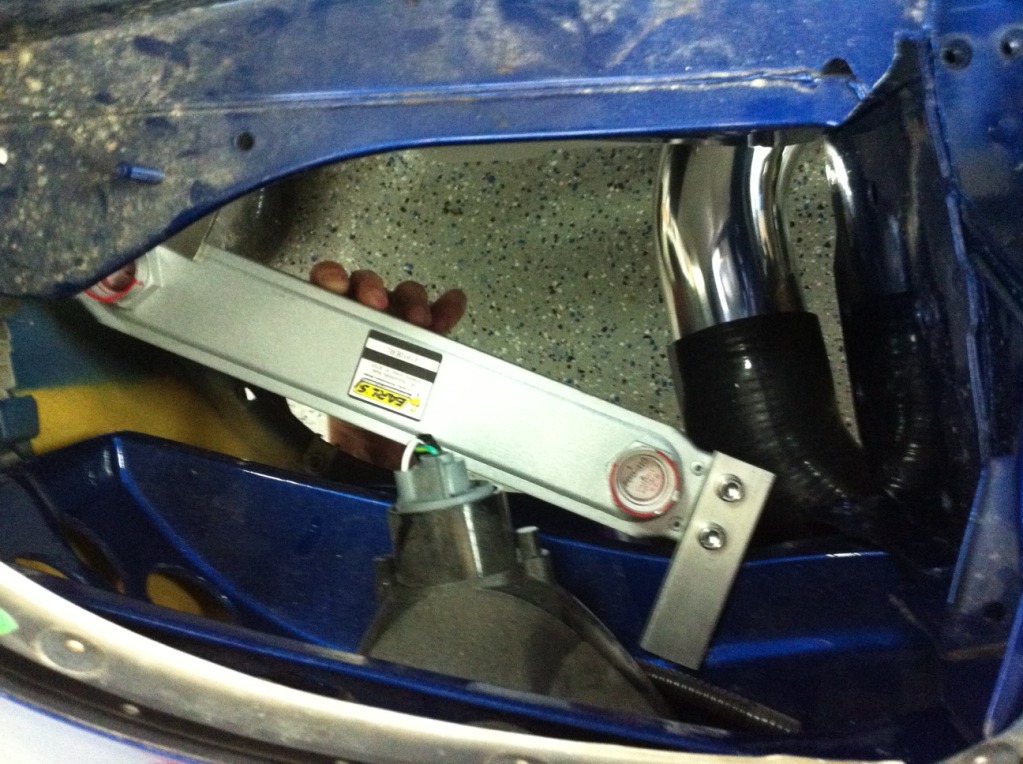
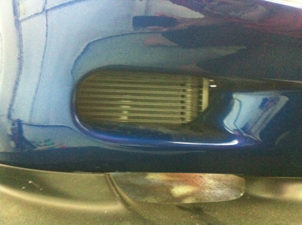
Made the brackets for the oil cooler today. I had to offset it slightly since the coupler from the intercooler took up some space. I had to trim the coupler .75" to get it to pull in tighter. Coverage across the opening is perect though. It covers it entirely. In the pics I'm just holding it in place so it's not level or anything. I'll be building some shrouding later once it's mounted. I didn't drill the holes in the body or bumper support yet for mounting as I'm going to wait until the turbo kit is done to make sure I don't have to re do the location. Other than a few holes drilled, it's done though.
06-04-12, 04:26 PM
#110
Well. My shrouding material gets here today so I'll do that next, but will need to get my nut serts from mcmaster carr before I can final install it. In other news, I test fitted the turbo again and it's looking like a lower mounted option is a no go... It's just too tight to be any good. I think with a TC series turbo, it's totally doable. The larger compressor housing on mine just requires too much angle to fit between the crank pulley and fan.
So, that means an upper mounted turbo, which means a high mounted downpipe in my case, which means ABS deletion. Which is really the only downside minus making the lower radiator hose somewhat of a pain in the *** potentially. So I'll be putting it somewhere close to where Blake put his and routing the downpipe similiarly. There are a lot of good things that come out of this though which makes the decision easy. (not like I really had a choice...)
Good things about doing it this way:
Low mount AC compressor (much better looking than on the head)
Factory location/style belt tensioner
Turbo drain is no longer a potential issue
More room below for crossover pipes
4" downpipe
Easily recirculated wastegate dump tubes
Perfect spot for catch can and surge tank where ABS used to be
Passenger manifolds much easier to build
I can sell my 96 spec ABS unit (best version of the 3 channel ABS before they upgraded to 99 spec 4 channel. PM me if interested.)
Turbo, downpipe and wastegates look cool up top.
So I'm going to pull my abs unit out and try and locate the turbo in its new home soon.
 06-08-12, 09:53 AM
#112
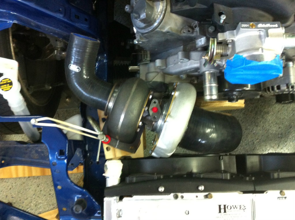
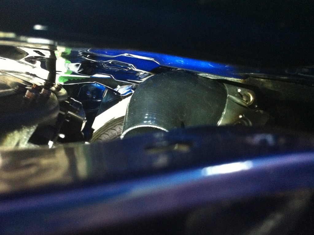
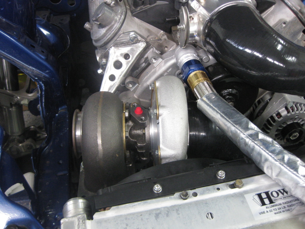
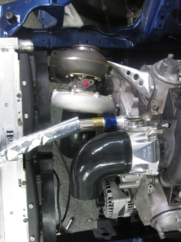
Here's what will probably be the position of the turbo. I'll probably angle the turbine inlet towards the back of the car for easy of crossover routing and to gain some room towards the front for radiator hose and hot side piping. But for now it serves it's purpose of giving me an idea of placement for building the manifolds. The passenger side will be much easier than it would have been which is nice. I also ordered a bunch of expensive *** AN fittings and hose so I can go ahead and establish those as fixed points.
I also got my new billet 90mm Holley throttle body in from Myboyblue. Looks way better to me than the Edelbrock and is more of a slimmer profile, and after some testing, it seems that there's a chance I might not have to cut the hood at all for it to fit. I'm ordering a 4"-3" 90 to test it out.
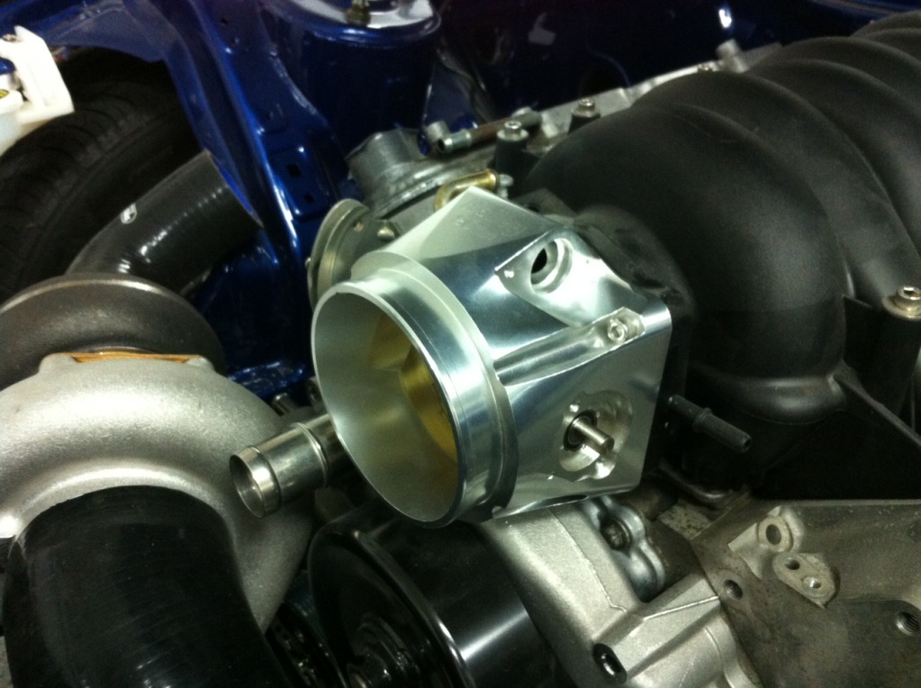
I also got my new billet 90mm Holley throttle body in from Myboyblue. Looks way better to me than the Edelbrock and is more of a slimmer profile, and after some testing, it seems that there's a chance I might not have to cut the hood at all for it to fit. I'm ordering a 4"-3" 90 to test it out.

 07-19-12, 12:13 PM
#116
Update time again.
I sold my Edelbrock throttle body to gnx7 and picked up a 90mm Holley from Myboyblue. It’s a lower profile design and with the 4”-3” 90 coupler it JUST clears the hood when closed. Like it couldn’t be closer. It’s just touching it ever so slightly but I think I’m going to cut off the under hood insulator in the area and call it good. I was pretty happy about that since I don’t have to cut the hood. The throttle body also looks badass since it’s all billet.

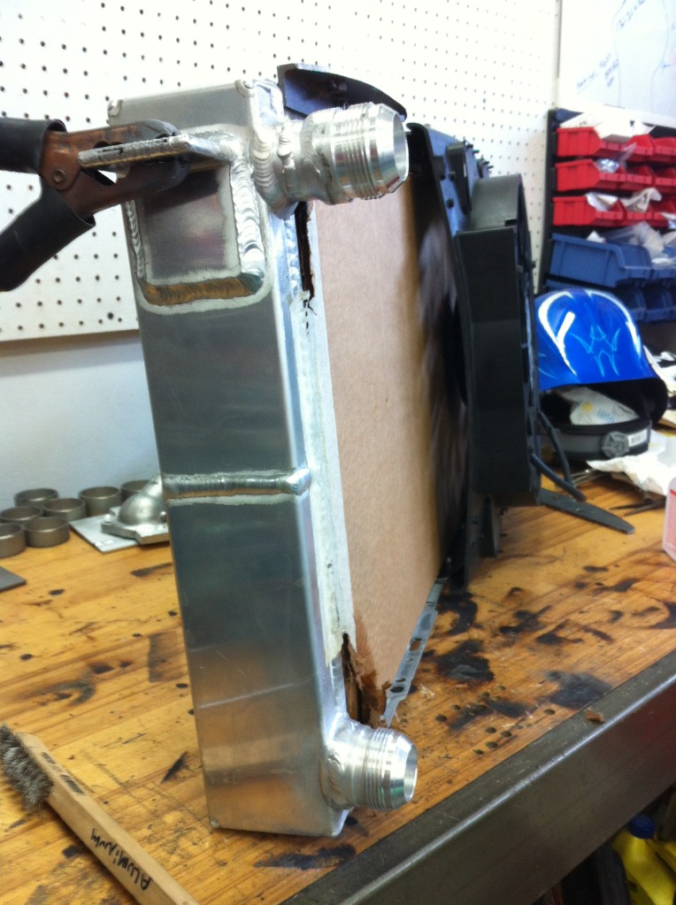
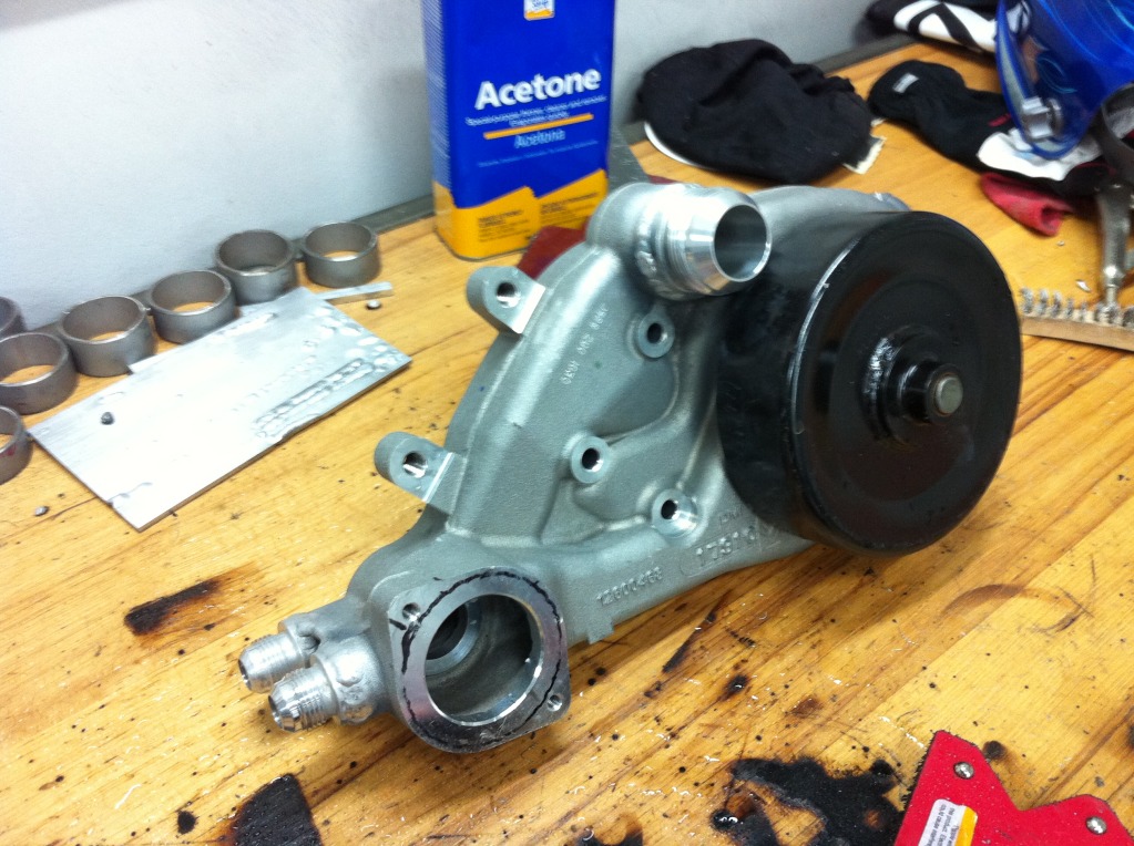
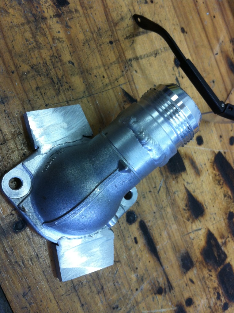
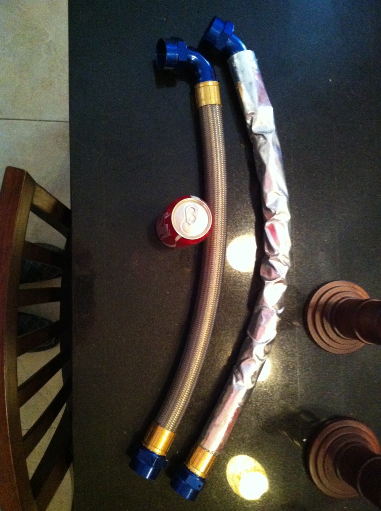
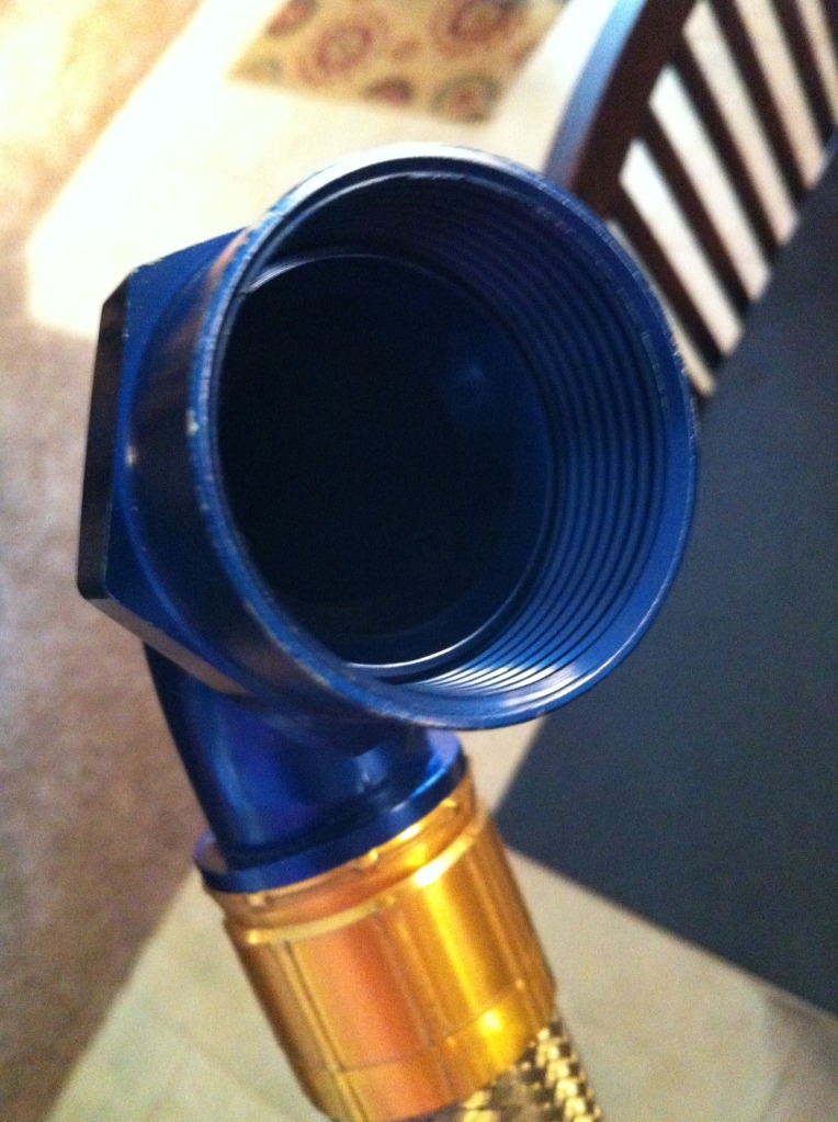
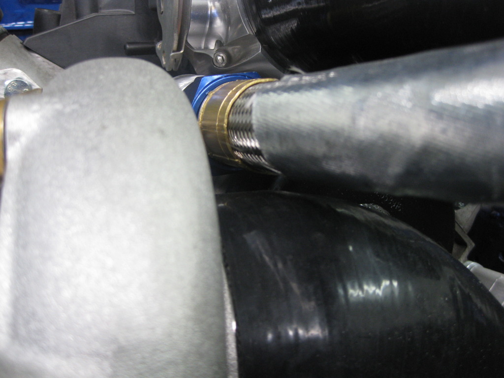
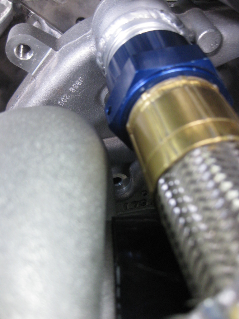
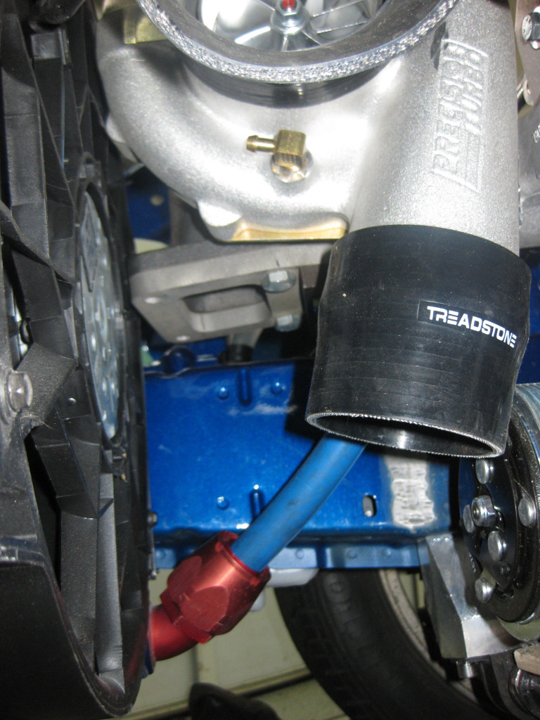
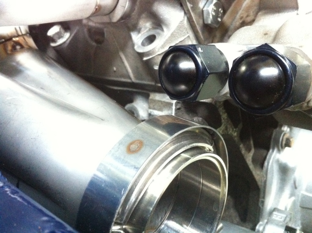
The next thing was welding on a bunch of AN fittings. After deciding to go for a top mounted turbo, I realized the -20AN extensions I had Howe weld onto the radiator weren’t needed, and actually got in the way… So I measured what was needed, cut em off and rewelded them back on. I also cut out the factory pressed in fittings from the water pump and welded a -20 fitting and 2 -8’s for the heater fore lines. I also cut off the nipple section from the factory thermostat housing and welded on a -20 fitting. I’m also going to be clocking it so I welded some 3/8” thick material where I’ll need the new holes to be. I’ll wait til everything is built to determine the final clocking position and clean up the tabs and such. I also got my new -20 BMRS radiator hoses. They’re sold as used but I doubt they were ever run on anything. They’re brand new.
I sold my Edelbrock throttle body to gnx7 and picked up a 90mm Holley from Myboyblue. It’s a lower profile design and with the 4”-3” 90 coupler it JUST clears the hood when closed. Like it couldn’t be closer. It’s just touching it ever so slightly but I think I’m going to cut off the under hood insulator in the area and call it good. I was pretty happy about that since I don’t have to cut the hood. The throttle body also looks badass since it’s all billet.
The next thing was welding on a bunch of AN fittings. After deciding to go for a top mounted turbo, I realized the -20AN extensions I had Howe weld onto the radiator weren’t needed, and actually got in the way… So I measured what was needed, cut em off and rewelded them back on. I also cut out the factory pressed in fittings from the water pump and welded a -20 fitting and 2 -8’s for the heater fore lines. I also cut off the nipple section from the factory thermostat housing and welded on a -20 fitting. I’m also going to be clocking it so I welded some 3/8” thick material where I’ll need the new holes to be. I’ll wait til everything is built to determine the final clocking position and clean up the tabs and such. I also got my new -20 BMRS radiator hoses. They’re sold as used but I doubt they were ever run on anything. They’re brand new.
07-19-12, 12:14 PM
#117
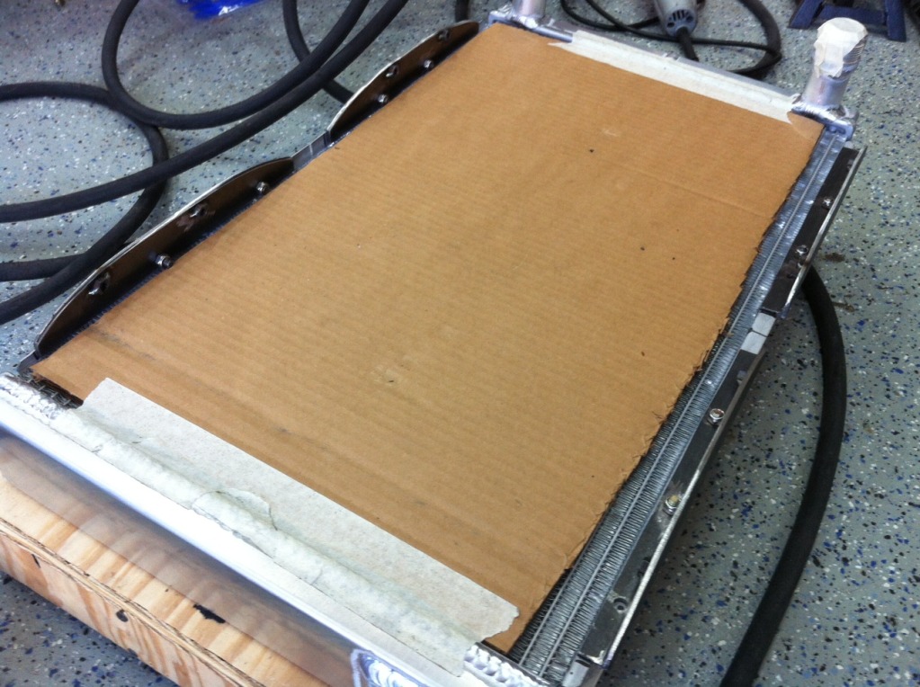
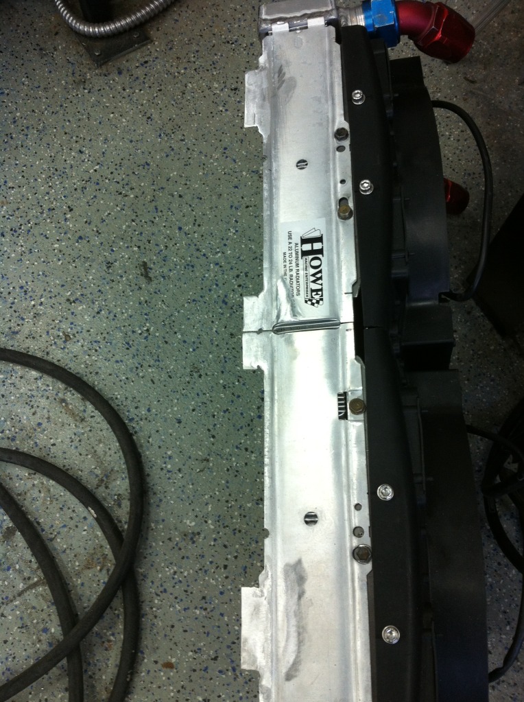
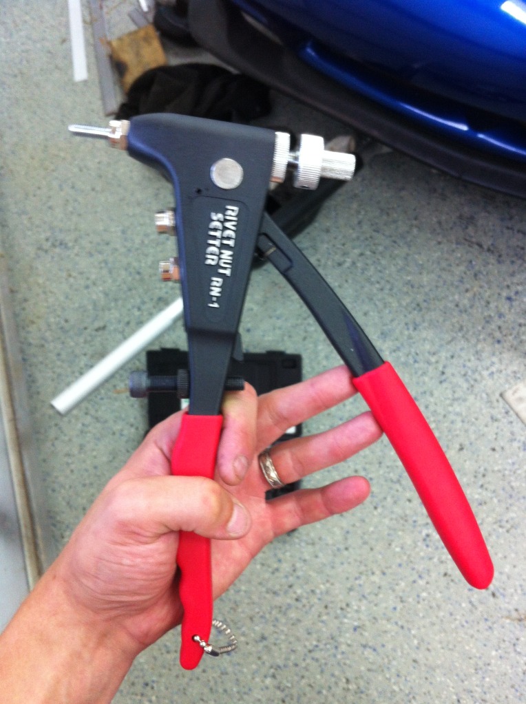
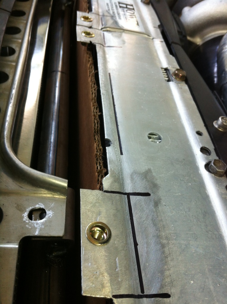
Next thing was shrouding. I bought a 30” sheet metal brake form Eastwood which I would recommend to anyone wanting a lower priced version that will do 16 gauge aluminum. The upper shroud also acts as the upper radiator mount and is made from 16 gauge aluminum. I bought a rivnut kit from mcmaster carr a while back and got to use it. I love this thing now. I had to weld some extension tabs onto the radiator and then rivnutted some 6mm nuts on there. Then I drilled some holes into by cross bar, welded some metal tabs to the cross bar, and then tapped them for 6mm- so when the bolt threads down through the tab, it just goes into the cross bar. Turned out perfect. I then made the side shrouding out of much thinner aluminum sheet since clearance is tight and it won’t be a structural piece. It bolts to the backside of the fan with a couple bolts that were already there, and then to the intercooler at some provided threaded bosses that were there. Once I do the lower shroud, it will be fully boxed in. I’m going to powdercoat the side shrouds black so they don’t stand out.
07-19-12, 12:15 PM
#118
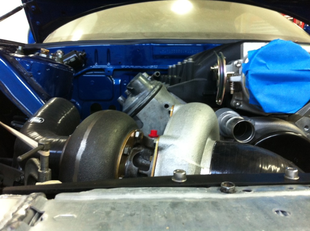
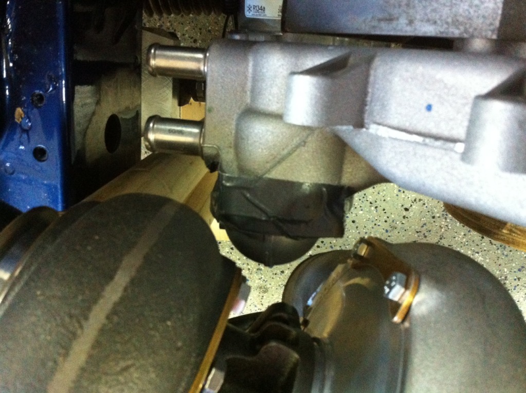
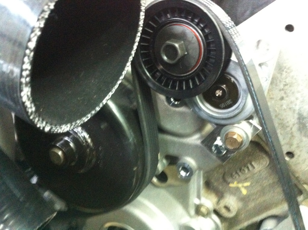
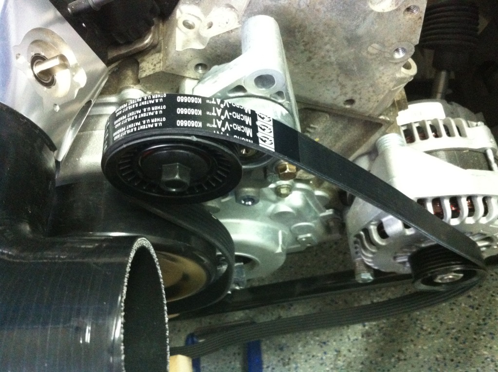
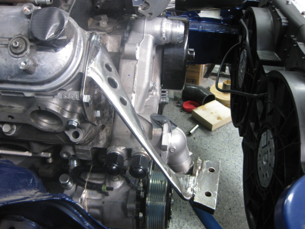
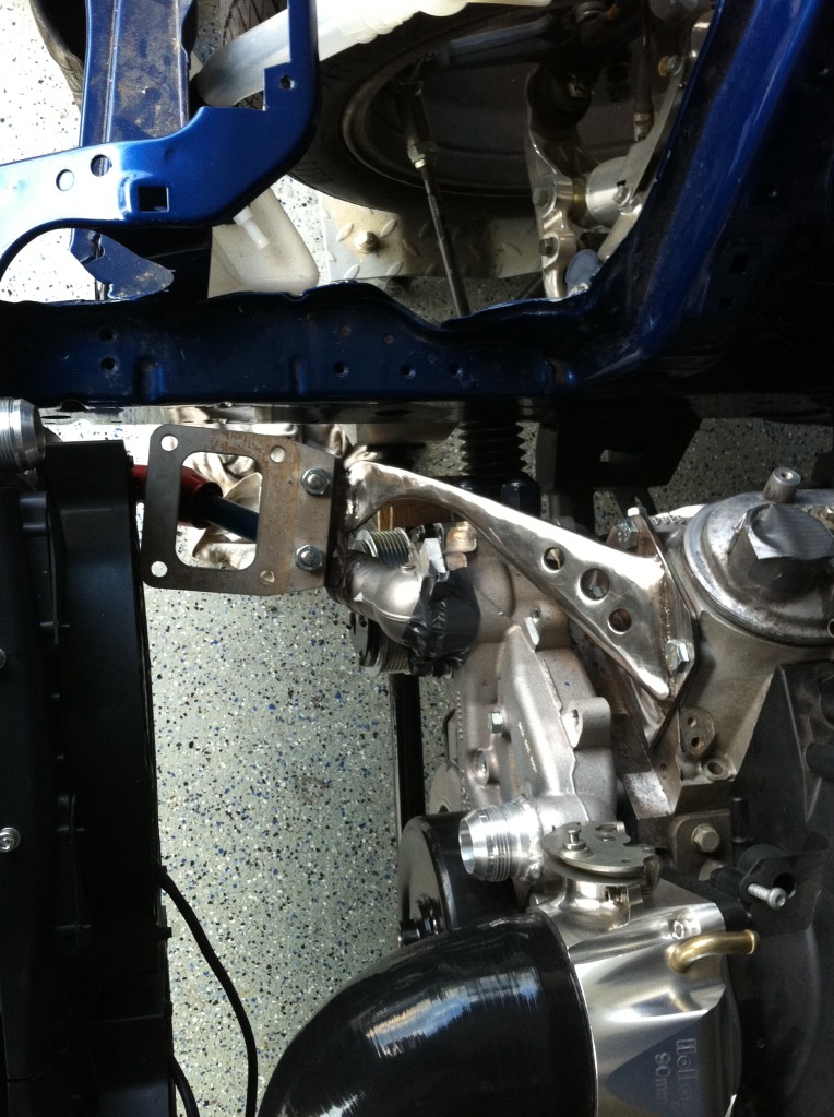
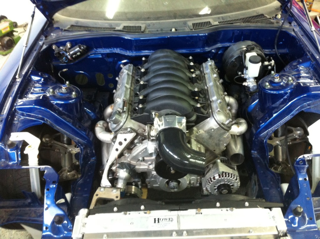
And the next thing was final mounting the turbo and making the turbo brace. I bought the same flange kit as Blake and it comes with a little �” thick bolt on piece that bolts to the T4 flange and then you can build whatever kind of brace off of that. I went and bought a factory accessory belt tensioner to see if it would fit in the factory spot and it would bolt up but there’s no way a belt is getting past the compressor housing. So that had me worried for a bit about how the belt would be routed, but then I think I figured out a nice solution. I just made a quick little bracket and bolted it to the water pump on the driver’s side really close to the throttle body. In the pics you can see a pretty close estimation of belt wrap. I think it will be plenty. I could always add an idler if I need to get some tension. I returned the factory one and will be getting a manual tension to use for real. I’ll deal with that later, I just wanted to have a general idea before I finalized anything. Then it was onto locating the turbo, which took a little bit since there are like 6 or 7 places where I have around 1/8”- 3/16” clearance. Then I made the turbo brace which was also tricky as the welding was causing it to move and I had 0 space for it to move. But I got it all straight and it came out perfect. It’s all 3/8” round bar and 3/16” plate. I made a hard C shaped main tube and then triangulated it with some more round bar, then supported everything with plate. I could stand on it. I smoothed it out as much as was needed. You’ll never see the lower part where the flange is and it will be powdercoated so it will all blend in nicely. I really like the way it looks. The turbo looks like it’s touching the fan but it’s not. Couldn’t be closer though. Haha.
 07-19-12, 12:16 PM
#120
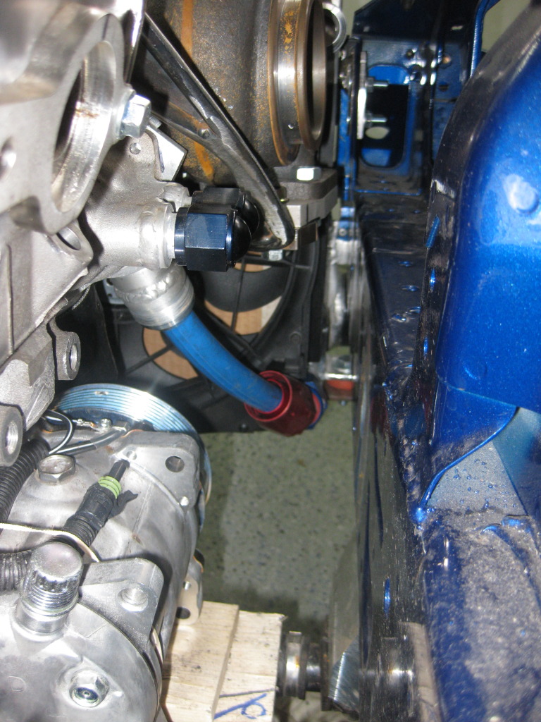
Here are a couple pics that show how I’m going to do the crossover pipes and everything in that region. The driver’s crossover will run right under the compressor housing next to the compressor outlet and over the lower radiator hose. The passenger’s will run right to the right of the lower radiator hose. Hot side intercooler pipe will run to the right of the lower radiator hose.
So. There that is. There have also been rumors that I’ve started on the manifolds already…
So. There that is. There have also been rumors that I’ve started on the manifolds already…
07-25-12, 05:22 PM
#121
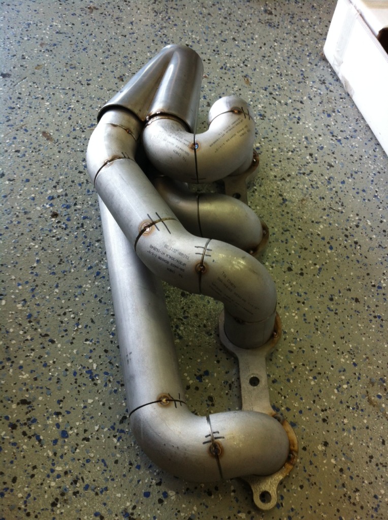
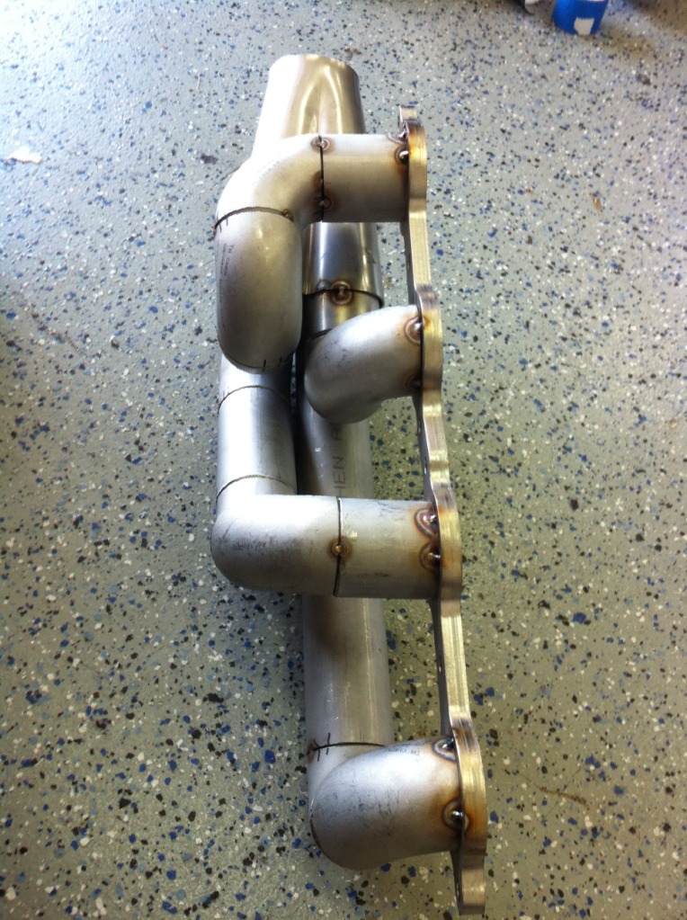
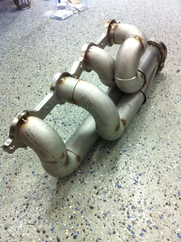
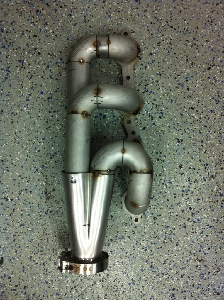
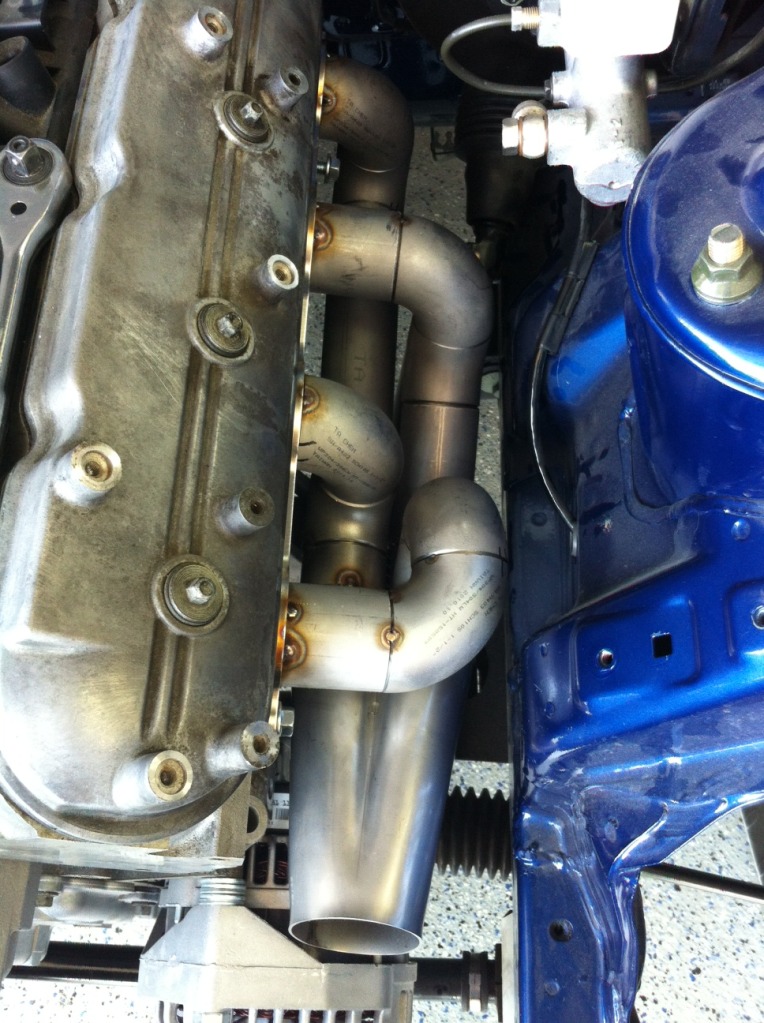
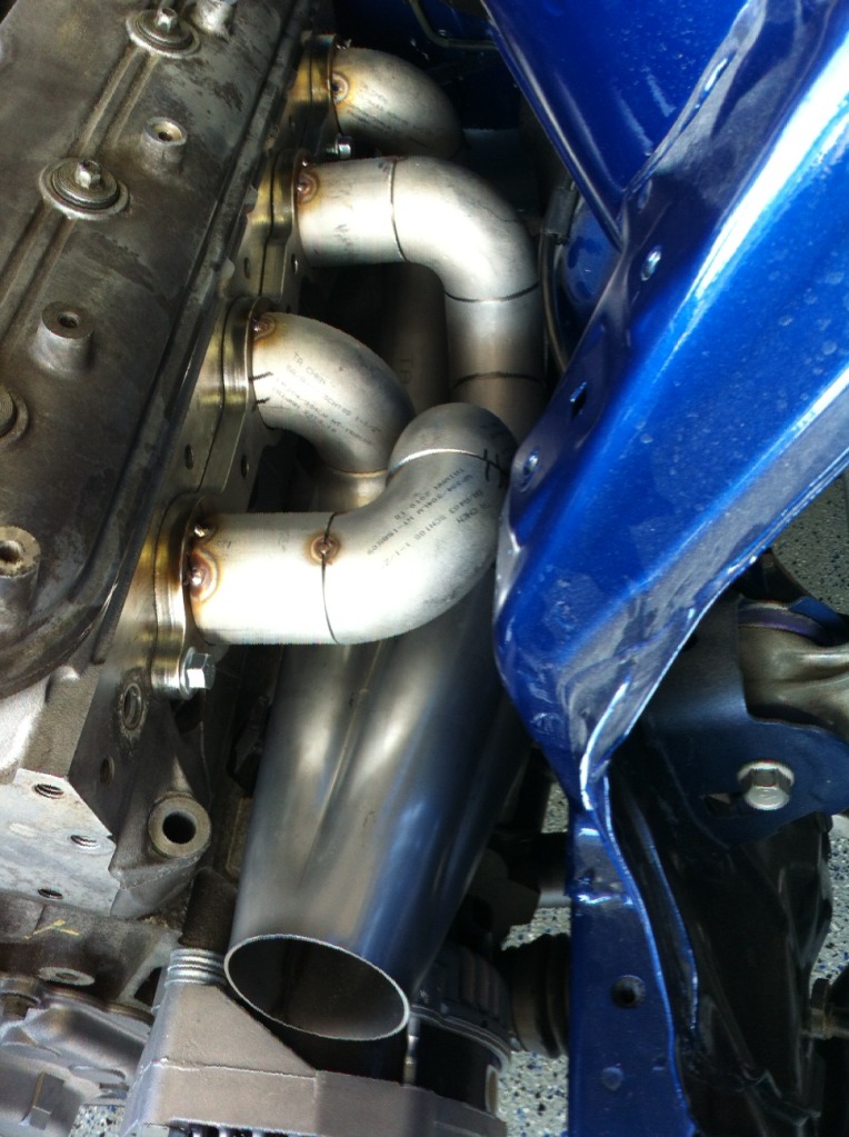
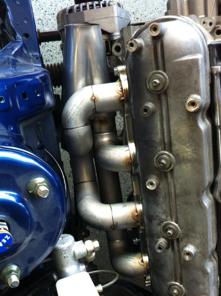
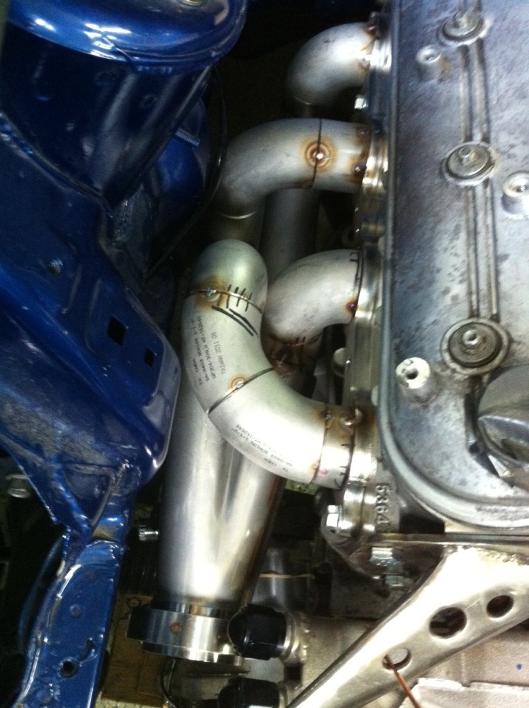
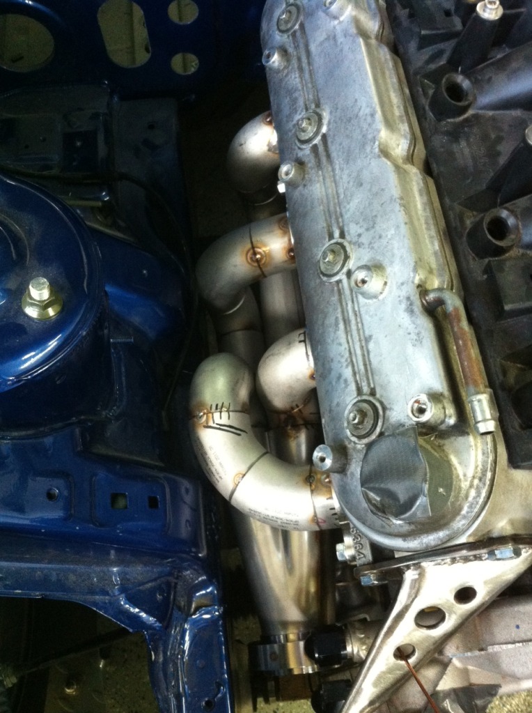
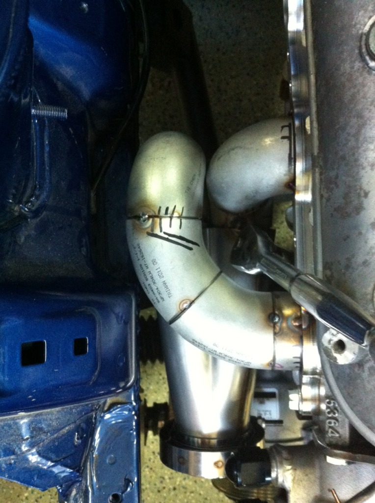
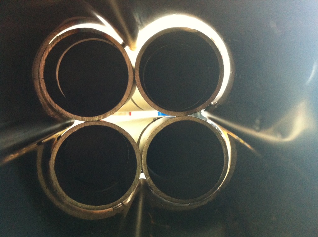
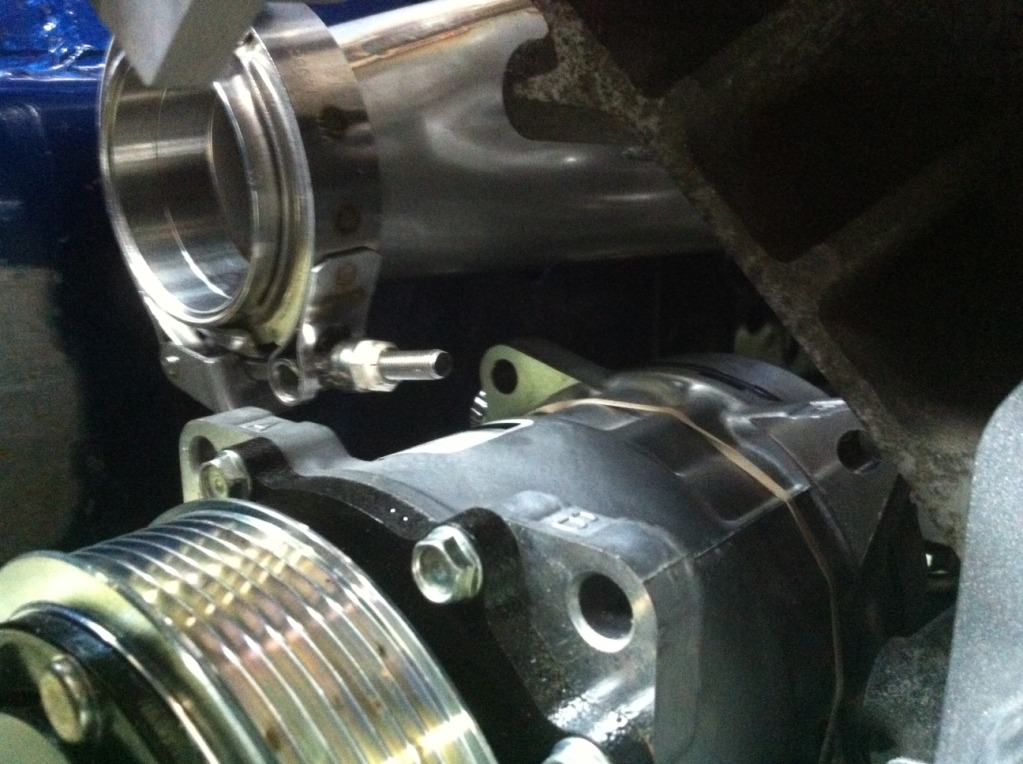
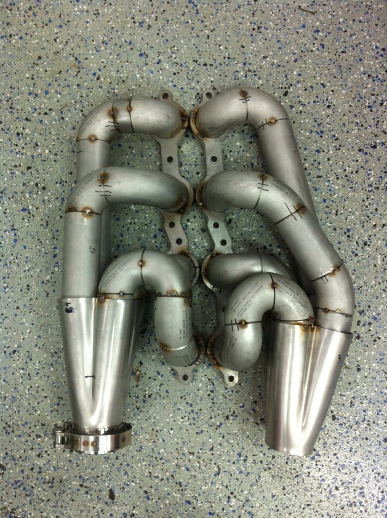
Well this didn't take long.  Was able to get both manifolds made and tacked up in about 3 days working on and off. Came together quicker than I thought it would. I also love Summit if I haven't made that clear. Ordered a couple vibrant 2.5" v bands Monday and they were here wednesday afternoon. It's always 2 day shipping with them. Love it. So these are schedule 10 304 stainless runners with 3/8" thick flanges and 1/16" collectors. It all came together really well on both sides, the passenger obviously being the tighet of the 2 sides. The plug access is perfect on all 8. That front plug on the passenger looks precarious but you can see in the halfway assembled pic that I've got the plug barely threaded in, with the spark plug socket attached to the socket. I can pull all of that out easily so that's all I'd ever need. I had to tack the v band flange to the passenger side so I could know how much room I really had. It's close but with plenty of room. I still have those stainless merge bullets to weld on after the runners get fully welded so I made sure that the entry of the runners was nice in relation to each other and the collector. I'm really happy with how they turned out. Just need to get them fully welded now and then build the crossovers. I think the next step for me is to build the mount for the AC compressor. Or possibly look into assembling the Kevin Doe strut bar materials I have and looking at the downpipe situation.
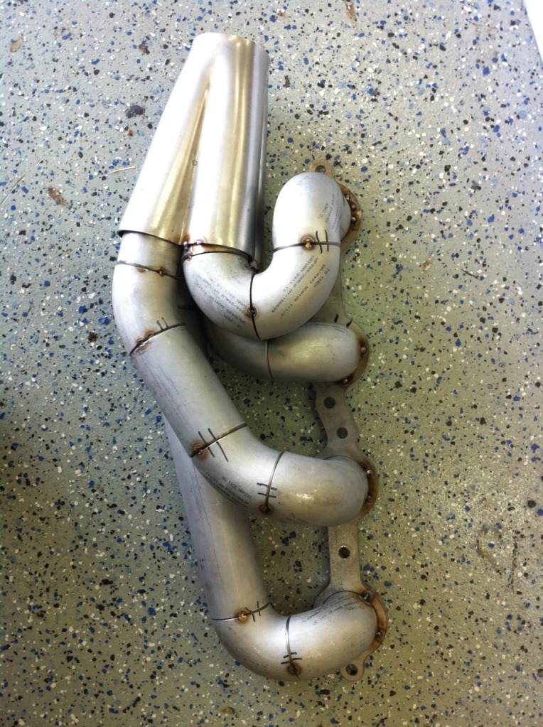
Was able to get both manifolds made and tacked up in about 3 days working on and off. Came together quicker than I thought it would. I also love Summit if I haven't made that clear. Ordered a couple vibrant 2.5" v bands Monday and they were here wednesday afternoon. It's always 2 day shipping with them. Love it. So these are schedule 10 304 stainless runners with 3/8" thick flanges and 1/16" collectors. It all came together really well on both sides, the passenger obviously being the tighet of the 2 sides. The plug access is perfect on all 8. That front plug on the passenger looks precarious but you can see in the halfway assembled pic that I've got the plug barely threaded in, with the spark plug socket attached to the socket. I can pull all of that out easily so that's all I'd ever need. I had to tack the v band flange to the passenger side so I could know how much room I really had. It's close but with plenty of room. I still have those stainless merge bullets to weld on after the runners get fully welded so I made sure that the entry of the runners was nice in relation to each other and the collector. I'm really happy with how they turned out. Just need to get them fully welded now and then build the crossovers. I think the next step for me is to build the mount for the AC compressor. Or possibly look into assembling the Kevin Doe strut bar materials I have and looking at the downpipe situation.
 07-26-12, 03:46 PM
#124
Wastegate John
iTrader: (13)
Join Date: Feb 2008
Location: Long Island NY 11746
Posts: 2,979
Likes: 0
Received 9 Likes
on
9 Posts
We dont want you here.... J/K
Where did you get the Rivet nut tool. I need one of those.
Although I do not like V8 FD's this build thread has some amazing fabrication and attention to detail. I just wish you could have showcased your talents using a rotary engine. Oh well.
Where did you get the Rivet nut tool. I need one of those.
Although I do not like V8 FD's this build thread has some amazing fabrication and attention to detail. I just wish you could have showcased your talents using a rotary engine. Oh well.