
A little progress...


What kinda turbos will you run Jim? I think I have a picture of a sema Chicayne that I'll try and post tomarrow with a V8 twin turbo setup, which was amazing to say the least.
What will the cost of the cradle be?
What will the cost of the cradle be?
Thread Starter
Super Snuggles
Joined: Feb 2001
Posts: 10,091
Likes: 34
From: Redmond, WA
Dunno, but I do know that there will only be one of them.
It sure is. I've met Troy, BTW, and Foose. My cousin knows them. Watch your step, don't trip over the pile of names I'm dropping. 
Dunno, but I do know that there will only be one of them... oops. Just kidding.
Still don't have word from my stick-metal-together guy if he's interested in making more, but chances are the new welding jig to make it happen is already done.
I think I have a picture of a sema Chicayne that I'll try and post tomarrow with a V8 twin turbo setup, which was amazing to say the least.
What will the cost of the cradle be?
Still don't have word from my stick-metal-together guy if he's interested in making more, but chances are the new welding jig to make it happen is already done.
Newb Photog
Joined: Jul 2001
Posts: 2,171
Likes: 0
From: new jersey
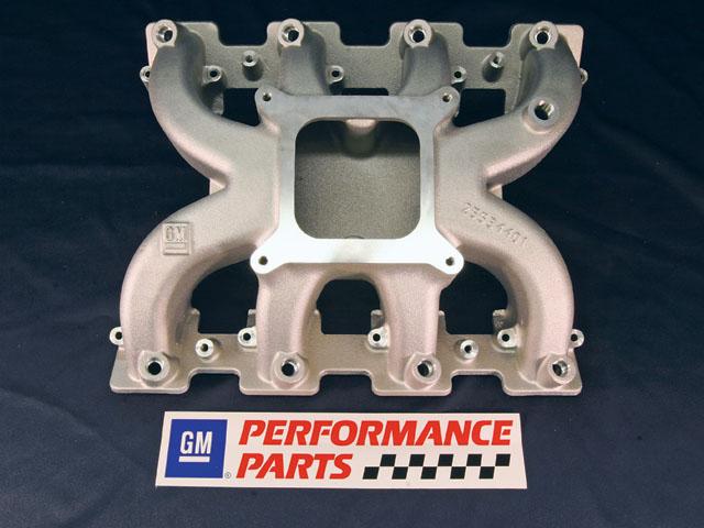
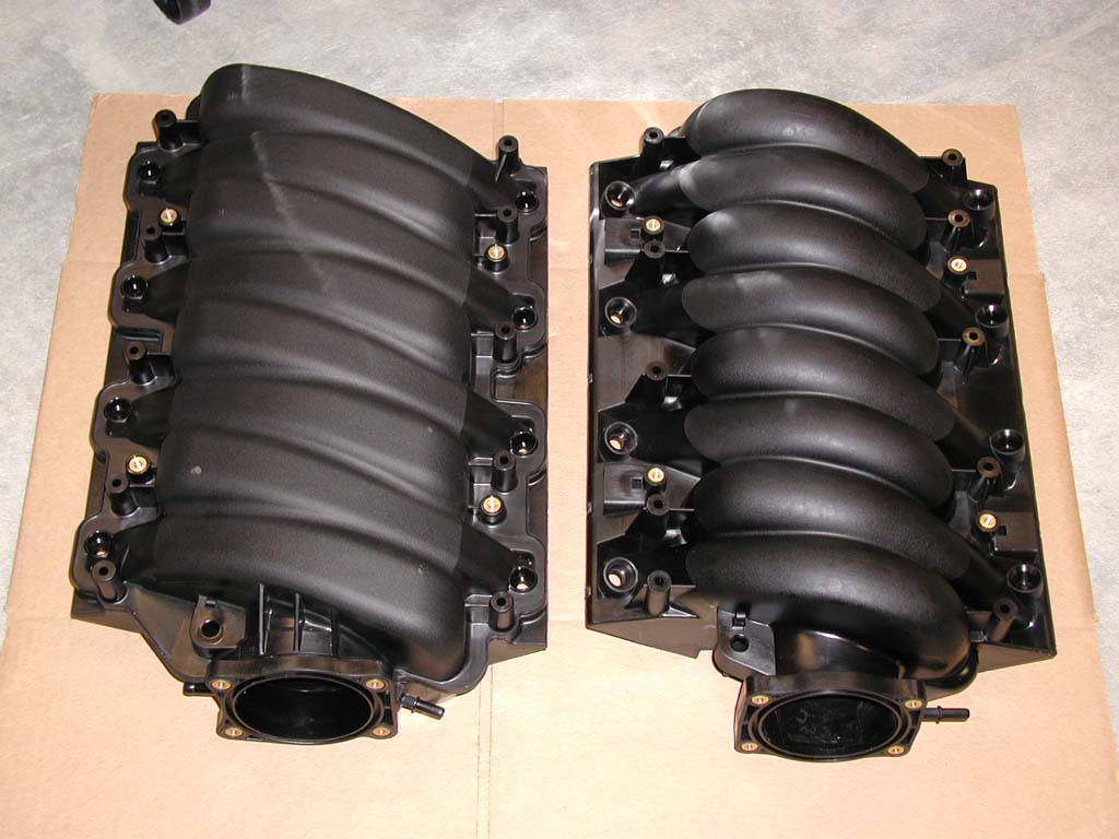
So now I'm considering replacing the center section of a GM L92 carb intake (shown below) with a box-style central plenum that doesn't extent past the rear-most intake runner. That would give me the room I need at the back of the intake, but it will also require a lot of custom work and mock-up and won't be readily repeatable.
I saw it today on Spike TV and got excited.
Edit: should have searched first: http://www.ls1tech.com/forums/showpo...17&postcount=2
Last edited by wptrx7; Jun 3, 2007 at 04:56 PM.
Rotary Enthusiast
Joined: Jan 2002
Posts: 859
Likes: 0
From: 15143
If you move the engine forward, the CG moves too. Too hard to visualize? Imagine what happens if the engine moves past the front axle line.


in the lower diagram, the sphere on the right would be appyling all of it's force (weight) perfectly downward, as with the rest of the spheres. however, this downward force would manifest itself as a moment (torque) tending to turn the sphere/pedestal system clockwise. assuming everything was hard mounted so that nothing could move in terms of its place and orientation on the whole configuration, this moment would be centered on the point where the pedestal is attached to the lever arm, causing the whole system to want to turn clockwise.
While it is not identical to being simply offset, the effect is similar.
To be clear, I tend to agree that at the miniscule difference in weight that has been proven with these swaps, to feel the difference would require quite the seasoned driver. it is CERTAINLY not beyond a very small amount of compensation on the part of any driver who is the caliber to notice such a difference anyway.
I severely disagree with this diagram as well. Its a pretty picture but it lacks any mathematical proof.
In rebuttal lets assume that the chassis is a lever(one of the simple machines). Your contention via diagram is that a weight's force and effect on center of gravity is dependent only on its anchored position on the lever.
Let me paint a mental scenario. Your picture represents the mass as a ball perched on a lever anchored to the primary lever via a traingle with a definite contact point. Imagine the system welded together as it would have to be without the rope, which turns out incosequential because it simply prevents the weight from tipping the secondary platform, or lever.
In this scenario, which more accurately represents an automobile(with the secondary lever as motor mounts and the primary lever as the front subframe). the secondary lever becomes an extension of the primary lever. the combination of the levers creates a greater amount of torque on the front side of the vehicle's frame(or lever) relative to the previous center of gravity.
In conclusion moving the engine farther forward in a vehicle moves the center of mass(center of gravity) farther forward regardless of any engine mount scenario. The defining aspect of center of gravity is the relationship of mass to a volume as opposed to its anchored point on a lever. The necessity of the rope in the diagram in and of itself debunks the entire theory by proving the effectiveness of the secondary lever.
Just to clarify, I posted the image simply as a tool for someone to use to explain how the CG had shifted. I did not imply that the diagram was correct.... I still have not made up my mind to be honest.
With that being said I have yet to hear a solid argument. Arguing that the level creates a tendency for the masses to shift horizontally says nothing about the way that the vertical forces behave. Horizontal forces are inconsequential to the CG if nothing can actually move.
The rope and anchor point are simply representative of the diff mount and PPF which hold the diff, trans and engine in more-or-less fixed horizontal positions.
Thread Starter
Super Snuggles
Joined: Feb 2001
Posts: 10,091
Likes: 34
From: Redmond, WA
No offense, but you'll have a hard time convincing me you're qualified to discuss anything.
I stand by my previous assertion and fail to find any contradictory argument, though you doubt me so.
Last edited by Narfle; Jun 7, 2007 at 10:00 PM.
Nor have I. Just wanted to bounce and idea.
I agree.
But think of the front subframe as a radius. A force(the mass of the ls1 x the acceleration of gravity) will have a greater mechanical advantage the larger Its radius from any giver point(the center of the wheelbase if that was advantageous...im no chassis tuner right jim?).
Even if the powerplant frame connects the the rear of the car. it would tend to lighten the rear of the car, not the front.
Im sorry if i came off blunt I just enjoy a good discussion.
The rope and anchor point are simply representative of the diff mount and PPF which hold the diff, trans and engine in more-or-less fixed horizontal positions.
But think of the front subframe as a radius. A force(the mass of the ls1 x the acceleration of gravity) will have a greater mechanical advantage the larger Its radius from any giver point(the center of the wheelbase if that was advantageous...im no chassis tuner right jim?).
Even if the powerplant frame connects the the rear of the car. it would tend to lighten the rear of the car, not the front.
Im sorry if i came off blunt I just enjoy a good discussion.
Thread Starter
Super Snuggles
Joined: Feb 2001
Posts: 10,091
Likes: 34
From: Redmond, WA


Junior Member
Joined: May 2004
Posts: 10
Likes: 0
From: los angeles
Back on topic with a few comments/questions:
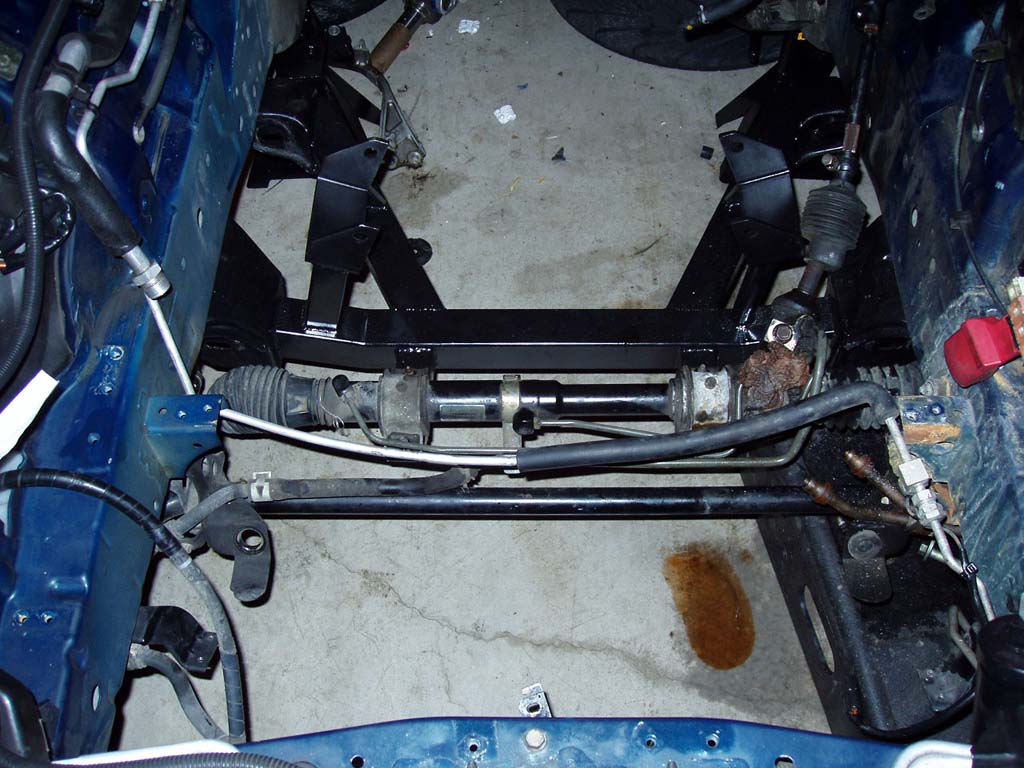
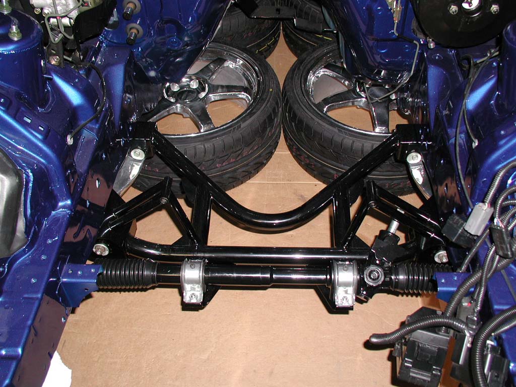
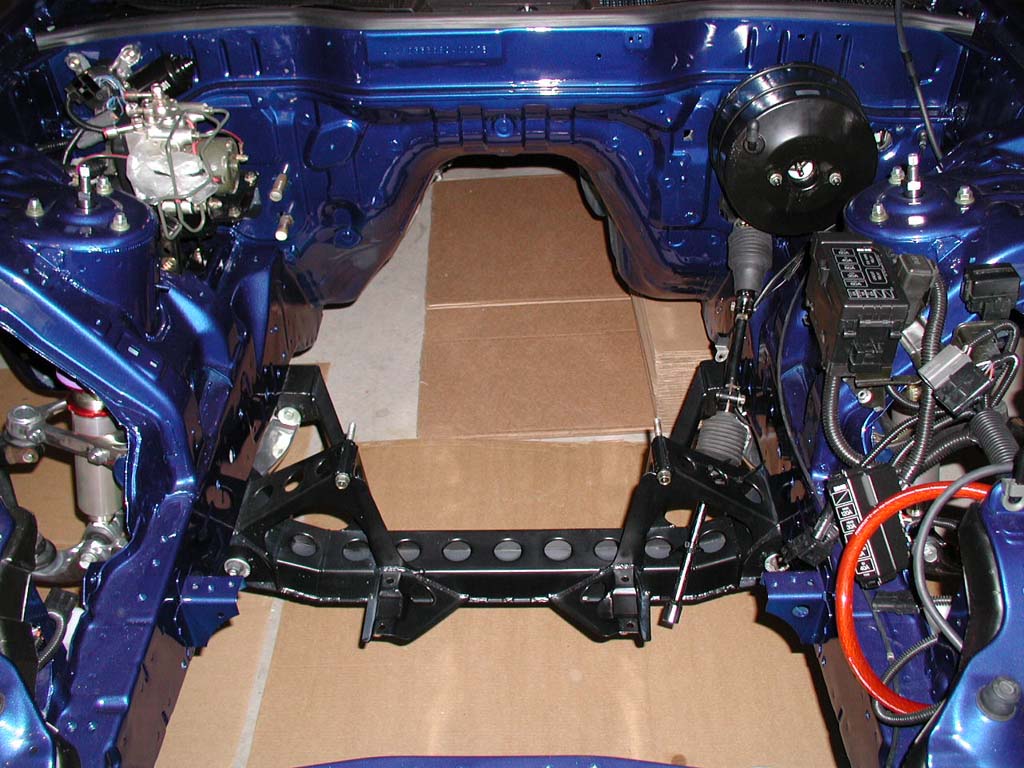
The new sub-frame looks good Jim. It appears to be an elegantly simple and stout design. Could you comment on the engine and steering rack placement with your new sub-frame compared to stock/ Hinson's. Also, you stated previously that it should accommodate the earlier LS1-6 series blocks correct?
Would you happen to know the height differences between the LS2/7 versus the LS1/6 with the LS6 intake?
I like that you've incorporated the Corvette/GTO mounts which are an all-around better design than the clam shells.
I'm assuming that you are still waiting for the final thumbs-up on the cradle before you address the bump steer correction. I'd be curious to see whether the tie rod end extensions/shimming will accommodate 17" wheels.
All around good work.
Rob
also does anyone have a comparo pic or pics of the jimlab vs hinson subframes? i actually came across this thread searching for pictures of how the hinson subframe locates things in relation to the steering rack but it appears most obviously that the jimlab design is better.
Junior Member
Joined: May 2004
Posts: 10
Likes: 0
From: los angeles
I severely disagree with this diagram as well. Its a pretty picture but it lacks any mathematical proof.
In rebuttal lets assume that the chassis is a lever(one of the simple machines). Your contention via diagram is that a weight's force and effect on center of gravity is dependent only on its anchored position on the lever.
Let me paint a mental scenario. Your picture represents the mass as a ball perched on a lever anchored to the primary lever via a traingle with a definite contact point. Imagine the system welded together as it would have to be without the rope, which turns out incosequential because it simply prevents the weight from tipping the secondary platform, or lever.
In this scenario, which more accurately represents an automobile(with the secondary lever as motor mounts and the primary lever as the front subframe). the secondary lever becomes an extension of the primary lever. the combination of the levers creates a greater amount of torque on the front side of the vehicle's frame(or lever) relative to the previous center of gravity.
In conclusion moving the engine farther forward in a vehicle moves the center of mass(center of gravity) farther forward regardless of any engine mount scenario. The defining aspect of center of gravity is the relationship of mass to a volume as opposed to its anchored point on a lever. The necessity of the rope in the diagram in and of itself debunks the entire theory by proving the effectiveness of the secondary lever.
In rebuttal lets assume that the chassis is a lever(one of the simple machines). Your contention via diagram is that a weight's force and effect on center of gravity is dependent only on its anchored position on the lever.
Let me paint a mental scenario. Your picture represents the mass as a ball perched on a lever anchored to the primary lever via a traingle with a definite contact point. Imagine the system welded together as it would have to be without the rope, which turns out incosequential because it simply prevents the weight from tipping the secondary platform, or lever.
In this scenario, which more accurately represents an automobile(with the secondary lever as motor mounts and the primary lever as the front subframe). the secondary lever becomes an extension of the primary lever. the combination of the levers creates a greater amount of torque on the front side of the vehicle's frame(or lever) relative to the previous center of gravity.
In conclusion moving the engine farther forward in a vehicle moves the center of mass(center of gravity) farther forward regardless of any engine mount scenario. The defining aspect of center of gravity is the relationship of mass to a volume as opposed to its anchored point on a lever. The necessity of the rope in the diagram in and of itself debunks the entire theory by proving the effectiveness of the secondary lever.
as long as the height of the motor remains unchanged (and it isn't because you're using the same subframe right? and it has the same level mounting holes) the cg as defined by what cg is not changed. cg is defined in terms of distance from the ground and distance from the roll center. this doesn't change with transverse movements.
what will change is the polar moment of inertia and the weight distribution which is what i think everyone is trippin' about. the diagram is incorrect in the sense that it looks like a seesaw and people are sayin' that the seesaw would be unbalanced if you shifted one of the weights outward... while this is true it's not anything to do with the real question at hand.
Thread Starter
Super Snuggles
Joined: Feb 2001
Posts: 10,091
Likes: 34
From: Redmond, WA
the hinson kit has apparently gotten some heat for this?
also does anyone have a comparo pic or pics of the jimlab vs hinson subframes?
My cradle (which is a complete replacement and doesn't require a core) looks like this (LT1 version shown, LSx is similar). Big difference in workmanship and quality.
And just for laughs, here's Granny's cradle. No core required, but you'll have to figure out how to compensate for the engine hitting the hood.
Last edited by jimlab; Jun 8, 2007 at 04:21 PM.
Junior Member
Joined: May 2004
Posts: 10
Likes: 0
From: los angeles
Can this be used in a fuel injection set up? How tall is this?
I saw it today on Spike TV and got excited.
Edit: should have searched first: http://www.ls1tech.com/forums/showpo...17&postcount=2
I saw it today on Spike TV and got excited.
Edit: should have searched first: http://www.ls1tech.com/forums/showpo...17&postcount=2
so has jim put this on and confirmed it'll back into the firewal nicely?
Thread Starter
Super Snuggles
Joined: Feb 2001
Posts: 10,091
Likes: 34
From: Redmond, WA
They're inteded for fuel inection. Too large for nitrous nozzles.
Look at the position of the rear intake runners compared to the LS7 and L76 intakes below, and note the position of the rear-most bolt towers in relation to the runners. Plenty of room.
so has jim put this on and confirmed it'll back into the firewall nicely?