
Fitting 315s on stock body FD

Fitting 315s on stock body FD
I posted this on another forum, but I figured it not specific to drivetrain so I'll post it over here as well, so all the FD guys can see what I've been up to.
Not all of this information is the most recent, as my plans progressed as I went forward. You can see the progession if you read through. Well here it is.
I want to fit Hoosier 315s, but the tire has to stay within the quarter panel. My tire tucks way up behind the quarter on full compression, so I can't have them poking out the sides like you can with some cars. Plus, I want the body to be stock. I have rolled fenders now, and I don't mind rolling them a bit more, and I’ll fold them flat if I can do so w/o making the quarters look wavy, and I certainly don't want to pull them. I did some pretty detailed clearance measuring with my current wheels. I measured at full suspension extension, full suspension compression, and in the middle of the two. It looks like a few things are necessary.
1. Custom rear sway bar end links from rod ends. I have since changed my mind on this, since I don’t run a rear sway bar right now. If I do, I'll have to rework the end links and go with a custom setup.
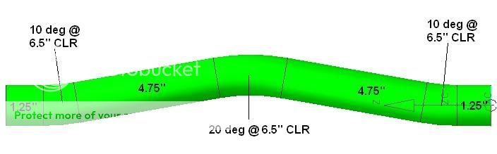
2. A custom made trailing arm of some sort. I had originally planned on making trailing arms with a "kink" in them. Basically I need to add 3/4" jog in the trailing arm to give the wheel/tire clearance. Was planning on using a 30,000 lb rod end, and 1 3/8" chrome moly tubing (0.095" wall). A jog in the tubing is generally a bad idea, but 3/4" offset isn't much, and I had a friend run an Ansys simulation using the 30,000 lb loading in both compression and tension. I have since scrapped this idea. The new idea is to offset the front trailing arm mount inboard. I have completed these, so I checked it off my list.
3. Massage a few locations on the metal inner fender to make room for a higher offset wheel.
Here are some pics of what I thougth the trailing arm would look like, before I killed that idea. I'm glad I talked myself out of that.


Then redesigned it to look like this:
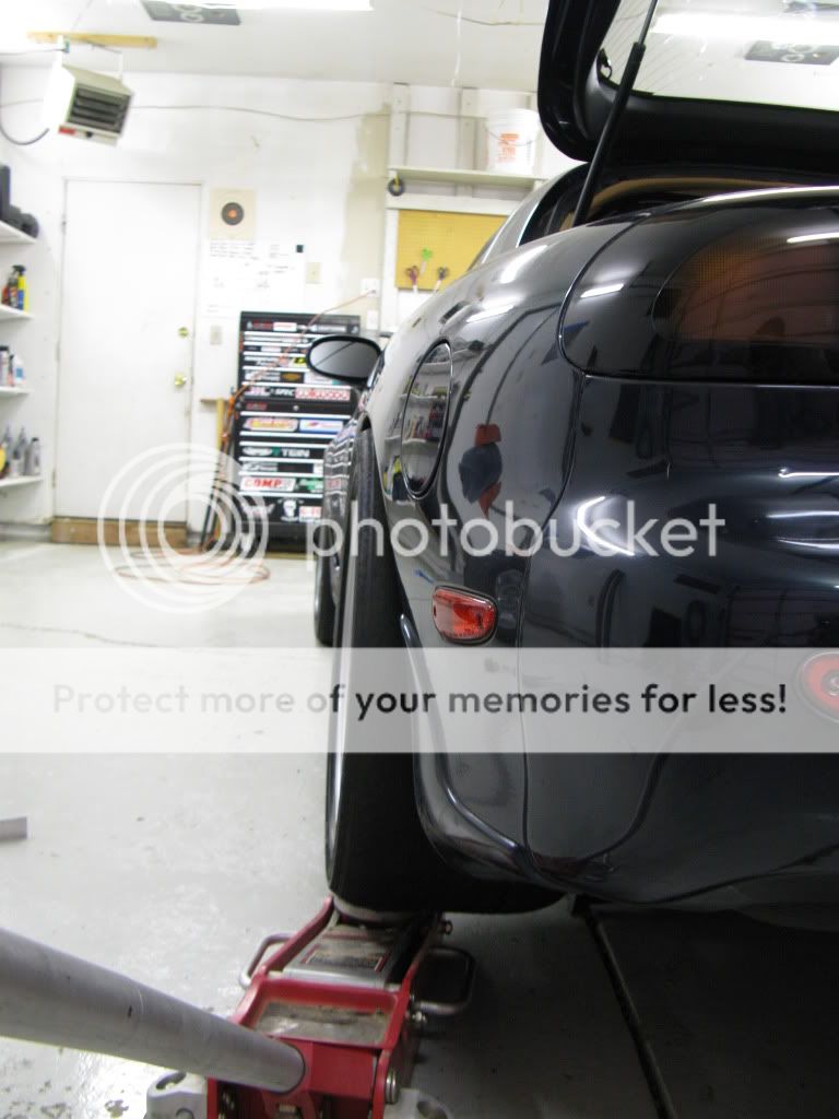
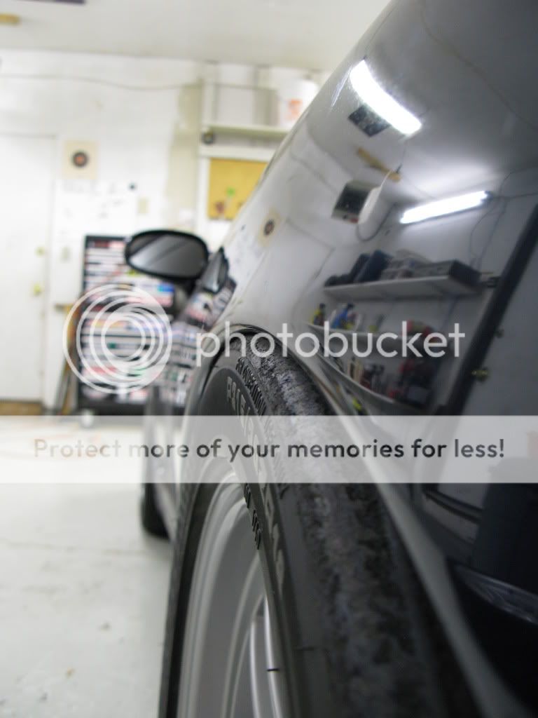
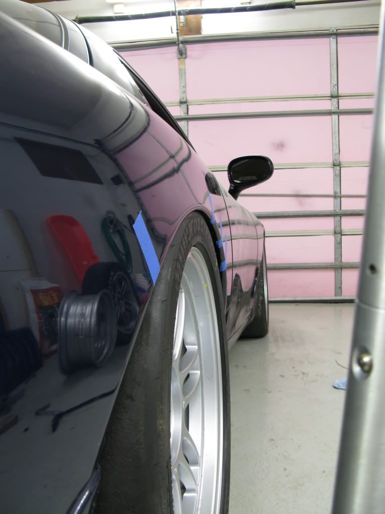
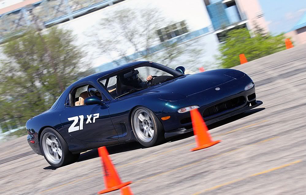
So here is kinda where I stand. I got some more Enkei RPF1s, they're 18x10 +38, which ends up very close to a 7" backspacing. I went ahead and mounted two different tires on them. I mounted a 315/30/18 A6 on one of them, and a 305/30/18 V710 on the other. I didn't expect the 315 to fit right, but I wanted to see how close it was, so I could figure out how much I needed to widen them. The tire is a bit bulgy on the wheel. The wheel will definitely have to be widened. The sidewall was so bulgy it wouldn't tuck under the quarter pannel lip. I'll have to roll the lip more for sure as well. I think that with the wheel widened it will pull in the sidewall and barely clear the lip. I also mounted that 305, and tested fitted that. The 305 fit the 10" wheel very well, and that cleared the quarter pannel lip. So, I figured out how much I needed to widen the 10" to make the 315 fit like the 305. It turned out to be 3/4" wider and will fit. So, looks like only two things will have to happen to get it to fit right. Roll the fender lip a bit more. I checked all the clearances with clay. I should have some more work done hopefully later this week with more pics after the wheels are widened. Here are some pics. Here is it with the 315 at ride height, or close to it. I removed my springs from the coilovers so I could move the suspension easily.
[img width=775 height=581]http://i93.photobucket.com/albums/l55/Kevin_Doe/RX-7/Fitting315s.jpg[/img]
You can see how the sidewall is a bit overhanging the wheel, and how it sticks out a bit past the body lines.

Here is a picture comparing the 275 Hoosier on a 17x9.5", a 305 V710 on a 18x10" and a 315 A6 on a 18x10". The 275 koni challenge tire and the V710 are pretty much the same size, maybe 3/16" difference at the very most. The 315 A6 is much wider.
[img width=775 height=581]http://i93.photobucket.com/albums/l55/Kevin_Doe/RX-7/Fitting315s5.jpg[/img]
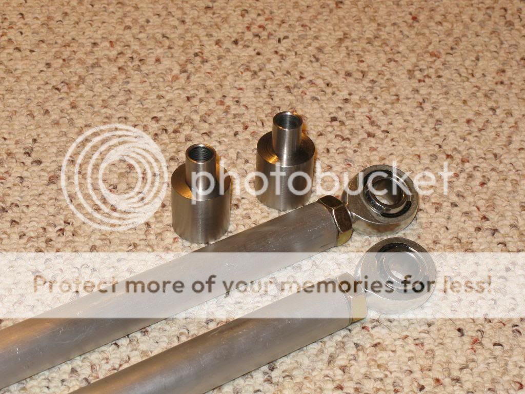
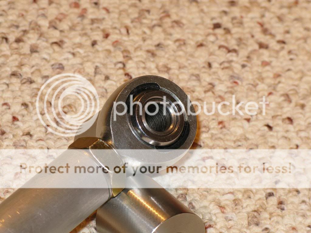
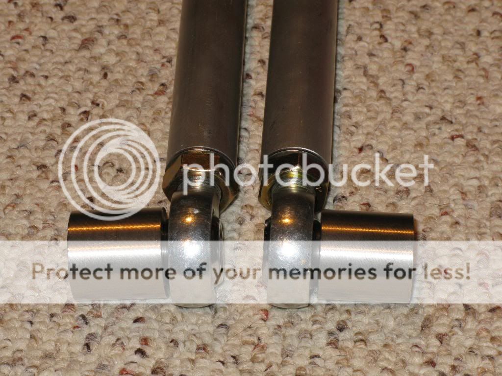
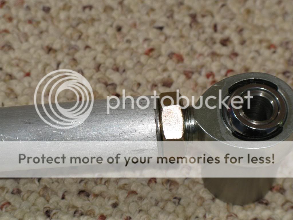
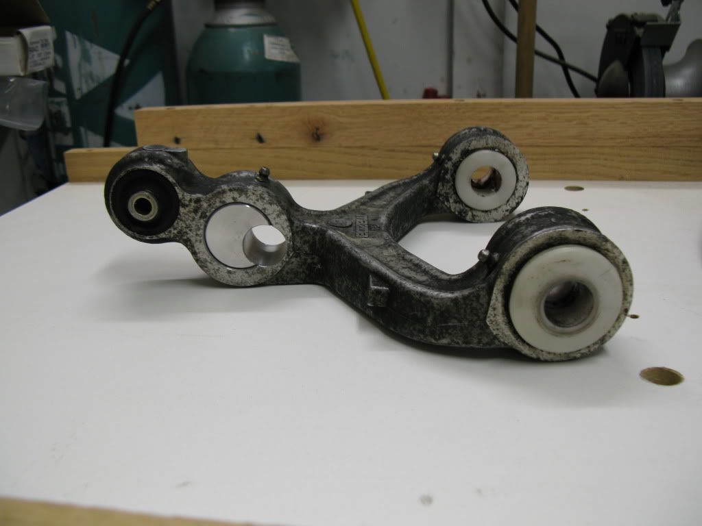
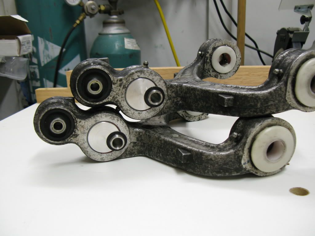
I was able to finish up my trailing arms today. Here they are. Did I mention that I'm glad I didn't go with those curved ones?
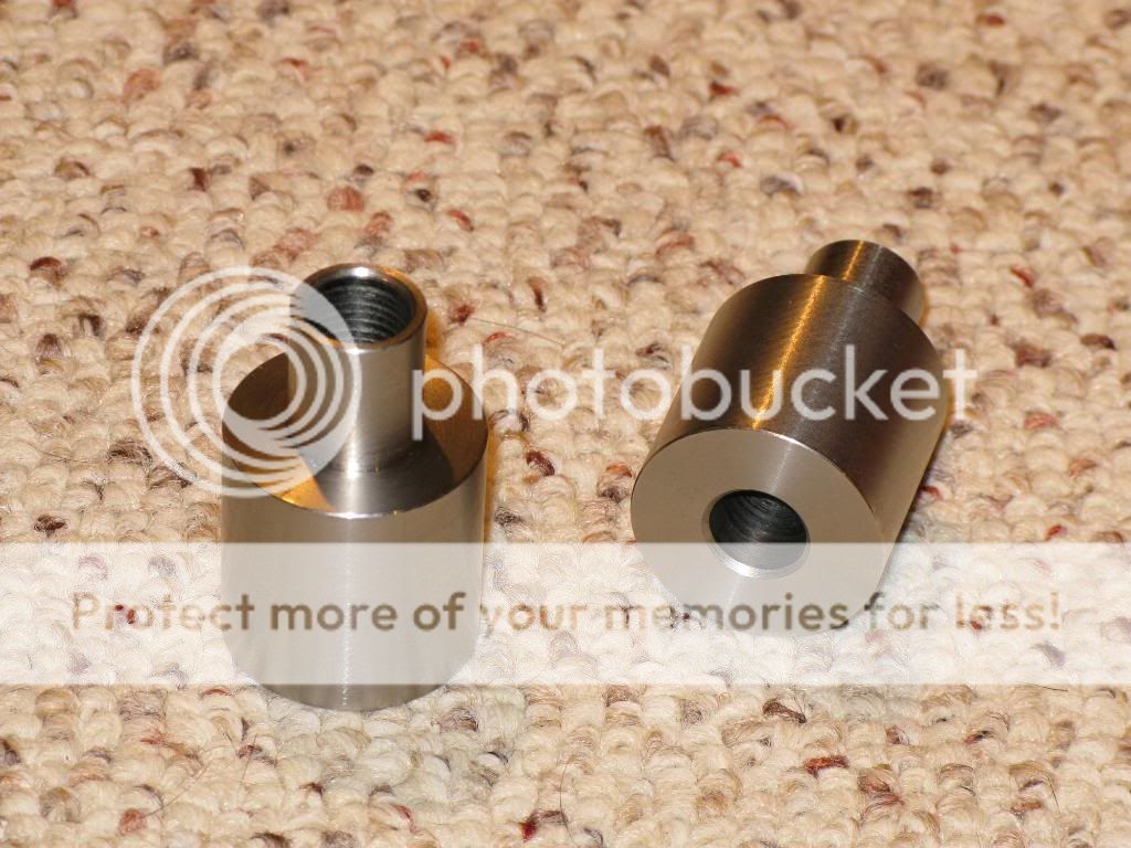
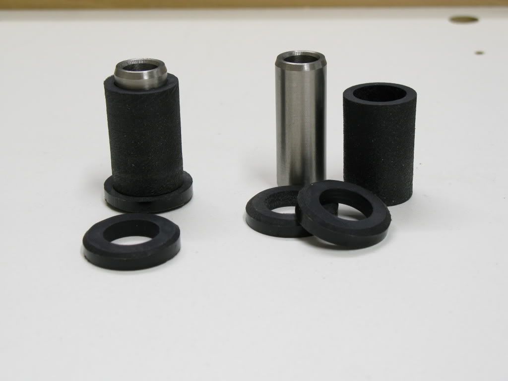
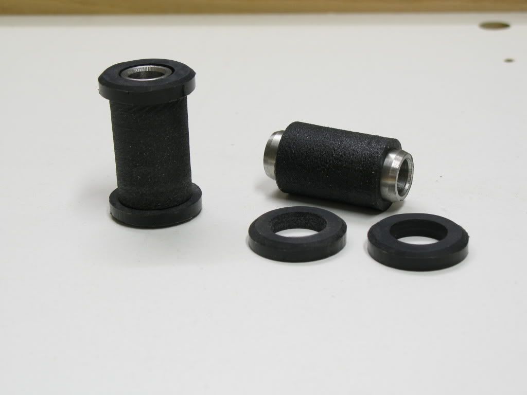
They're 6061-T6 aluminum for the rods. The rod ends are self sealing, self lubricating, 18,000 lb chromoly pieces. I have hardened 17-7 stainless steel washers between the jam nut and the aluminum rod, and the other end. The spacers I made are from 304 stainless steel. The clearance between the rod end ID and spacer OD are 0.005" and the clearance between the spacer ID and the bolt shank is 0.005". Its a very snug fit, and nearly no slop. Any tighter fit and I'd be worried that something might get stuck together once clamped down tight. The bushing part of the spacer is 0.030" shorter than the thickness of the rod end ball. This is to make sure that the rod end is clamped tight and not bottoming out on the bushing shoulder.
I did some calculations (and FBDs) based on the suspension geometry and the max torque my car made. If the tires hook in 1st gear, at peak torque would be the peak loading in the trailing arm (other than shock loading). Based upon making 435 ft-lbs of torque, and my gear ratios, that means there will be 5297 ft-lbs of torque at the axle in 1st gear. From my measurements the upper control arm mount on the knuckle is 6.25" higher than the hub center, and the trailing arm mount is 4.75" lower than the hub center. Using that I got a forward force on the hub center to be 4966 lbs, which is divided between the upper control arm and trailing arm. The upper control arm will take 2144 lbs, and the trailing arm will take 2822 lbs in the forward direction. That puts the trailing arm in compression on acceleration, and tension in deceleration.
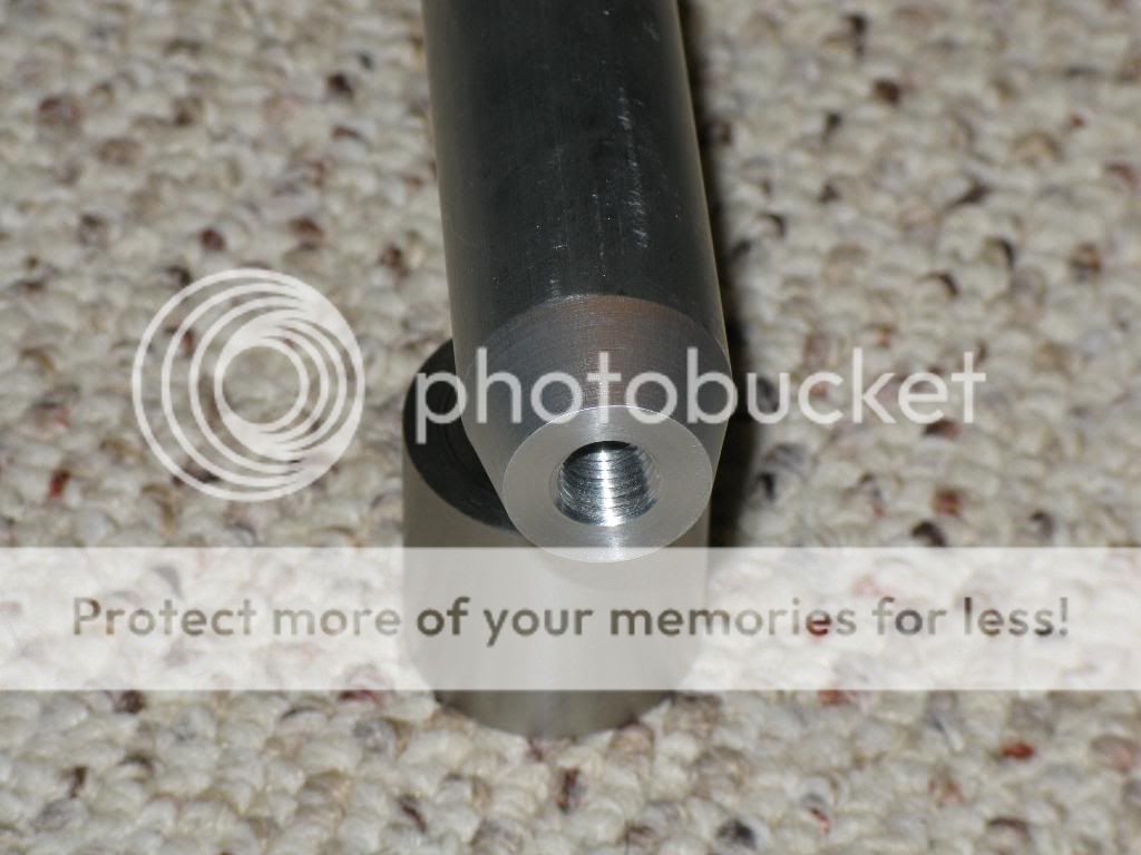
The smallest cross sectional area of my trailing arm is 0.478 sqin, which is located at the rod end, where its drilled and tapped for 5/8"x18 threads. Using the 6061-T6s yield strength of 40,000 psi, I thought the weakest link of my trailing arms may be the section where its drilled and tapped for the rod end, but that section can support 19,120 lbs. The weak link ended up being the rod end, at 18,000 lbs. That ends up giving me a factor of safety of 6.4. I think that is more than sufficient to account for any shock loading form a launch, hard shifting, and/or road force loading.
I had to modify the rear subframe near where the trailing arm passes by, because I had beefed up that area for the cobra diff mounting. I just cut, moved, and rewelded that area, to add clearance w/o sacrificing strength in that area. From my measurements with clay, the new trailing arms gave me an additional 0.27" clearance. Not a ton, but enough. That ends up giving me 0.950" of clearance from the trailing arm to the tire/wheel at full compression with a 18x10" +38. Perfect for adding 3/4". I should have a clearance of 0.185" at the tightest place in its travel, perfectly tight.
Here are some pics...
Not all of this information is the most recent, as my plans progressed as I went forward. You can see the progession if you read through. Well here it is.
I want to fit Hoosier 315s, but the tire has to stay within the quarter panel. My tire tucks way up behind the quarter on full compression, so I can't have them poking out the sides like you can with some cars. Plus, I want the body to be stock. I have rolled fenders now, and I don't mind rolling them a bit more, and I’ll fold them flat if I can do so w/o making the quarters look wavy, and I certainly don't want to pull them. I did some pretty detailed clearance measuring with my current wheels. I measured at full suspension extension, full suspension compression, and in the middle of the two. It looks like a few things are necessary.
1. Custom rear sway bar end links from rod ends. I have since changed my mind on this, since I don’t run a rear sway bar right now. If I do, I'll have to rework the end links and go with a custom setup.
2. A custom made trailing arm of some sort. I had originally planned on making trailing arms with a "kink" in them. Basically I need to add 3/4" jog in the trailing arm to give the wheel/tire clearance. Was planning on using a 30,000 lb rod end, and 1 3/8" chrome moly tubing (0.095" wall). A jog in the tubing is generally a bad idea, but 3/4" offset isn't much, and I had a friend run an Ansys simulation using the 30,000 lb loading in both compression and tension. I have since scrapped this idea. The new idea is to offset the front trailing arm mount inboard. I have completed these, so I checked it off my list.
3. Massage a few locations on the metal inner fender to make room for a higher offset wheel.
Here are some pics of what I thougth the trailing arm would look like, before I killed that idea. I'm glad I talked myself out of that.
Then redesigned it to look like this:
So here is kinda where I stand. I got some more Enkei RPF1s, they're 18x10 +38, which ends up very close to a 7" backspacing. I went ahead and mounted two different tires on them. I mounted a 315/30/18 A6 on one of them, and a 305/30/18 V710 on the other. I didn't expect the 315 to fit right, but I wanted to see how close it was, so I could figure out how much I needed to widen them. The tire is a bit bulgy on the wheel. The wheel will definitely have to be widened. The sidewall was so bulgy it wouldn't tuck under the quarter pannel lip. I'll have to roll the lip more for sure as well. I think that with the wheel widened it will pull in the sidewall and barely clear the lip. I also mounted that 305, and tested fitted that. The 305 fit the 10" wheel very well, and that cleared the quarter pannel lip. So, I figured out how much I needed to widen the 10" to make the 315 fit like the 305. It turned out to be 3/4" wider and will fit. So, looks like only two things will have to happen to get it to fit right. Roll the fender lip a bit more. I checked all the clearances with clay. I should have some more work done hopefully later this week with more pics after the wheels are widened. Here are some pics. Here is it with the 315 at ride height, or close to it. I removed my springs from the coilovers so I could move the suspension easily.
[img width=775 height=581]http://i93.photobucket.com/albums/l55/Kevin_Doe/RX-7/Fitting315s.jpg[/img]
You can see how the sidewall is a bit overhanging the wheel, and how it sticks out a bit past the body lines.
Here is a picture comparing the 275 Hoosier on a 17x9.5", a 305 V710 on a 18x10" and a 315 A6 on a 18x10". The 275 koni challenge tire and the V710 are pretty much the same size, maybe 3/16" difference at the very most. The 315 A6 is much wider.
[img width=775 height=581]http://i93.photobucket.com/albums/l55/Kevin_Doe/RX-7/Fitting315s5.jpg[/img]
I was able to finish up my trailing arms today. Here they are. Did I mention that I'm glad I didn't go with those curved ones?
They're 6061-T6 aluminum for the rods. The rod ends are self sealing, self lubricating, 18,000 lb chromoly pieces. I have hardened 17-7 stainless steel washers between the jam nut and the aluminum rod, and the other end. The spacers I made are from 304 stainless steel. The clearance between the rod end ID and spacer OD are 0.005" and the clearance between the spacer ID and the bolt shank is 0.005". Its a very snug fit, and nearly no slop. Any tighter fit and I'd be worried that something might get stuck together once clamped down tight. The bushing part of the spacer is 0.030" shorter than the thickness of the rod end ball. This is to make sure that the rod end is clamped tight and not bottoming out on the bushing shoulder.
I did some calculations (and FBDs) based on the suspension geometry and the max torque my car made. If the tires hook in 1st gear, at peak torque would be the peak loading in the trailing arm (other than shock loading). Based upon making 435 ft-lbs of torque, and my gear ratios, that means there will be 5297 ft-lbs of torque at the axle in 1st gear. From my measurements the upper control arm mount on the knuckle is 6.25" higher than the hub center, and the trailing arm mount is 4.75" lower than the hub center. Using that I got a forward force on the hub center to be 4966 lbs, which is divided between the upper control arm and trailing arm. The upper control arm will take 2144 lbs, and the trailing arm will take 2822 lbs in the forward direction. That puts the trailing arm in compression on acceleration, and tension in deceleration.
The smallest cross sectional area of my trailing arm is 0.478 sqin, which is located at the rod end, where its drilled and tapped for 5/8"x18 threads. Using the 6061-T6s yield strength of 40,000 psi, I thought the weakest link of my trailing arms may be the section where its drilled and tapped for the rod end, but that section can support 19,120 lbs. The weak link ended up being the rod end, at 18,000 lbs. That ends up giving me a factor of safety of 6.4. I think that is more than sufficient to account for any shock loading form a launch, hard shifting, and/or road force loading.
I had to modify the rear subframe near where the trailing arm passes by, because I had beefed up that area for the cobra diff mounting. I just cut, moved, and rewelded that area, to add clearance w/o sacrificing strength in that area. From my measurements with clay, the new trailing arms gave me an additional 0.27" clearance. Not a ton, but enough. That ends up giving me 0.950" of clearance from the trailing arm to the tire/wheel at full compression with a 18x10" +38. Perfect for adding 3/4". I should have a clearance of 0.185" at the tightest place in its travel, perfectly tight.
Here are some pics...
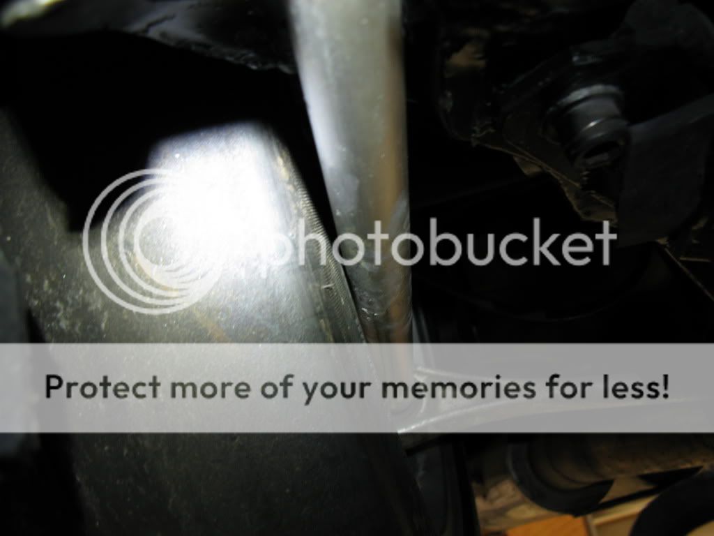
I install the trailing arms and during that I realized that my offset bushing made the links hit the subframe. A little bit of cutting, moving, and re-welding some metal and that issue was fixed. I had to cut, move and weld some parts where the trailing arm passes by.
And pics.
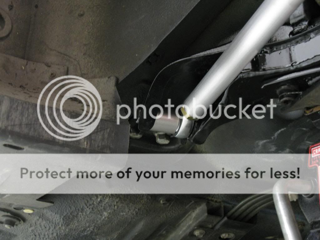

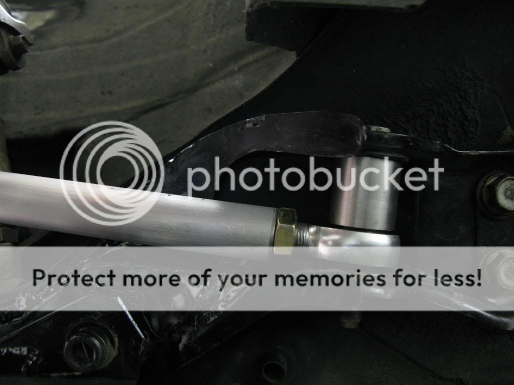
In that last pic you can see where the trailing arm passes by the subframe, and I had to move that out of the way to get clearance. Before I modified it, the trailing arm wasn't even able to be installed, much less clear it at full compression.
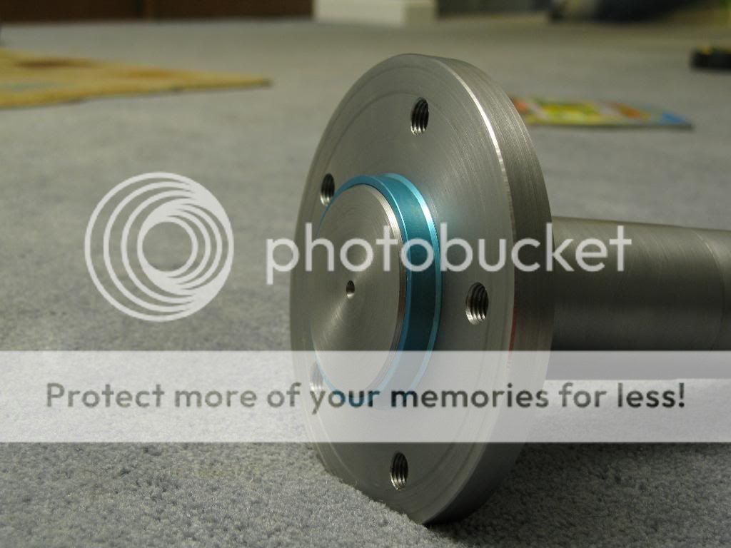
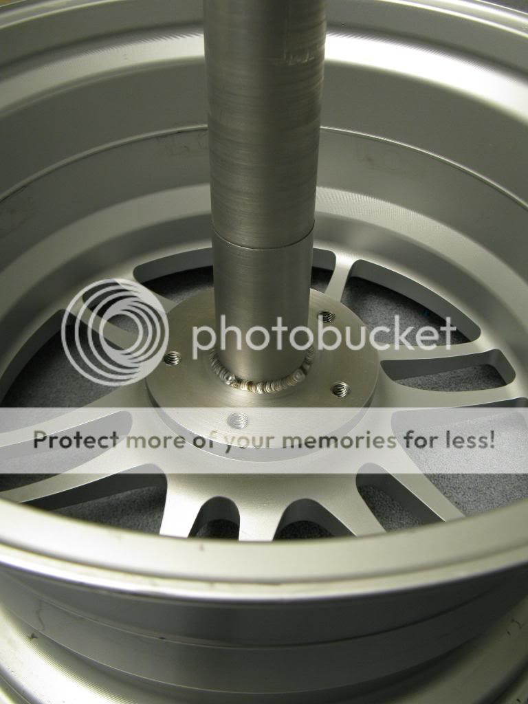
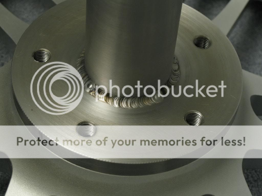
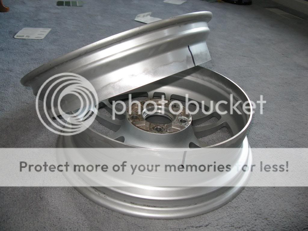
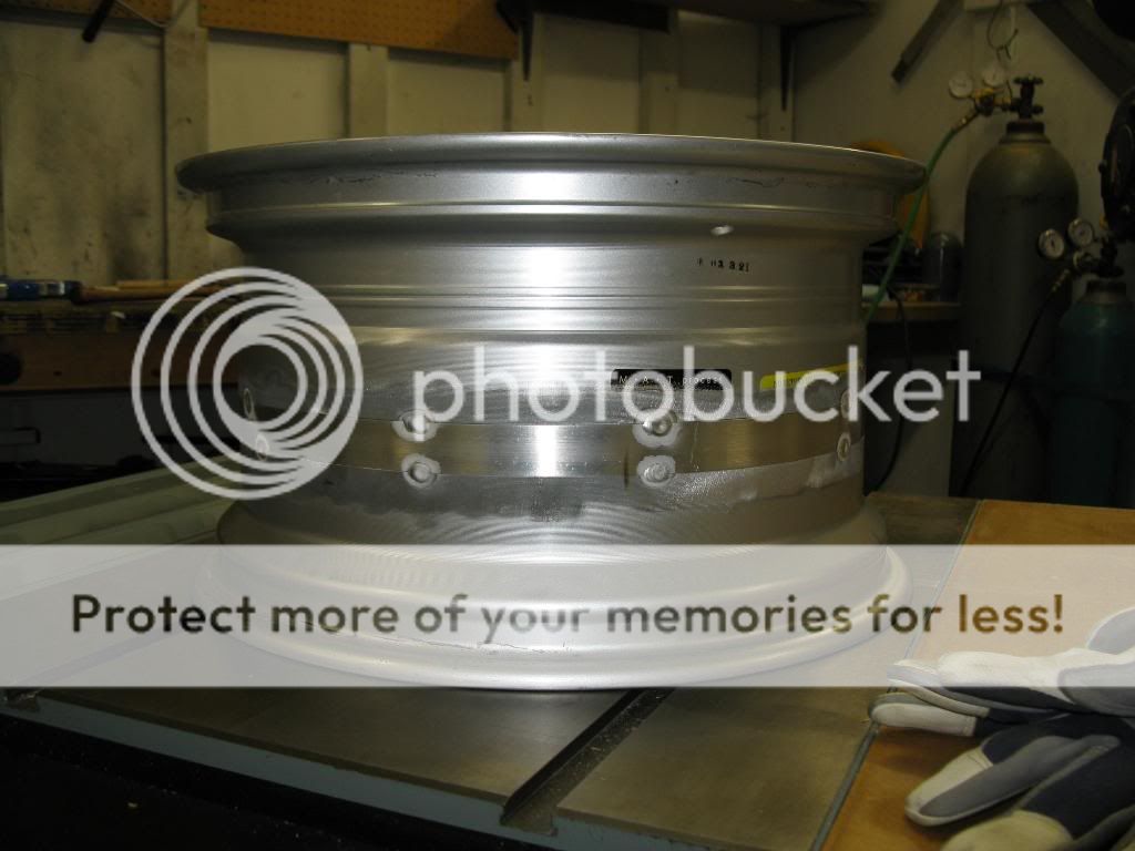
So next step was to widen my wheels. I needed to make a fixture to hold the wheel in the lathe while it was being cut. So I designed and built this little guy. Its two pieces, pressed together, then welded, then machined after welding to ensure concentricity even if it warped from the heat.
Finished up my fixture to mount a wheel on the lathe. Just need to get some quality bolts to thread through as wheel studs and it will be complete and ready for use.
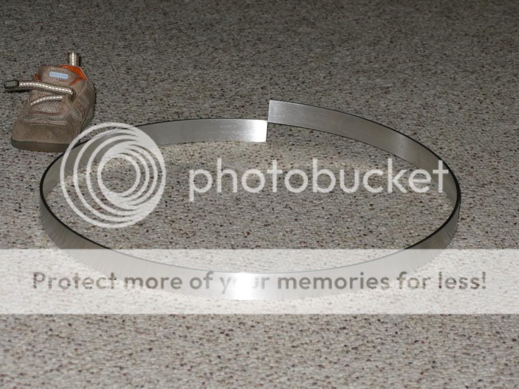
I talked to a materials engineer where I work, and a weld engineer as well about welding these wheels. I was able to determine the casting alloy and go the right filler rod, and right material for the add in strip. I ended up using a 6061T6 strip, adn 4043 filler. Pretty standard. I also purchased a junk Enkei wheel that was curbed for cheap to practice on.
I just cut my practice wheel. Went pretty well. Cut an overall of 1/4" of material away. I'm gonna add a 1" strip here soon, as soon as I get it rolled up. The thickness is 1/8".

Got the strip cut to length and rolled up.
Enough of that foolishness.....
I finished up my practice wheel today. Got the strip tacked on with a super high tech jig. Then put the other half on using a framing square on a flat cast iron surface and feeler gauges.
And the pics...
Method to hold the strip centered up on the wheel as I tack it into place.
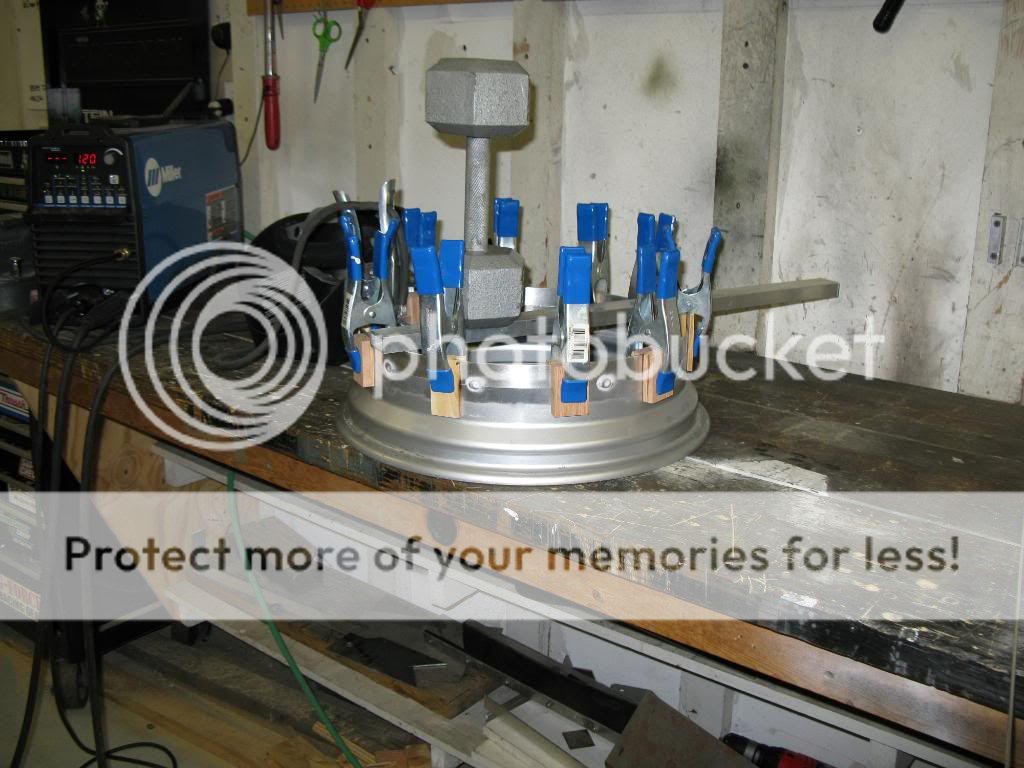
Both sides of strip tacked into place, ready to fully weld. (I double checked alignment again at this point).
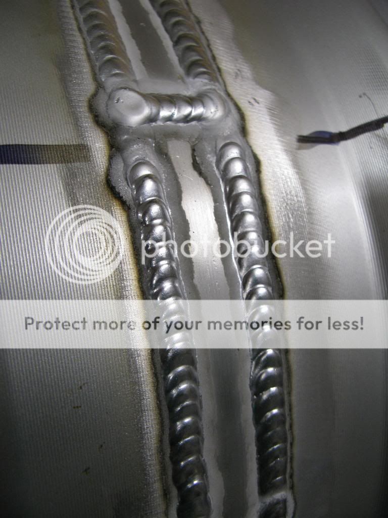
Fully welded on the inside and outside.
Weld consistency closeup.
Thanks guys!
I welded my good wheels. I measured runout before and after welding. I also mounted a race tire on one and balanced it out. It balanced out to 3 lbs of road force and 1/2 oz. Perfecto.
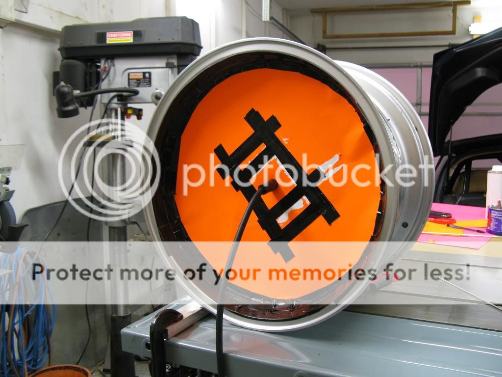
Here is my backpurge setup for welding the outside of the wheel.
Here is some welding videos I took with my camera. Those of you interested in the welder settings they were as follows: Dynasty 200DX. 3/32" ceriated tungsten. #12 cup, 125A, 80 balance, 150 Hz freq, 4043 filler, 1/8" diameter filler, A356 to 6061-T6 both 1/8" thick.
Welding Wheels.AVI
Welding wheels closeup.AVI
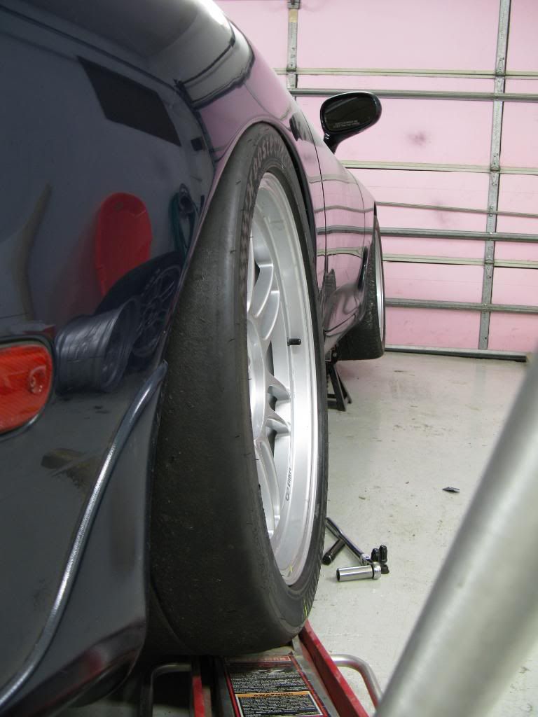
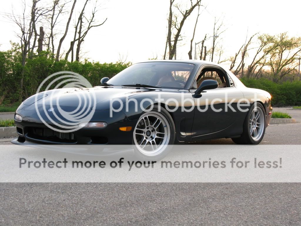
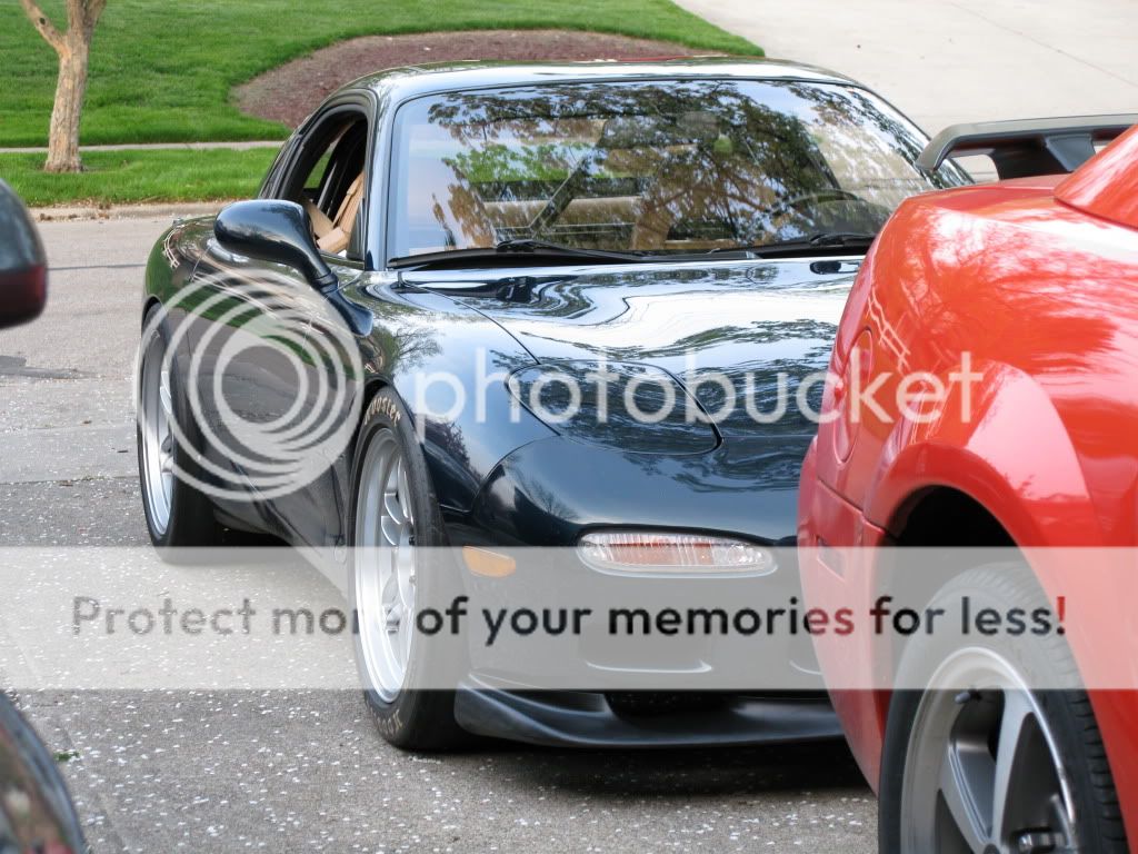
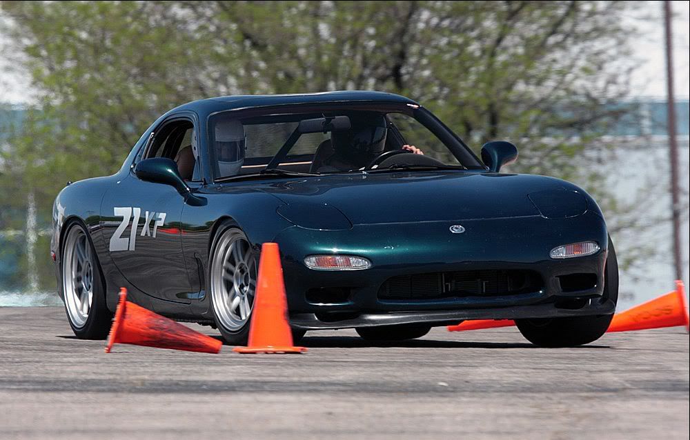
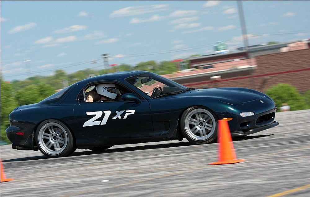
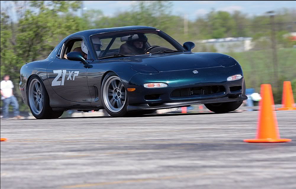
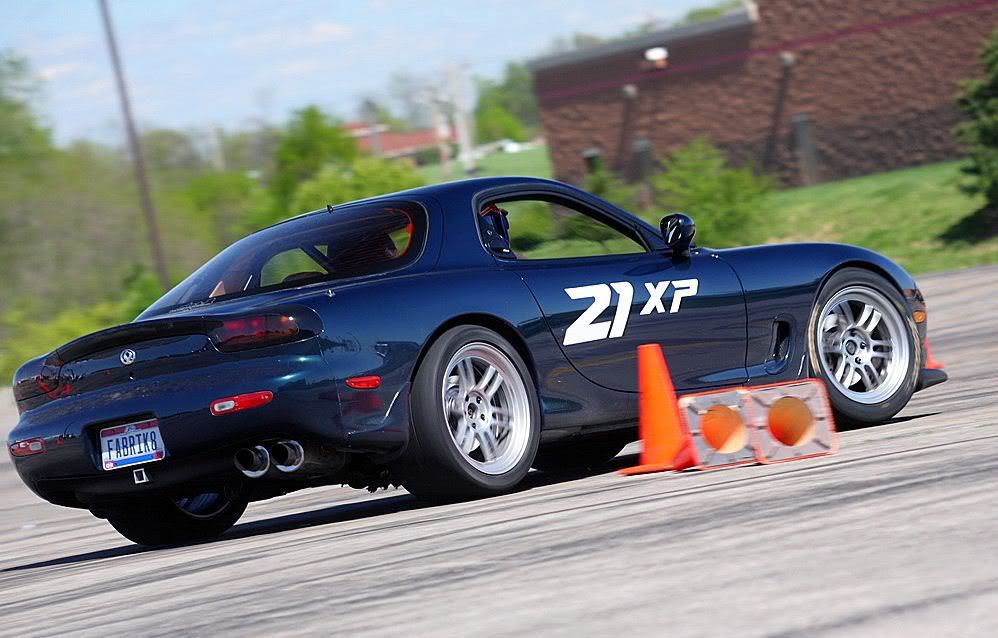
No real finished welded pictures yet. I forgot to take pics before i mounted the tire and put it on the car. Here are some pics on the car. It won't tuck the tires in the quarters, I need to do some more fender rolling. Its close so I don't think I'll have any issue making it work.
I'll call this "hellafunctional" just to spite all the hellaflush dweebs.

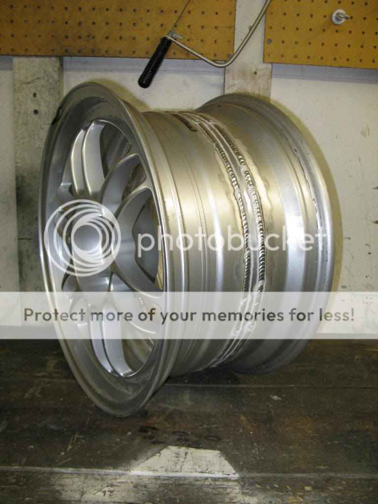
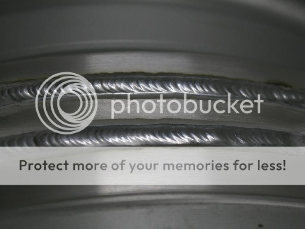
Here are some pics of the good wheel welded up, outside only for this one.
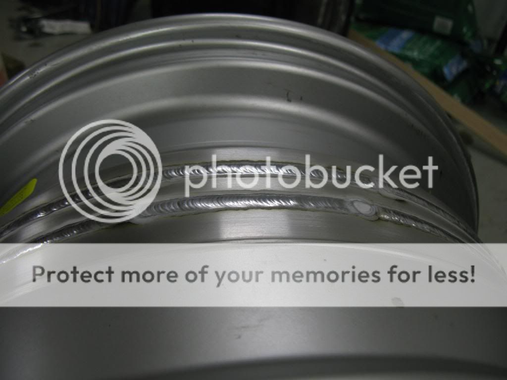
Closeup of the beads
Fully welded on the inside and outside.
Weld consistency closeup.
Thanks guys!
I welded my good wheels. I measured runout before and after welding. I also mounted a race tire on one and balanced it out. It balanced out to 3 lbs of road force and 1/2 oz. Perfecto.
Here is my backpurge setup for welding the outside of the wheel.
Here is some welding videos I took with my camera. Those of you interested in the welder settings they were as follows: Dynasty 200DX. 3/32" ceriated tungsten. #12 cup, 125A, 80 balance, 150 Hz freq, 4043 filler, 1/8" diameter filler, A356 to 6061-T6 both 1/8" thick.
Welding Wheels.AVI
Welding wheels closeup.AVI
No real finished welded pictures yet. I forgot to take pics before i mounted the tire and put it on the car. Here are some pics on the car. It won't tuck the tires in the quarters, I need to do some more fender rolling. Its close so I don't think I'll have any issue making it work.
I'll call this "hellafunctional" just to spite all the hellaflush dweebs.
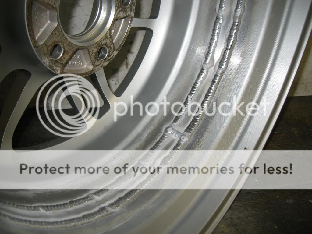
Here are some pics of the good wheel welded up, outside only for this one.
Closeup of the beads
And full penetrated, back purged inside. Probably a bit too much penetration, but it doesn't matter. I'm going to be running a bead on the inside as well.

Thanks!
Rolled my fenders, and now the wheels/tires fit. Its a very tight fit. The bead protector on the R6s is bigger than I thought it would be. I had to roll the fender lips pretty much flat.
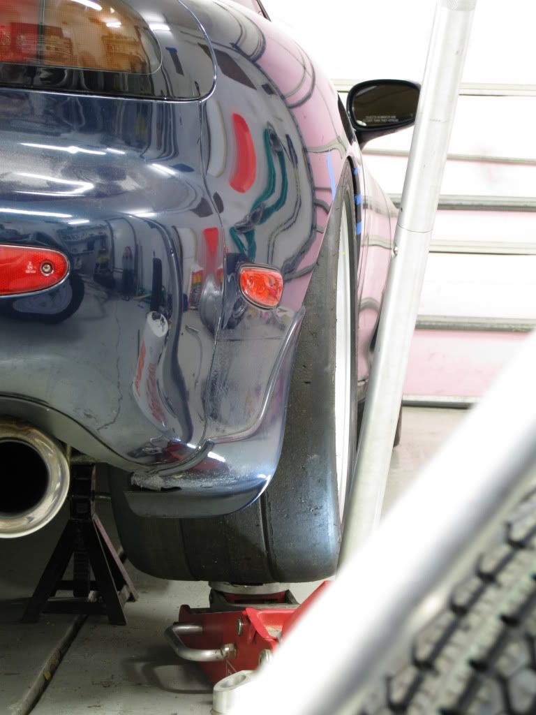
0.035" clearance to the bead protector. Thats with a ton of toe in, in the rear. With these stickier tires I'll probably run less toe in.
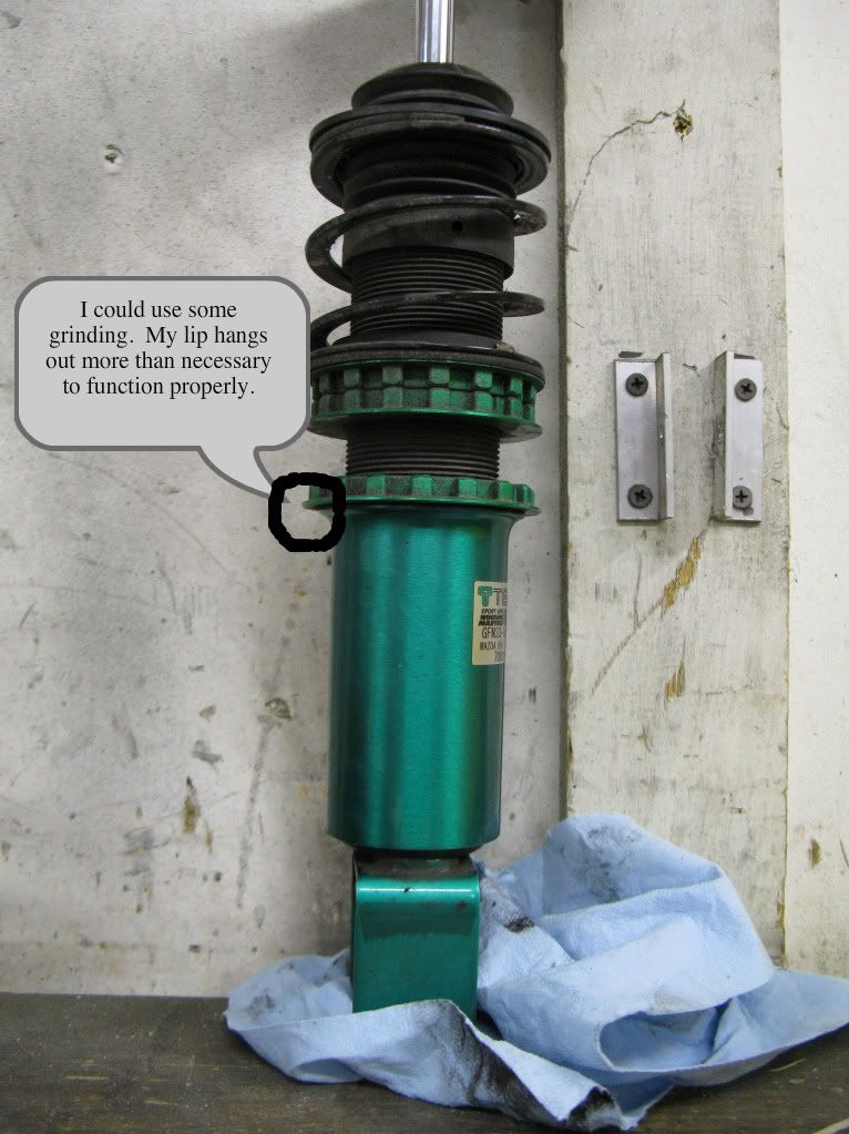
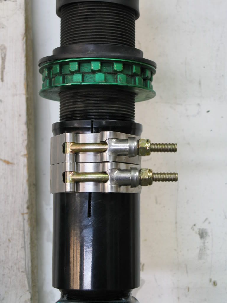
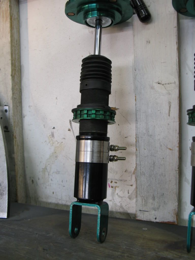
I just modified my rear lower shock mounts. I eliminated the locking ring and replaced it with a slit and two t-bolt clamps. I was able to gain 3/16" clearance by making this modification.
Original:
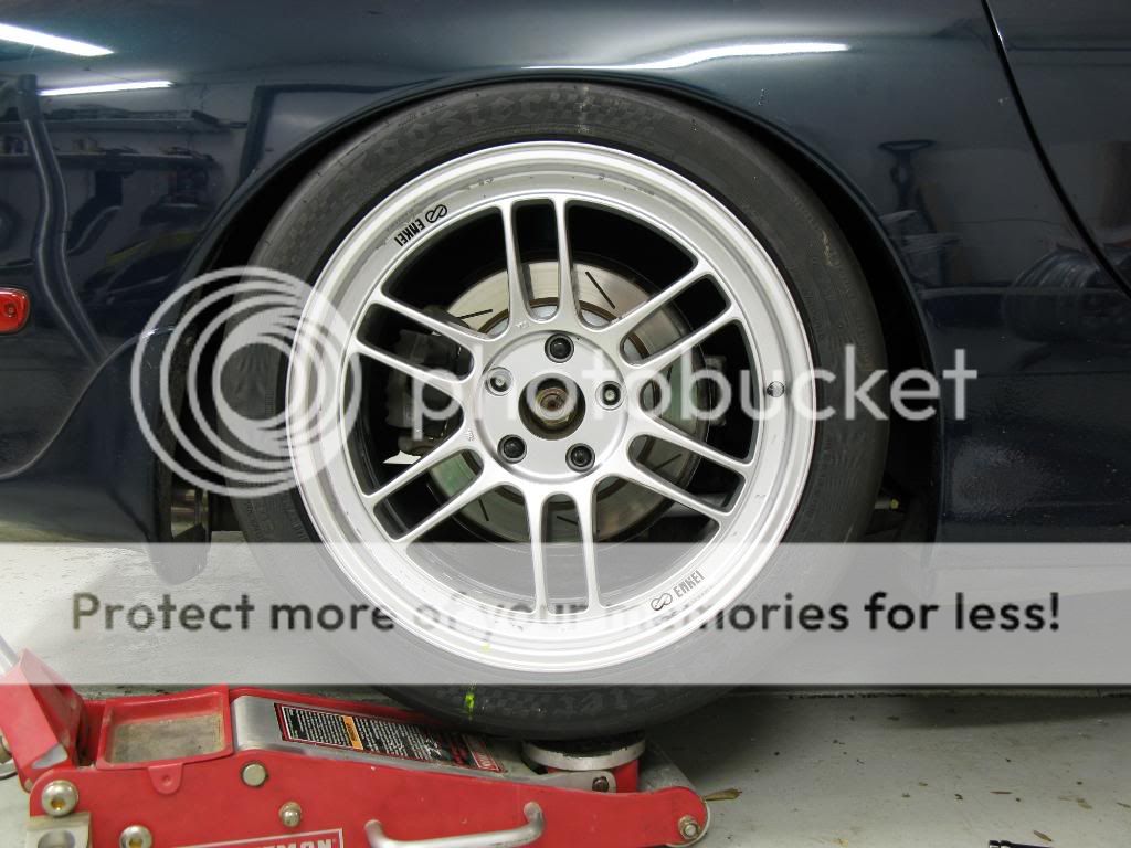
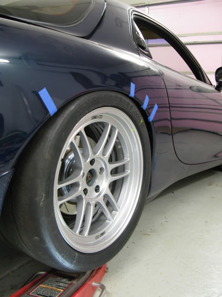
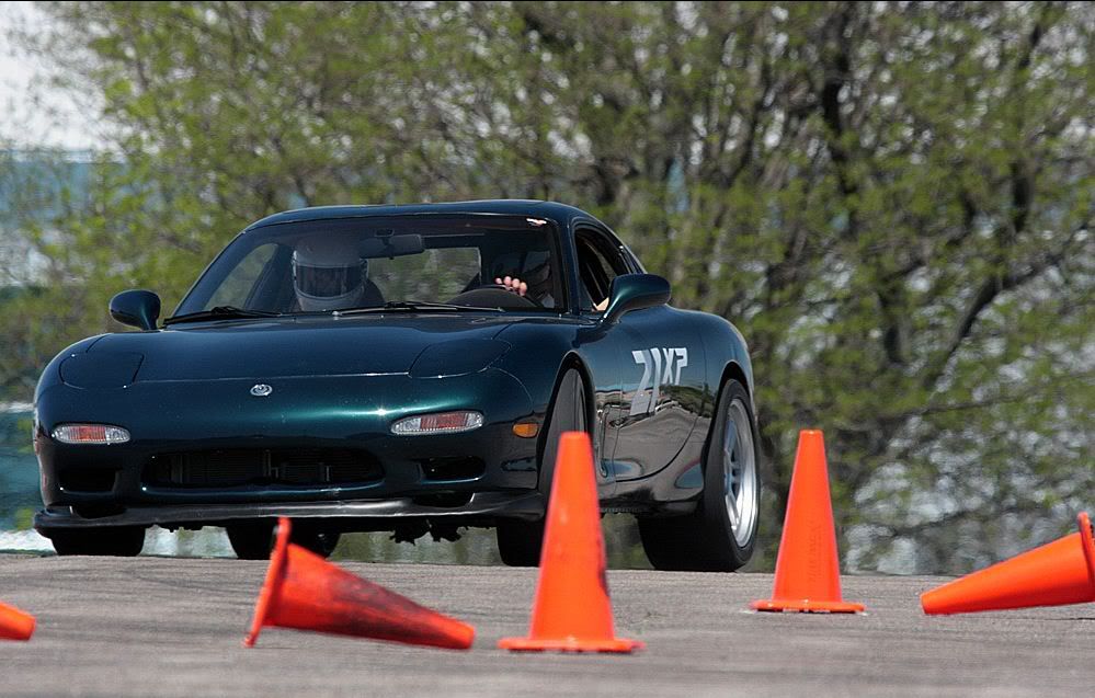
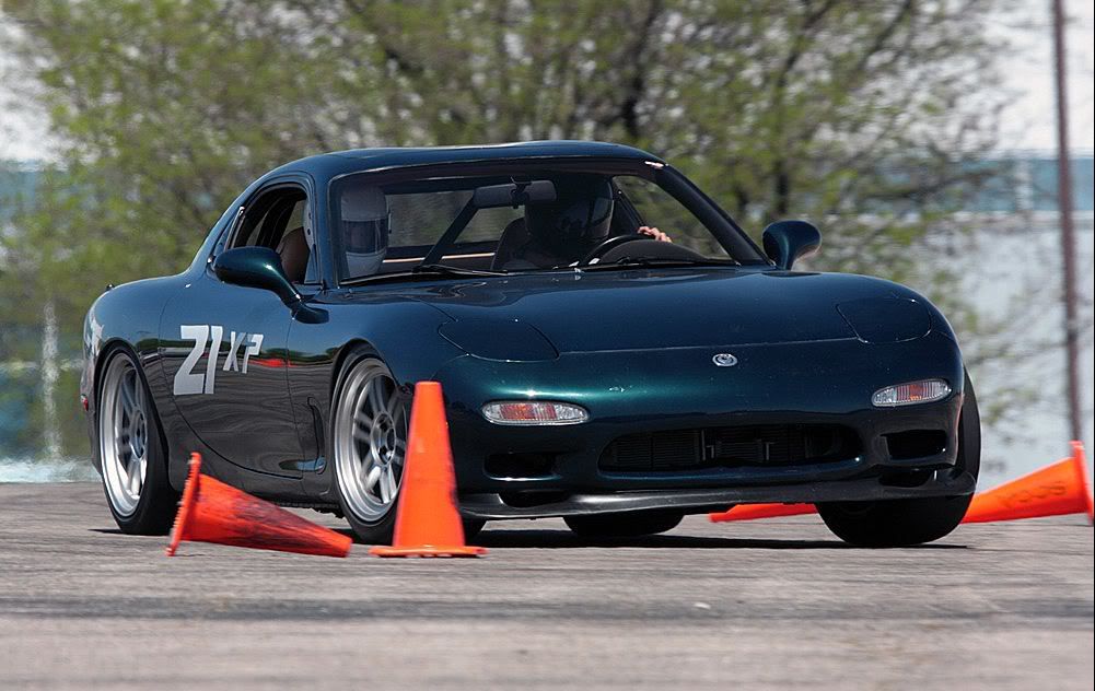
I didn't spend much time getting a good setting. I washed my car and wanted to get some pics of the new wheel/tire setup.
For right now I moved my old rears up front, and have the new 315s out back. So I have a 275/40/17 up front, and a 315/30/18 out back.


Thanks!
Rolled my fenders, and now the wheels/tires fit. Its a very tight fit. The bead protector on the R6s is bigger than I thought it would be. I had to roll the fender lips pretty much flat.
0.035" clearance to the bead protector. Thats with a ton of toe in, in the rear. With these stickier tires I'll probably run less toe in.

I just modified my rear lower shock mounts. I eliminated the locking ring and replaced it with a slit and two t-bolt clamps. I was able to gain 3/16" clearance by making this modification.
Original:
I didn't spend much time getting a good setting. I washed my car and wanted to get some pics of the new wheel/tire setup.
For right now I moved my old rears up front, and have the new 315s out back. So I have a 275/40/17 up front, and a 315/30/18 out back.


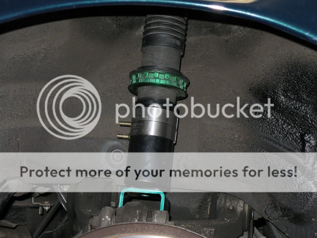
Since I've got my wider wheels done, and clearing most things it was time to set the alignment to something a bit more aggressive. Right now I'm sitting at 1 degree of negative camber, but I'd like to be at more like 2.5 degrees of negative camber. The clearance between the tire and the shock body was very close, and at full suspension compression the rubber slightly rubbed.
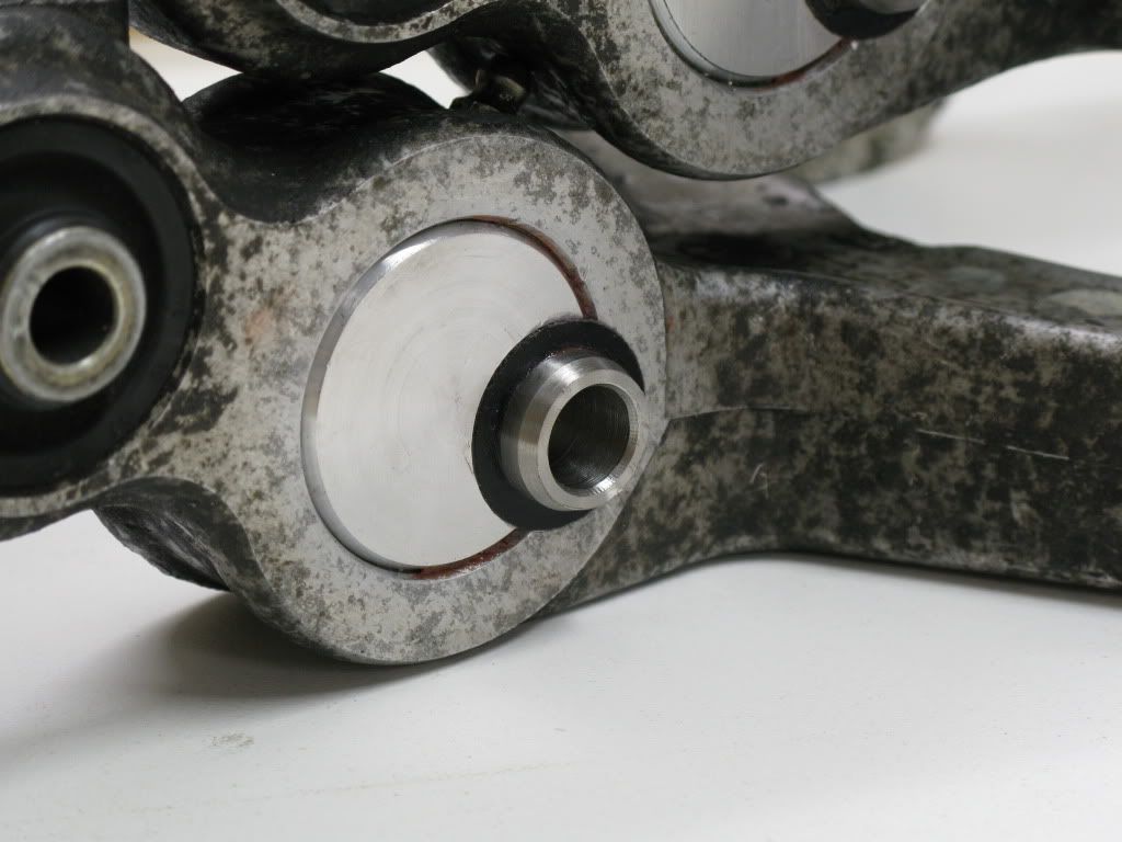
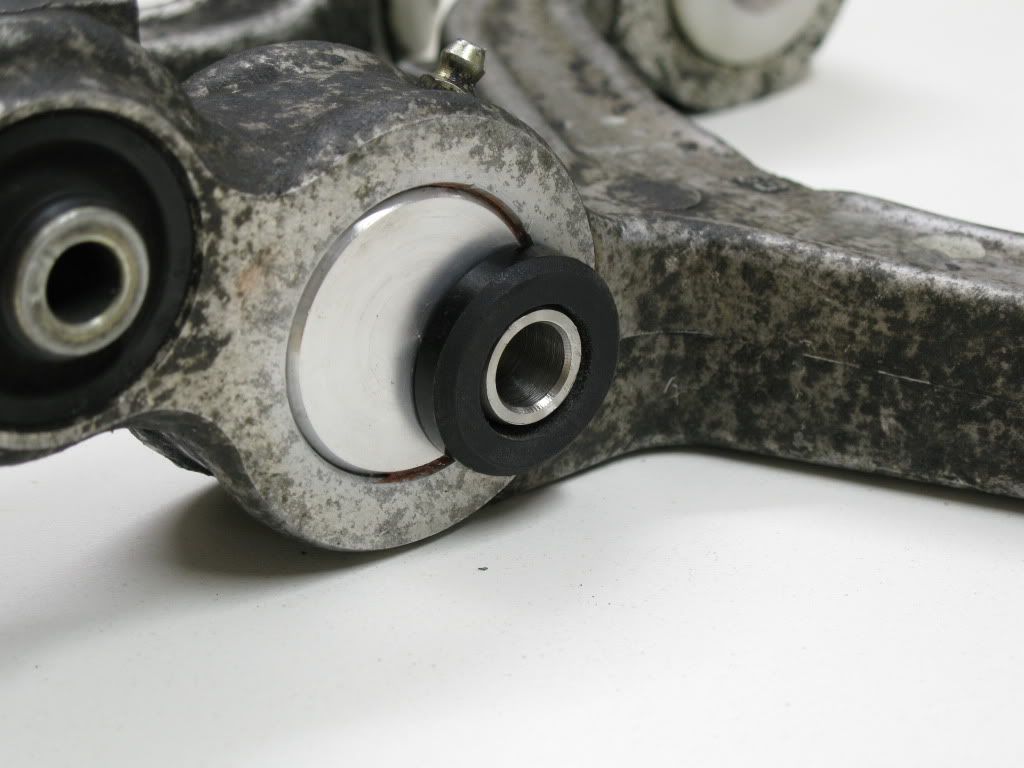
That needed to be fixed. So, to fix this the shock needed to be moved inboard a bit. With the geometry of where it rubbed (about halfway up the shock body), whatever amount I moved the mount, I'd gain about half that in clearance where it was touching. So, I came up with a plan, an eccentric bushing for the lower shock mount, on the upper control arm. Then I took that solution a bit further to get even more offset.
What I did was make my own bushing. I started with solid 7/8" stainless rod. I used this as the center pin of my bushing. I drilled it out to 12mm and turned the outside down to a 0.125" wall thickness. The pin is the length of the ID of the shock mount, minus some clearance to make sure it assembled well.
Then I needed a bushing. I bought some stiff polyurethane stock, and also some delrin. I was unsure that Id' be able to machine the poly in a lathe, so I bought the delrin as a backup. To get much offset I had to make the wall thickness of the bushing relatively thin. To keep a decent amount of compliance (to ensure the seals in the shocks last a long time) I preferred the poly over the delrin. After one attempt, I machined the poly bushings. I made them 1/8" wall thickness as well. They did not machine that well, so the finish was not that great. I should have researched cutting tool rake angles before I made them, oh well. They turned out decent enough. I made them the length of the width of the control arm (1.5"). I also made some biscuits to keep the bushing from moving side to side in the control arm, and to keep the shock centered.
Next I made two plugs and pressed them into the control arm. Once pressed into the control arm, I drilled the offset hole. I ended up offsetting them 5/8", which means I should gain approximately 5/16" clearance at the location of the rub. That should be enough to run more camber than I'd ever need to. I picked the area to bore by making sure the wall thickness around the hole was sufficient. I gave a little more on the bottom of the hole than the top, just because it would be the highest stress area based upon the loading of the piece.
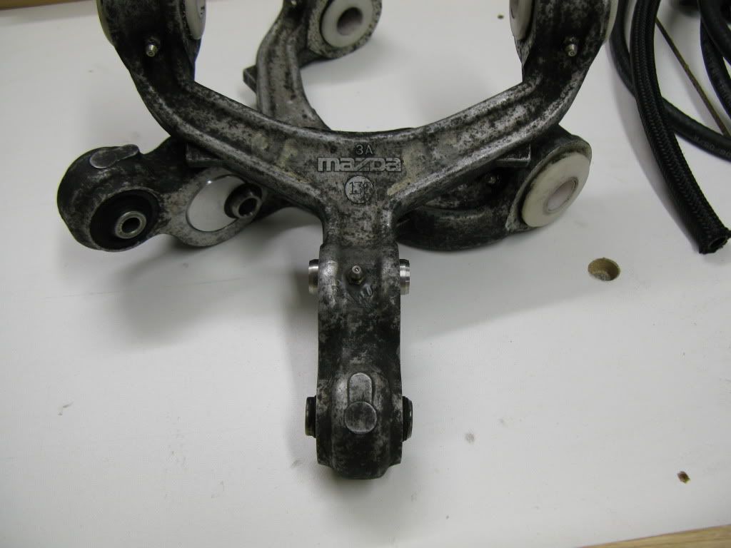
Bushing all installed and ready to put the control arm back in the car. Before i install I'll probably drill a small hole opposite of the bushing bore, between the plug I pressed in, and the original piece. I'll then tap the hole and install a set screw. That should keep the plug from wanting to rotate in the hole. Its pressed in with a 0.005" interference, and the pin is halfway between the two, but you can never be too careful.
Based upon my calculations, this effectively makes my springs less effective at the wheel, as well as the shock. To combat this I'll probalby need to turn up my damping adjustment to get the same wheel damping. And for spring rates at the wheel, it won't have a huge effect. It will be approximately 10% less effective. So it will make my 12k spring act more like a 10.8 kg/mm spring. We'll see if I need to change my springs, but I doubt it.


Trending Topics
First set of 18x11 RPF1 I ever heard about. Seriously Kevin I don't spend much time reading through everyone's DYI posts but this one seriously intrigued me and I gotta say you are a lucky man to have the time, material, and skills to do this. Welds are awesome.
I'm really impressed with the effort that you've put forth.
btw, I'll see your Dynasty and raise you an Aerowave (full feature) :-P
btw, I'll see your Dynasty and raise you an Aerowave (full feature) :-P
Last edited by hwnd; May 20, 2010 at 12:07 AM.
LOL, The Dynasty really is all I'll ever need I think, although the 300A model would be nice. 200A isn't really enough to do 1/4" aluminum plate unless you preheat, or have a relatively small part. Plus the torch gets really hot, so a water cooled setup would be nice.
Rishie, they're actually 18x10.75". Hahahahah. I added a 1" strip, but took 1/4" out when I sectioned them. You'll probably never see another set like them, unless Kukri can manage to convince me to make another set for him.
Thanks for the nice comments guys. I hope posting this kinda stuff gives other people some ideas for future fab projects.
Check out my car's build thread:
https://www.rx7club.com/v-8-powered-rx-7s-299/ls1-fd-build-thread-most-detailed-build-thread-earth-904544/
https://www.rx7club.com/v-8-powered-rx-7s-299/ls1-fd-build-thread-most-detailed-build-thread-earth-904544/


Oh ya I forgot to mention that I'm estimating this fitment as a
18x10.75 +57 offset
315/30/18
Based on 4" Front Spacing and 7.75" Back Spacing. Total "outer" spacing of 11.75" for your 10.75" wide wheel.
DOE-p fitment.
I believe the custom bushing you made correlates to the SuperPro SPF2680K.
Trying to cross reference it with this diagram.
https://www.rx7club.com/attachment.p...5&d=1248621385
How are you calculating this fitment to be 10.75 +57? I am doing something wrong in my calculation...
I am calculate this fitment as 10.75 +48...
I will assume that the outer portion of the widened wheel in relation to the fender is the same as the stock wheel because you widened the wheel not at the outer lip but in the center of the wheel.
According to the 1010 wheel calculator a 10 +38 wheel has the same relation to the fender as a 10.75 +48 wheel.
What am I doing wrong?
I have been considering widening my 10 +45 wheel to 10.5 in an attempt to fit a 315/35 17. What would the final offset be? What other modifications would you anticipate with such a wheel/tire package?
Thanks and great work!
-Andrew
well if you widen a rim by 1" ..then simply add 25.4mm to the offset; make sense?
...there is something else i've kept in mind while widening my wheels.. they had an original offset of +19mm but because of the extra width, they now have a +50mm offset (stock) so my scrub radii is still bang on.
...there is something else i've kept in mind while widening my wheels.. they had an original offset of +19mm but because of the extra width, they now have a +50mm offset (stock) so my scrub radii is still bang on.
Last edited by hwnd; May 30, 2010 at 09:17 PM.