
What affects turbo spool time other than the turbo itself?


What affects turbo spool time other than the turbo itself?
So as the title says I�m curious to find out what (and how) exactly influences turbo spool time other than the turbo itself (on a single turbo 13b).
For example:
- How does the design of the exhaust manifold affect turbo spool?
- What about stock intake ports vs. street port vs. bridge port etc affect spool? What about exhaust ports?
- How would an Xcessive LIM, ported UIM and modified big TB compare to a stock LIM, UIM and TB (all other things held constant) in regards to spool?
- Using a FMIC compared to a V-mount with minimum IC pipe length?
- How does the exhaust system affect spool (DP diameter, etc�)
What else (other than the turbo) would have an effect on the spool time on a 13b single turbo engine?
If any of these things do influence spool time would the average person be able to notice the difference? Or would the change in spool time be insignificant and unnoticeable to your average driver?
I always wonder about stuff like this�
(I figured the single turbo sub-forum would be a good place to ask...)

I'll give it a shot.
first definition.
"spool time". This is the time between the demand for an increase in power (the throttle being opened), and the turbocharger(s) providing increased intake pressure, and hence increased horsepower.
everything in the system effects spool time. everything.
It's the ability to expell exhaust gases in the most efficient manner down the exhaust manifold and spin your turbo. Now runner length, diameter, intake temps, compression of the motor, AFR ratio, the volume of the intercooler and intake tract, if any leaks in the system, air filter size, exhaust backpressure, moment of inertia of the intake and exhaust wheels themselves, the bearing type of the turbo, and when in gear, even the size of your wheels and tires and flywheel moment of inertia matter when spooling a turbo.
Ranking them in terms of what has the largest effect on spool times I am unsure of the most to least effect. I could take a guess.
I know tuning AFR wise and timing have a LARGE effect. compression of motor does, turbo size (turbine wheels and compressor wheel), size of turbine A/R, volume of the intercooler, and exhaust backpressure are probably big factors. The smaller factors might be a really small boost leak somewhere.
It's difficult to get exact figures on items because most people's systems are different and no control standard exists for comparing system to system. But in general, the size of the turbo and A/R (and flange size) of turbine are HUGE factors. I would also say compression of motor and tune. Those are the top three.
the smaller factors are exhaust manifold, intercooler piping, boost leaks, and diameter of exhaust piping (given it has no cat's).

Joined: Mar 2001
Posts: 31,857
Likes: 3,243
From: https://www2.mazda.com/en/100th/
if you use the same intercooler core for each setup, then the only difference in spool will be from any difference in the piping.
the front mount, typically will have longer pipes, and thus more volume for the turbo to fill. in practice you have to have either really big pipes or a too small turbo to notice this.
the other variable are the bends, straighter is better for flow, so a V mount should do better here as well, although if the FMIC has the right diameter of pipe so the bend isn't restrictive, it'll perform the same.
so in the real world a well constructed FMIC won't have any measurable lag vs a well done V mount, given that the core is the same between the two.
this is very simple, part of why (and how well) a turbo works depends on the pressure difference between the inlet and exit of the turbo. ideally you would like a big difference. so the less restriction you have in the exhaust the better the turbo works.
this is very noticeable when you go from say a stock exhaust, with a catalytic converter, to a 3" straight through system. putting a pressure gauge after the turbo is a very easy way to test this.
the front mount, typically will have longer pipes, and thus more volume for the turbo to fill. in practice you have to have either really big pipes or a too small turbo to notice this.
the other variable are the bends, straighter is better for flow, so a V mount should do better here as well, although if the FMIC has the right diameter of pipe so the bend isn't restrictive, it'll perform the same.
so in the real world a well constructed FMIC won't have any measurable lag vs a well done V mount, given that the core is the same between the two.
- How does the exhaust system affect spool (DP diameter, etc�)
this is very noticeable when you go from say a stock exhaust, with a catalytic converter, to a 3" straight through system. putting a pressure gauge after the turbo is a very easy way to test this.
Thanks for the feedback. Regarding the IC volume, if I wanted to aim for a faster spool I guess I wouldn't want to go overboard on IC volume, right?
You know those forced induction setups without an IC, where the turbo directly feeds the intake...what would be the main purpose of this? What exactly do you gain by not using an IC, and is it worth it considering the power loss from not using an IC? Whats up with some drag cars that use big turbos straight to the intake without an IC?
You know those forced induction setups without an IC, where the turbo directly feeds the intake...what would be the main purpose of this? What exactly do you gain by not using an IC, and is it worth it considering the power loss from not using an IC? Whats up with some drag cars that use big turbos straight to the intake without an IC?
Joined: Oct 2001
Posts: 6,279
Likes: 728
From: Florence, Alabama
that is a GREAT question.
if you download the WinPEP 7 software and then get the FILE from your Dynojet tuner rather than a dyno sheet and look at the boost data V power you will quickly see that boost and power correlate directly. perhaps more directly than you might have expected.
airflow drives power so the question re spool is central. many of us just look at the turbo which is of course a central factor but there are many many other components that greatly effect airflow that are often not given their due.
having a NA background adds a helpful perspective.
airflow is everything in both the turbo and NA world and NA does not have the benefits of a pile driving compressor. NA has to depend on 14.7 psi to get it done.
the turbo covers for many engineering sins.
turbos are magic as to being power adders so we can be sloppy and make big power.
you can't be sloppy w NA. if a Pro Stock engineer looked at the typical FD engine bay he would not be impressed. (nice way of saying it)
my background is NA. i am of course not in the Pro Stock category engineering-wise but i built and raced 10,000 rpm overhead cam motors for approx 15 seasons. i worked w a Flow Bench and engine dyno and we were looking for (literally) every CFM we could get. i worked w Competition Cams designing camshafts for my motors so i am quite familiar w valve timing, duration, overlap etc.
and all of this directly relates to the turbo'd rotary.
by applying the much more aggressive NA flow mindset to the turbo setup it is possible to gain advantages at the margin.
i have owned my FD since 1999 and have finally gotten it to near what i want. i have had a lot of fun with it during the process. for four years i ran a twin TO4 turbo setup w two three inch downpipes etc etc.
it is pretty close to what i want currently.
most of the setup is applied NA tech.
here's a pic taken in November. let's go thru a few things which directly relate to spool/airflow.
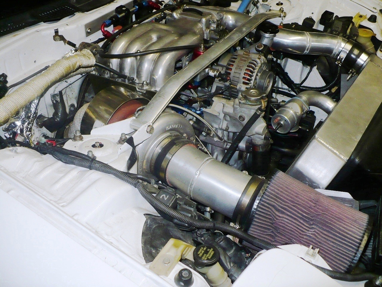
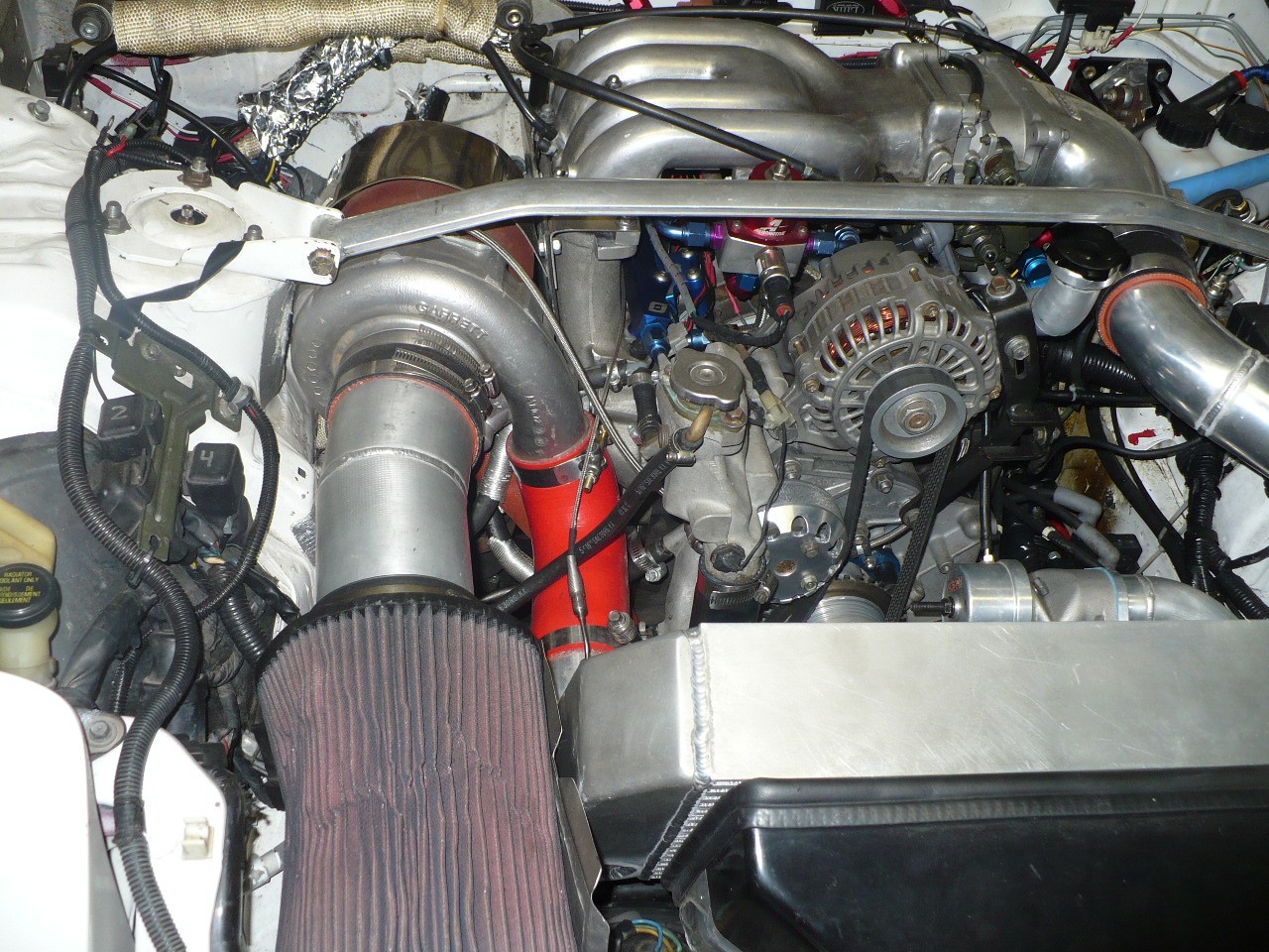
turbo manifold engineering is central to airflow as there are so many aspects that are affected.
lets start w where the air enters the picture.... the filter. filters add restriction. the larger they are the less restriction. my manifold/system/intercooler is designed to allow a large filter. it is 7 inches in diameter by 9 inches in length. a 500 hp rotary requires 960 CFM whereas a piston engine needs 750. what's the restriction of your filter at 1000 CFM?
this is one of my unfinished areas. the air inside the engine compartment is often 165 degrees. sucking engine compartment air into the engine is, uh, less than optimum. i will find a proper way to get 100% outside air before the snow melts. what makes power is oxygen molecules. hot air has less oxygen per volume.
at 20 psi boost or more the turbo is producing 300 degree charge air. take 70 degrees out of the incoming air and good things happen in both the spool, power and reliability areas. outside air is the key.
item two is intercooler tubing volume... less is more. more of the good things. notice the short straight run to the intercooler. (picture two)
the Pettit Cool Charge intercooler was modded by old racing buddy Cam Worth so the inlet lines up perfectly w my GT4094r turbo. NA tech at work.
moving further downstream note the BOV location. many BOVs are located in the tube between the IC and the elbow. this is an important tube flow-wise and the idea of butchering it w a hole almost the same diameter as the tube is crazy. take a good look inside this tube at the BOV hole and imagine what it does to the flow. the BOV simply relieves pressure created when the throttle plates close and can be anywhere in the system. i located the hole/impediment where it would do the least damage which is on the flat surface of the end tank.
creating a smooth uninterrupted flow thru the IC/elbow tube.
ports are the elephant in the spool room. the exhaust port configuration is a major factor in the spooltrain.
the exhaust ports on the 13BREW are huge.
the exhaust ports on the 13BREW are peripheral
the exhaust ports on the 13BREW are open a long time
the exhaust ports on the 13BREW close late in relation to the intake open
the exhaust ports on the 13BREW are just on the edge of being too wide to help the apex seal
the exhaust ports when properly modded can help spool.
since most of the power from the combustion process is gone because of the port efficiency the exhaust port can be opened a tad earlier redirecting a small amount of power from the rear wheels to a more important wheel.... the turbo Turbine Wheel. this hits the turbo harder and makes more spool/power which drives the rear wheels harder net.
here's a pic of the redirected power applied concept:
manifold design is central to spool.
certain parts of my manifold thinking is not "settled science." in other words others may have different ideas and they could be right. we could debate short tube long tube and tube diameters forever. which is fine w me. i have my ideas and you are welcome to have yours.
i like short straight large runners for the rotary. the rotary has to flow approx 30% more air than the piston engine to make the same power. that also means that it flows a lot more exhaust. the rotary produces about 300 F higher EGTs than a piston engine. it is an especially good thing to get the heat out of the motor and drive the turbine.
most manifolds place the turbo further forward than my design. further forward involves placing the turbine further from the explosion, creates more flow drag from the longer runner, transfers less heat to the turbine as well adding additional bends.
there is room in the engine bay to place the T3- T4 turbine housing very close to equidistant between the two exhaust ports with only one bend. this places the turbine assembly, which gets cherry red at high boost, within 1/2 inch of the lower intake manifold... the aluminum manifold. aluminum is one of the most heat conducting materials on the planet.
not good for consistent AFRs front to rear when the front runner is much much hotter than the rear.
enter the solution:
MICA
my manifold design would not work without a simple 1/4 inch thick Mica heat barrier.
McMaster-Carr #85165K82 10 X 12 X .25
do not confuse this w something like stainless steel.
i hit one side of a Mica sheet w a propane torch (1300 F) for two minutes and could touch the other side w my finger. (don't do that w SS)
you can see the Mica in the top two pics.
the Mica allows for placement of the turbo very close to the engine and reduces runner bends.
wastegate placement is another important flow factor. here again my NA experience leads me to place the flow-disruptive WG holes in the least disruptive position.... in a runner area that is straight. the worst possible position would be on the outside of a bend. the most important flow area of the manifold is the initial turn at the flange. it needs to be big and smooth w no interruptions.
i use one Tial 60 mm wastegate. simple w only two V bands, one tube to re-join the DP and 4.38 sq inches of area. plenty of WG piston to control boost. i do use a dividing panel to retain most of the individual pulsing. in this area twin WGs may have an advantage but i like the simplicity of the large single WG. twin 44s have 4.71 sq inches of area or 7% more than my 60.
the area of the exhaust port (50 mm dia) is larger than the area of the T4 rectangle at the turbo flange. keep the manifold large at the motor especially as it has to make a turn and then neck it down to T4 area linearly where it is straight.
WG size and placement is a balancing act. from a flow standpoint you want no WG. it is a disruptive hole. of course a WG is needed to control boost. i want as little disruption as i can get away with and have designed my WG system with that in mind.
once designed i have spent time w the WinPEP 7 boost data file measuring Standard Deviation and am very satisfied w the real world WG performance. other items that are worthy of consideration is the heat sensitive end of the WG that contains the silicone diaphragm. it needs to be away from the heat. my WG end is positioned in the open area of the subframe and is washed w ambient air.
finally, the outlet of the WG should enter the DP at a non disruptive angle.
in addition to hardware spool is greatly affected by software... tuning.
when talk of EGTs surfaces it is generally about peak EGTs. when we talk spool EGTs should enter the picture.
what are your EGTS from zero boost to one bar? do you look at them? do you tune them? you want to see 1400 in this area. more heat, more drive to your turbo.
spool and flow efficiency as you can see involve a whole lot more than the turbo.
howard
if you download the WinPEP 7 software and then get the FILE from your Dynojet tuner rather than a dyno sheet and look at the boost data V power you will quickly see that boost and power correlate directly. perhaps more directly than you might have expected.
airflow drives power so the question re spool is central. many of us just look at the turbo which is of course a central factor but there are many many other components that greatly effect airflow that are often not given their due.
having a NA background adds a helpful perspective.
airflow is everything in both the turbo and NA world and NA does not have the benefits of a pile driving compressor. NA has to depend on 14.7 psi to get it done.
the turbo covers for many engineering sins.
turbos are magic as to being power adders so we can be sloppy and make big power.
you can't be sloppy w NA. if a Pro Stock engineer looked at the typical FD engine bay he would not be impressed. (nice way of saying it)
my background is NA. i am of course not in the Pro Stock category engineering-wise but i built and raced 10,000 rpm overhead cam motors for approx 15 seasons. i worked w a Flow Bench and engine dyno and we were looking for (literally) every CFM we could get. i worked w Competition Cams designing camshafts for my motors so i am quite familiar w valve timing, duration, overlap etc.
and all of this directly relates to the turbo'd rotary.
by applying the much more aggressive NA flow mindset to the turbo setup it is possible to gain advantages at the margin.
i have owned my FD since 1999 and have finally gotten it to near what i want. i have had a lot of fun with it during the process. for four years i ran a twin TO4 turbo setup w two three inch downpipes etc etc.
it is pretty close to what i want currently.
most of the setup is applied NA tech.
here's a pic taken in November. let's go thru a few things which directly relate to spool/airflow.
turbo manifold engineering is central to airflow as there are so many aspects that are affected.
lets start w where the air enters the picture.... the filter. filters add restriction. the larger they are the less restriction. my manifold/system/intercooler is designed to allow a large filter. it is 7 inches in diameter by 9 inches in length. a 500 hp rotary requires 960 CFM whereas a piston engine needs 750. what's the restriction of your filter at 1000 CFM?
this is one of my unfinished areas. the air inside the engine compartment is often 165 degrees. sucking engine compartment air into the engine is, uh, less than optimum. i will find a proper way to get 100% outside air before the snow melts. what makes power is oxygen molecules. hot air has less oxygen per volume.
at 20 psi boost or more the turbo is producing 300 degree charge air. take 70 degrees out of the incoming air and good things happen in both the spool, power and reliability areas. outside air is the key.
item two is intercooler tubing volume... less is more. more of the good things. notice the short straight run to the intercooler. (picture two)
the Pettit Cool Charge intercooler was modded by old racing buddy Cam Worth so the inlet lines up perfectly w my GT4094r turbo. NA tech at work.
moving further downstream note the BOV location. many BOVs are located in the tube between the IC and the elbow. this is an important tube flow-wise and the idea of butchering it w a hole almost the same diameter as the tube is crazy. take a good look inside this tube at the BOV hole and imagine what it does to the flow. the BOV simply relieves pressure created when the throttle plates close and can be anywhere in the system. i located the hole/impediment where it would do the least damage which is on the flat surface of the end tank.
creating a smooth uninterrupted flow thru the IC/elbow tube.
ports are the elephant in the spool room. the exhaust port configuration is a major factor in the spooltrain.
the exhaust ports on the 13BREW are huge.
the exhaust ports on the 13BREW are peripheral
the exhaust ports on the 13BREW are open a long time
the exhaust ports on the 13BREW close late in relation to the intake open
the exhaust ports on the 13BREW are just on the edge of being too wide to help the apex seal
the exhaust ports when properly modded can help spool.
since most of the power from the combustion process is gone because of the port efficiency the exhaust port can be opened a tad earlier redirecting a small amount of power from the rear wheels to a more important wheel.... the turbo Turbine Wheel. this hits the turbo harder and makes more spool/power which drives the rear wheels harder net.
here's a pic of the redirected power applied concept:
manifold design is central to spool.
certain parts of my manifold thinking is not "settled science." in other words others may have different ideas and they could be right. we could debate short tube long tube and tube diameters forever. which is fine w me. i have my ideas and you are welcome to have yours.
i like short straight large runners for the rotary. the rotary has to flow approx 30% more air than the piston engine to make the same power. that also means that it flows a lot more exhaust. the rotary produces about 300 F higher EGTs than a piston engine. it is an especially good thing to get the heat out of the motor and drive the turbine.
most manifolds place the turbo further forward than my design. further forward involves placing the turbine further from the explosion, creates more flow drag from the longer runner, transfers less heat to the turbine as well adding additional bends.
there is room in the engine bay to place the T3- T4 turbine housing very close to equidistant between the two exhaust ports with only one bend. this places the turbine assembly, which gets cherry red at high boost, within 1/2 inch of the lower intake manifold... the aluminum manifold. aluminum is one of the most heat conducting materials on the planet.
not good for consistent AFRs front to rear when the front runner is much much hotter than the rear.
enter the solution:
MICA
my manifold design would not work without a simple 1/4 inch thick Mica heat barrier.
McMaster-Carr #85165K82 10 X 12 X .25
do not confuse this w something like stainless steel.
i hit one side of a Mica sheet w a propane torch (1300 F) for two minutes and could touch the other side w my finger. (don't do that w SS)
you can see the Mica in the top two pics.
the Mica allows for placement of the turbo very close to the engine and reduces runner bends.
wastegate placement is another important flow factor. here again my NA experience leads me to place the flow-disruptive WG holes in the least disruptive position.... in a runner area that is straight. the worst possible position would be on the outside of a bend. the most important flow area of the manifold is the initial turn at the flange. it needs to be big and smooth w no interruptions.
i use one Tial 60 mm wastegate. simple w only two V bands, one tube to re-join the DP and 4.38 sq inches of area. plenty of WG piston to control boost. i do use a dividing panel to retain most of the individual pulsing. in this area twin WGs may have an advantage but i like the simplicity of the large single WG. twin 44s have 4.71 sq inches of area or 7% more than my 60.
the area of the exhaust port (50 mm dia) is larger than the area of the T4 rectangle at the turbo flange. keep the manifold large at the motor especially as it has to make a turn and then neck it down to T4 area linearly where it is straight.
WG size and placement is a balancing act. from a flow standpoint you want no WG. it is a disruptive hole. of course a WG is needed to control boost. i want as little disruption as i can get away with and have designed my WG system with that in mind.
once designed i have spent time w the WinPEP 7 boost data file measuring Standard Deviation and am very satisfied w the real world WG performance. other items that are worthy of consideration is the heat sensitive end of the WG that contains the silicone diaphragm. it needs to be away from the heat. my WG end is positioned in the open area of the subframe and is washed w ambient air.
finally, the outlet of the WG should enter the DP at a non disruptive angle.
in addition to hardware spool is greatly affected by software... tuning.
when talk of EGTs surfaces it is generally about peak EGTs. when we talk spool EGTs should enter the picture.
what are your EGTS from zero boost to one bar? do you look at them? do you tune them? you want to see 1400 in this area. more heat, more drive to your turbo.
spool and flow efficiency as you can see involve a whole lot more than the turbo.
howard
Last edited by Howard Coleman; Dec 14, 2013 at 01:44 PM.
talking head
Joined: Apr 2008
Posts: 2,775
Likes: 15
From: Perth, WA, OZ
in a situation where most of these variables are compromised due to packaging constraints for dimensions and competition for available airflow
then the two most significant factors that would make a difference between two externally similar setups
would be timing and fueling,, both of which would take an OPPOSITE train of thought to that in an NA application
in the NA application , maximum TQ at near wide open throttle and at or just under atmospheric pressure is what you are tuning for
in the NA, in the low vacuum zones ...the timing and AFR are adjusted for maximum TQ at the wheels
in the turbo application , you can take this path,, and whilst it makes the engine more efficient whilst "off turbo" it will spool slower than a similar setup where maximum exhaust energy was a priority over the wheel TQ
ie.. one setup is deliberately setup timed late,, and slightly rich,, to enable less of its energy to be transferred to the crank in this low vacuum load zone ( less wheel TQ ) but at the boon of allowing it to "afterburn" pre turbo and thus the energy at the exhaust wheel is significantly higher
in effect,, antilag whilst in gear with foot buried ,, makes a much more bell shaped ( nothing, then everything ) power delivery,, but the turbo can be make to work harder at significantly lower rpms
OEM street cars tend not to follow this formula because it is not at all fuel efficient, emissions friendly,, or easy to drive sedately
drag engines,, and rally ones,, often take the other route,, and indeed use similar principles for antilag off the line
When I was tuning my car, I was playing around with just the AFR. the difference between 13.0 and 15.0 AFR down low to spool the turbo are HUGE. I am talking about many hundreds of rpms difference in spool time. The car will not and does not spool well with a 15.0 AFR. When I dropped it to 13.0 the car spooled great.
I did a balancing act of very low vacuum rows being 15-14.7 AFR for max MPG and ramped it to 13.0 rather quickly to 0 boost. I sacrificed some low rpm spool for MPG. Everything above 4,000 is 13.5 AFR in the vacuum rows up top and goes to 13.0 by 0 vac/boost.
This seems to be the best of all worlds since you get low rpm MPG and performance up top, and low rpm load richens up for spool.
Trending Topics
It looks to me like you're saying that Naturally Aspirated vehicles run on a constant intake pressure of 14.7 pounds (of force) per square inch. If that is, in fact, correct than I find it amazing!!! (those stock FD owners will be jealous to discover that their Naturally Aspirated rotary brothers are making more stock boost pressure than they are...)
Howard thank you very much for taking the time to answer my question. I’m sure many of us will find this info very useful when making future decisions. I really like your attention to detail.
You mentioned modifying the exhaust ports so to “steal” a small amount of that combustion power from the rear wheels and give it to the turbine wheel…has anyone actually modified the exhaust ports this way while leaving the intake ports stock? In other words…if your aim was quick spool time (rather than peak power) would you JUST modify the exhaust ports? I am aware that increased intake ports increase end power, but is this at the cost of spool or not?
As you mentioned that the WG placement is also an important factor, all other things held constant and maybe if we look from the flow standpoint…what is your opinion on this subject with regard to internal WG such as BW EFR turbos? For example the 8374 EFR 0.92 A/R has an internal WG while the 1.05 A/R would use an external WG….because they have different A/R for the sake of discussion let’s ASSUME that they both have the same A/R and let’s ASSUME that the internal WG is sufficient for our application, in regards to spool what approach would be better here internal or external WG?
bumpstart thanks for explaining the more “software” side approach in regards to late timing and runing rich. Its all starting to make perfect sense now
Thank you guys for the awesome info!
In theory the internal waste-gate would be better for boost response as the wastegate runners are shorter than any possible external w/g runners.
In my experience( 400+ single turbo builds over the last 12 years) turbo manifold runners size has a much larger affect on boost response than turbo manifold length or w/g position( assuming the runners aren't extremely long, say 20+ inches).
Furthermore the difference between a large intercooler, smaller intercooler, or vmount vs FMIC is 300rpms in my experience( I did this back to back on the same car 6 years ago).
Tune will make the single largest difference. I built a sandrail a LONG time ago that couldn't even cruise at less than 2 psi with a 1.24 back housing, and 18" long 3.5" exhaust. Since there were no frame constrictions it was the shortest most direct 2 rotor turbo manifold you have ever seen( but the w/g runner was also dead smack in the direction of flow). The engine also had ALL brand new parts, and near stock ports( cleaned up intake, similar to HC exhaust ports). Direct fire ignition system, etc etc. You have to keep in mind that everything adds up. Look at the entire picture to get the best boost response, torque curve and peak power.

Can you please go a little deeper in what I have bolded? You kinda lost me here and it was difficult to take the rest of what you wrote seriously after this...
It looks to me like you're saying that Naturally Aspirated vehicles run on a constant intake pressure of 14.7 pounds (of force) per square inch. If that is, in fact, correct than I find it amazing!!! (those stock FD owners will be jealous to discover that their Naturally Aspirated rotary brothers are making more stock boost pressure than they are...)
It looks to me like you're saying that Naturally Aspirated vehicles run on a constant intake pressure of 14.7 pounds (of force) per square inch. If that is, in fact, correct than I find it amazing!!! (those stock FD owners will be jealous to discover that their Naturally Aspirated rotary brothers are making more stock boost pressure than they are...)
You mentioned modifying the exhaust ports so to �steal� a small amount of that combustion power from the rear wheels and give it to the turbine wheel�has anyone actually modified the exhaust ports this way while leaving the intake ports stock? In other words�if your aim was quick spool time (rather than peak power) would you JUST modify the exhaust ports? I am aware that increased intake ports increase end power, but is this at the cost of spool or not?
info!
info!
Not a lot of concrete evidence or answers for what you are asking.
In fact if you want to look at Carter Thompson's autox build, maybe someone can link it here, he went from completeky stock ports to an engine I built with small/medium intake ports and earlier opening exhaust ports leaving pretty much everything else the same(turbo setup, fuel, IC) and while the car made noticeably more power it lost considerable spool. All this was on a very small 56-58mm T3 turbo, race fuel and 18-20psi. He still makes far more trq down low than any 2 rotor I've see. However, porting no matter how big or small always seems to negatively reduce
spool/torque.
spool/torque.
Um... not really. I honestly don't care enough about what he posts to "go out of my way to harass him." You say that like I follow the man around with a stick 
I got home (rather productive day: changed the oil in my DD, secured a slot to do a clutch swap on a friends RX-8 next weekend, went by the bank, got some grocery shopping done, took the wife to dinner and a movie, etc., etc.) and hopped online. I saw an interesting looking thread, and saw Howard going on from a self loving soap box (you yourself disagree with his theory) proclaiming doubtful information to people who don't know any better. If I see something that looks questionable I question it, if I come to realize that I'm wrong I admit it and apologize. Period.
When he claims intake temps in the deep negatives due to wind speeds in the hundreds of mph's (which he inadvertently blamed a previous engine failure on, because EVERYBODY knows that increased wind speed lowers ambient temperatures) I kinda have to wonder about any of his other "pioneering" ideas..
As far as I'm aware the usage of psi is a measurement of pressure within a system. FD's have 3 variations: PSI, 0, -inHg. Pressurized, neutral, vacuum. Plug a boost gauge into a NA vehicle and I'm sure you'll see a lot of 0 and -inHg, but I'd be shocked to see it read 14.7psi. Yes, 14.696 (rounded to 14.7) is one bar and the pressure exerted on EVERYTHING at sea level (blah, blah, blah) but lets be honest... when we're talking boosted vehicles 14.7psi is the pressure exerted OVER atmospheric pressure..
I got home (rather productive day: changed the oil in my DD, secured a slot to do a clutch swap on a friends RX-8 next weekend, went by the bank, got some grocery shopping done, took the wife to dinner and a movie, etc., etc.) and hopped online. I saw an interesting looking thread, and saw Howard going on from a self loving soap box (you yourself disagree with his theory) proclaiming doubtful information to people who don't know any better. If I see something that looks questionable I question it, if I come to realize that I'm wrong I admit it and apologize. Period.
When he claims intake temps in the deep negatives due to wind speeds in the hundreds of mph's (which he inadvertently blamed a previous engine failure on, because EVERYBODY knows that increased wind speed lowers ambient temperatures
) I kinda have to wonder about any of his other "pioneering" ideas.. As far as I'm aware the usage of psi is a measurement of pressure within a system. FD's have 3 variations: PSI, 0, -inHg. Pressurized, neutral, vacuum. Plug a boost gauge into a NA vehicle and I'm sure you'll see a lot of 0 and -inHg, but I'd be shocked to see it read 14.7psi. Yes, 14.696 (rounded to 14.7) is one bar and the pressure exerted on EVERYTHING at sea level (blah, blah, blah) but lets be honest... when we're talking boosted vehicles 14.7psi is the pressure exerted OVER atmospheric pressure..
Last edited by fendamonky; Dec 14, 2013 at 11:08 PM.
talking head
Joined: Apr 2008
Posts: 2,775
Likes: 15
From: Perth, WA, OZ
shocked you don't understand the principles of absolute and gauges pressures or common understanding
.. is english not your first language?
any more goading for a bite from howard or moderators in this thread will not be tolerated.. fair warning.. do not reply
.. is english not your first language?
any more goading for a bite from howard or moderators in this thread will not be tolerated.. fair warning.. do not reply
Getting back on track:
There are a lot of words and ideas thrown around to represent the concept of lag. But for discussion's sake I'll say that there's really four things going on here:
the amount of turbine power to drive the turbine side
the pressure ratios across the wheels
acceleration of the rotating assembly and its inertia
manifold filling time
Driving around in the car we kind of lump them all together, but if you ever get a chance to play around with turbo engines on an engine dyno you can start separating the effects. Let me talk about each one individually.
1) Turbine Power - this is basically the amount of energy provided to turn the wheels. On a dyno you can run a fixed rpm and see how much boost you generate when you go WOT. In the car, put the engine in 5th gear and lug it down at say 1200 or 1500rpm. Floor it and see how high your boost can go. That's an indicator of your turbine power. The heat of the exhaust and the amount of flow are big determinants here. That's where the spark timing thing comes in--retarding timing gives you more turbine power, even if it hurts engine torque. The size of the turbine A/R has a big effect on available turbine power. There's a tradeoff between turbine power available and backpressure at the turbine inlet.
There are also pulsation effects (manifold design, twin scroll vs monoscroll) and timing of valve events (port events in the case of a rotary). This is where Howard was talking about an earlier exhaust valve opening helping spool. With an earlier exhaust valve opening event, you get a stronger blowdown (initial pulse of gases). On a rotary though you have more overlap as a result of reshaping the ports, which can cause gas reversion and other things that hurt spool. The overlap thing is complicated. Sometimes you get reversion, sometimes you get scavenging (more massflow for better spool).
You also lose expansion ratio with an earlier blowdown--that's what Howard was talking about with taking energy away and putting it into the turbo. On a piston engine, you can separate the timing of the events (cam profile and centerline/phasing) from the shape of the ports. On a rotary you're stuck having to balance both of them. It's hard to quantify the net result of all the competing effects when you change port timing.
2) Pressure ratio across the wheels -- more restriction on the intake and exhaust make the turbo work harder to pump air.
3) Acceleration of the rotating mass-- this is harder to discuss because it really requires a turbo speed gauge to appreciate. The heavier the rotating assembly, the more inertia you have to overcome. You can see that on fixed rpm tests on a dyno. The wheel has to be accelerated. It's one of the reasons why BMW uses twin parallel turbos on their high output I6 turbo engines (N54 in 335is, new S55 in upcoming M cars) instead of a single turbo--they can get less inertia in the wheel design.
4) Manifold filling time -- this is the amount of time for air to leave the compressor and arrive at the intake port. A shorter distance and smaller volume helps this aspect. That's why you'll see modern turbo cars increasingly moving toward air to water intercoolers integrated into the intake manifold
So they're all different effects that add up and it's hard to separate them without a lab, modeling software, etc.

Banned. I got OWNED!!!
Joined: Mar 2011
Posts: 35
Likes: 0
From: In the shop
Its hard to take hc seriously when reading that entire post you realize he spends far too much time justifying his own theories and hypothesis while trying to reinvent the wheel when not realizing that the wheel by nature needs to be round in order to function. He's too busy trying to drum up business for himself by attempting to sound like he knows what he's talking about, and he does do a good job at this, sounding like hes a person thats in the know, so to speak, however, he cannot see the forest for the trees. His whole rant on WG placement is proof of this. Peope in the know read that whole post, look back on it, and the only positive compliments that can be given are about grammar.
talking head
Joined: Apr 2008
Posts: 2,775
Likes: 15
From: Perth, WA, OZ
custom infractions and bans coming to repeat offenders
if this is your game.. .. go away to RCC where you can attack each other and destroy threads for your enjoyment ..
if you do that here,, im coming for you.. and you will be cut off from the unbiased info and trade here ,, your choice
if this is your game.. .. go away to RCC where you can attack each other and destroy threads for your enjoyment ..
if you do that here,, im coming for you.. and you will be cut off from the unbiased info and trade here ,, your choice
talking head
Joined: Apr 2008
Posts: 2,775
Likes: 15
From: Perth, WA, OZ
back on topic,,
whilst i agree much with howards post
and follow a similar train of though myself regards to the exhaust open timing
i do agree its supposition based mainly on basic observation,, without the mega millions of $$ of testing to prove it in concrete
you must also take into account that there is different horses on different courses, howard would take the race car view , based on top end speed , and all systems are optimised to push for this goal at high revs and WOT
.. what happens at part throttles and loads and relatively sane revs has smaller bearings on his design intention than someone from my background
,, trying for more modest top end power , but more efficient engine at all other engines conditions, on the street
indeed he argues for short , fat and direct pipes to the turbine , which suit his goal
yet looking at mazda 20B documentation about exhaust manifold design,, they took the opposite tract , with narrow pipes aiming for maximum velocity WITHIN the design power scope
be aware what the needs of your system are,, and draw from the relevant the experiences
Banned. I got OWNED!!!
Joined: Mar 2011
Posts: 35
Likes: 0
From: In the shop
Hmmmmmmm.... Sooooo you're saying hc is wrong in his approach based on the millionnod dollars that Mazda spent in developing the 20b and the 13b-re mani's and exhaust sleeves.... Interesting....
I might also add that the goal of a wastegate is to control the flow of exhaust gasses. So placing a WG in an area to distrupt the flow the least is counter productive to what a WG is intended to achieve..... Forest for the trees.....
But I appreciate how you gave me a warning for "attacking" a paying member negating the fact that I'm trying to educate others and think and learn and possibly test hypothesis rather than blindly follow..
Last edited by AngryPerson; Dec 15, 2013 at 09:55 PM.
Senior Member
Joined: Feb 2013
Posts: 273
Likes: 0
From: Fort Worth, TX.
I don't see why anyone attacks people on forums, you should take most information off the internet with a grain of salt and come to your own conclusions without attacking others. I enjoy Howards post, but if you don't trust what you are hearing then don't take his advice. Also the internet is vast with information, and Howard isn't the only one who has ventured with the rotary, so if you take one persons word on how to do something, then that is your fault.
bumpstart was clearly saying different strokes for different folks when talking about the manifold design, at least that's what I got from it.
Keep up the thread, I don't post a lot because I rather read and do my research. I think everyone is giving good valuable information and I plan to research it further if I need to.
talking head
Joined: Apr 2008
Posts: 2,775
Likes: 15
From: Perth, WA, OZ
i concur .. take from it what you need and put in your 5 cents worth -
--- in appropriate context ---
and everyone can play nice and have fun and take something constructive away
some people come here to drag this forum down to levels acceptable elsewhere
and it is my duty to protect the resource and act ruthlessly if the warning is not taken and the resource abused
i support no single agenda or individual and had all parties put forward their ideas in a context so not as to antagonize each other and degenerate the discussion, then they would have been allowed to continue
as is , howard took time and effort to post his observations
much of it mostly agreeable when taken in its context,, with common understanding and also understanding what his ultimate design intention is
however,, i also agree with DJseven .. none of what is posted ( in any post here ) is individually , independently tested and proven theory
( asides maybe papers for the for-mentioned mazda design of the 20B turbo exhaust manifolds ,,which are irrelevant when you look at its design intention,, and at least that of howards )
but respect for any-ones well delivered opinion
,, especially when it comes from experience of having attained and competed with a high HP rotary engine, especially one tailored for sustained high end power and speed
few of us here have that experience beyond howard
so his input is valued and respected , and must be taken in context
///
back on topic.. all of you should be seeing that the narrow pipe theory isnt going to help you when you are shooting for a 50% or more increase in stock power
,, and so have to consider and change the other variables at play if you have been forced to give away the small pipe/ high exhaust velocity advantage ,, and that is exactly what the discussion is all about
talking head
Joined: Apr 2008
Posts: 2,775
Likes: 15
From: Perth, WA, OZ
Thanks for the feedback. Regarding the IC volume, if I wanted to aim for a faster spool I guess I wouldn't want to go overboard on IC volume, right?
You know those forced induction setups without an IC, where the turbo directly feeds the intake...what would be the main purpose of this? What exactly do you gain by not using an IC, and is it worth it considering the power loss from not using an IC? Whats up with some drag cars that use big turbos straight to the intake without an IC?
You know those forced induction setups without an IC, where the turbo directly feeds the intake...what would be the main purpose of this? What exactly do you gain by not using an IC, and is it worth it considering the power loss from not using an IC? Whats up with some drag cars that use big turbos straight to the intake without an IC?
.. removing the volume of the I/C from the equation has consequences on spool
but also importantly power is up .. as without the couple of psi pressure drop it would have been in the inlet tract , then less work is required to turn the turbine to make up for the losses , and there is less resistance to exhaust flow .. i e ,, less back-pressure
( pressure ratio )
( hence im a fan of the V mounted indy style bar and plate intercooler due to the lesser pressure drops to inlet flow )
Last edited by bumpstart; Dec 16, 2013 at 03:11 AM. Reason: expanded pressure ratio theory