When you click on links to various merchants on this site and make a purchase, this can result in this site earning a commission. Affiliate programs and affiliations include, but are not limited to, the eBay Partner Network.
Well that depends on where you may be trying to fit it and also where you're real HP goal, overall mod,s and application goal is. Because you are still a bit vague on the details, and the details matter. Not a criticism, just that what you really are trying to achieve doesn't seem clear to me.
The G40 is about 2" longer overall than the G35, so there's that. Due to some inconsistency in how Garrett does the flange chart dimensions, it's not as easy to assess the width and height, but it seems they may be close though slightly larger than the G35 there as well.
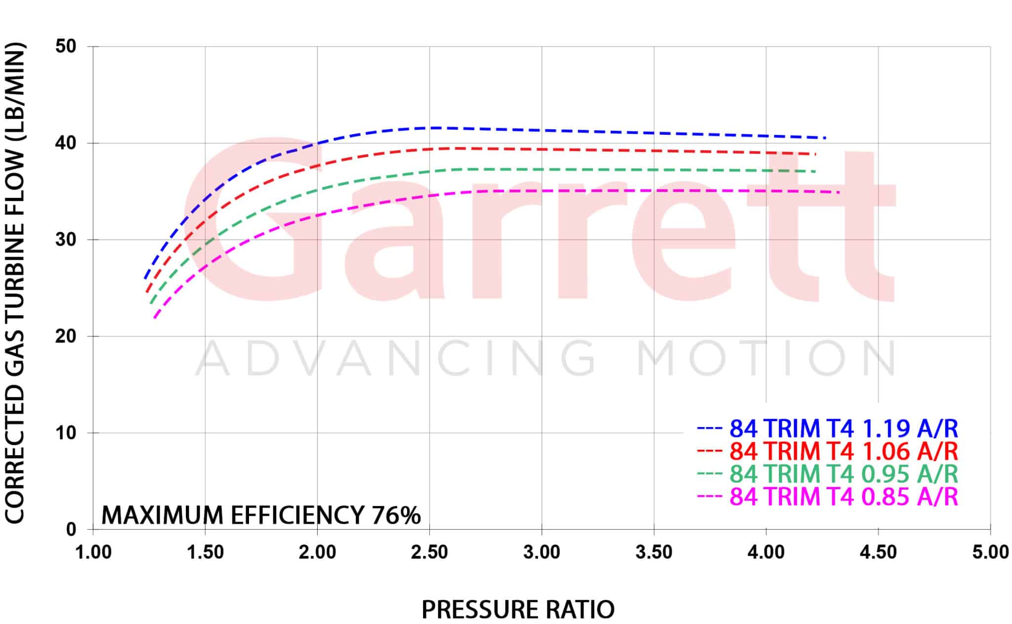
In addition to the wide compressor efficiency range, the G40 turbine reaches as low or lower than the G35 turbines at the far left of the low Pr range (about 22 - 23 lb/min @ 1.3 Pr for the 0.85 AR T4, about equal with the G30 1.01 AR VB Brettus is using!), yet it also outflows sooner and greater than the G35 1.06 AR T4 turbine (the only G35 divided T4 choice) from there as well. The G40-900 looks like it has a lot of rotary potential for a 450 - 600 whp top end, but how responsive you want it to be on the low end, fuel type, porting, etc. etc. is all going to matter. Those are my thoughts any way, not really so much intended as specific advice for your situation. The G40 release just came out a day or two before I posted about it, so perhaps some people were not so aware of the choice.
So I'm looking at the g40-1150, and according to my crappy math and minimal understanding of turbos/turbo math, I should be able to get about 655 at the tip of the center island at around 3.2, and about 717 at the end of the second with 3.6 ish on rotary(if I'm reading the map correct), and with the more aggressive trim of the g-40 I should be able to not have a ton of low end lag, my overall goal of the car is 6-700 depending on tune of the car, Id only do a decent size street port so I don't shake like hell off a stop light, fuel id assume e85, and I'm not terribly worried about lag, because if I really want to get rid of it ill just run a bit of anti-lag. 1 question however, how much does the different A/R change the efficiency of the turbo, and which would better match for a 2 rotor with moderately low lag. garrett offers A/R. 0.85 A/R | 0.95 A/R | 1.06 A/R | 1.19 A/R
G40-900 in the 0.95 A/R is looking pretty good..... I think I would go for that over the G35-900 in the 1.06 A/R, both divided/twin scroll. I think the G40 0.85 A/R may be a bit on the small side with regards to getting max efficiency. Just going off gut feel. The 76% peak turbine efficiency of the G40-900 is about as good as you'll ever see without some additional high-cost modifications like extrude hone of the housing; which housing(s) hit this peak number, only Garrett knows. That high turbine efficiency will offset some of the lag from the higher flow of the G40 turbine/housing combo compared to the G35-900. That peak efficiency is really good. The old GTX stuff is only like 70% peak efficiency. More turbine efficiency means faster spool and less back pressure. The old GTX4088R only had T4 divided housings. It was a really fun street turbo for something like a 2JZ. It was more popular on diesels trucks which commonly came with T4 divided flange turbine housings stock, like Cummins and old DMax.
I wonder if it’s too late to cancel my order for the g35 1050 I just ordered🤦🏻♂️
If you went with the T4 twin-scroll setup, I'd consider swapping to the G40-1150. That said, the G40-1150 is a step size larger in both comp and turbine. So it will come on later. Interesting that Garrett made the G40-900, but then jumped to G40-1150 which skips over the G35-1050 in compressor flow. If you're targeting power that's better suited to the flow of the G35-1050 compressor, well, the G40-900 will just be too small.
Last edited by spdracerUT; Nov 28, 2021 at 11:15 PM.
been sitting back rather than voicing my disagreement on certain comments, but you might want to check out that Rob Dahm is (likely) on the way to a 700whp 13B with a G35-1050 v-band on the Corvette swap. Wish he had done the divided T4 instead, but the v-band did allow for a clean piping configuration.
been sitting back rather than voicing my disagreement on certain comments, but you might want to check out that Rob Dahm is (likely) on the way to a 700whp 13B with a G35-1050 v-band on the Corvette swap. Wish he had done the divided T4 instead, but the v-band did allow for a clean piping configuration.
I actually shot Rob a message as soon as the G40 info dropped. Of course, he had just finished his G35-1050 build before SEMA and Garrett drops the G40 at SEMA. Looking at the turbine flow charts, the G40 divided 0.95 A/R flows about the same as the G35 1.21 A/R v-band Rob is using (I recall him using the biggest 1.21 option). Looking at the compressor maps, the G40-1150 surge line is only slightly to the right of the G35-1050 compressor. Rob could go to the G40-1150, go with a higher flowing 1.06 A/R divided housing, and have same spool-up as the G35-1050 but more power. Maybe even spool up a little better because of the combination of being divided vs open, and having higher turbine efficiency too. Of course, the G40 is physically larger, so tougher to package.
I actually shot Rob a message as soon as the G40 info dropped. Of course, he had just finished his G35-1050 build before SEMA and Garrett drops the G40 at SEMA. Looking at the turbine flow charts, the G40 divided 0.95 A/R flows about the same as the G35 1.21 A/R v-band Rob is using (I recall him using the biggest 1.21 option). Looking at the compressor maps, the G40-1150 surge line is only slightly to the right of the G35-1050 compressor. Rob could go to the G40-1150, go with a higher flowing 1.06 A/R divided housing, and have same spool-up as the G35-1050 but more power. Maybe even spool up a little better because of the combination of being divided vs open, and having higher turbine efficiency too. Of course, the G40 is physically larger, so tougher to package.
What did you message him on? And I ended up getting a g35-1050
I actually shot Rob a message as soon as the G40 info dropped. Of course, he had just finished his G35-1050 build before SEMA and Garrett drops the G40 at SEMA. Looking at the turbine flow charts, the G40 divided 0.95 A/R flows about the same as the G35 1.21 A/R v-band Rob is using (I recall him using the biggest 1.21 option). Looking at the compressor maps, the G40-1150 surge line is only slightly to the right of the G35-1050 compressor. Rob could go to the G40-1150, go with a higher flowing 1.06 A/R divided housing, and have same spool-up as the G35-1050 but more power. Maybe even spool up a little better because of the combination of being divided vs open, and having higher turbine efficiency too. Of course, the G40 is physically larger, so tougher to package.
The G40 plot is a divided T4, and the G35 plot is a v-band plot. So then you expect that the G35 v-band plots to fully represent what can be expected from the G35 divided T4?
Because what I would expect is a similar characteristic as we see on the G40 divided T4 plots, but reflecting the size difference between it and the G35. My thoughts on it extend more to the -900 compressor comments though, which I should have clarified better. For 700+ whp I agree the G40 makes sense, though it seems that some people throw that number out possibly without fully understanding what it is they really want or need. Which obviously choosing a 1.21 A/R housing means not looking for the best low end response. I really question needing 35+ lbs/min turbine flow for a 550 - 600 whp 13B short of an all out drag car or PP intake trying to avoid any negative emap.
The G40 plot is a divided T4, and the G35 plot is a v-band plot. So then you expect that the G35 v-band plots to fully represent what can be expected from the G35 divided T4?
.
No, hard to tell what the G35 divided T4 flows, completely different family/style of castings. But as Rob is using the v-band open volute 1.21 A/R, that turbine flow plot is a valid comparison to the G40 T4 divided flow plots.
Originally Posted by TeamRX8
Because what I would expect is a similar characteristic as we see on the G40 divided T4 plots, but reflecting the size difference between it and the G35. My thoughts on it extend more to the -900 compressor comments though, which I should have clarified better. For 700+ whp I agree the G40 makes sense, though it seems that some people throw that number out possibly without fully understanding what it is they really want or need. Which obviously choosing a 1.21 A/R housing means not looking for the best low end response. I really question needing 35+ lbs/min turbine flow for a 550 - 600 whp 13B short of an all out drag car or PP intake trying to avoid any negative emap.
but maybe I'm wrong.
.
The divided T4 housings of the G40 give them a spool-up benefit over the open volute v-band housings of the G35 where they have similar flows which is really only with the big open volute G35 v-band housings and the smaller A/R T4 divided housings of the G40. Given the same turbine flow vs pressure ratio characteristics, the divided housing will spool up better because it effectively increases turbine efficiency at the lower turbine flows. Better exhaust pulse energy utilization is another way to put it.
As a generalization having played around with modified cars for two decades, everyone likes to chase the big power number until they actually have to drive it on the street and have a lag monster which takes away the fun in most daily driving situations. No doubt about it, G35-1050 and G40 are BIG turbos. Definitely caters to a smaller crowd. They are necessary for people doing sustained high power runs though to keep the EMAP down. For the person just doing a quick burst on the street, they can probably push the EMAP higher a bit and get the benefit of better spool with a smaller turbine section; they won't be spending much time at high EMAP where heat soak and damage can be done.
Last edited by spdracerUT; Dec 3, 2021 at 01:55 PM.
Using an open scroll turbine housing on a 13b seems a huge mistake to me . If we want to try and replicate EFR esq results with the G series ..... they must be twin scroll.
But looking at the options for the G35 I see the 1.06 is still the largest available so ...enter the G40.
yes, but don’t overlook that the G40 divided T4 0.85 turbine plot starts at the same Pr-flow point as the G30 v-band 1.01 turbine plot.
Remember that T4 vs V-band discussion we were having? That was what I had been told by a very knowledgeable source and was trying to convey to you. They’re not going to be the same starting point or shape transitioning up to about 2.0 -2.5 PR.
spdracer, I concluded that we don’t disagree, but are expressing it differently
Well, to be fair... for a long time, open volute was the main option with aftermarket turbos going back to the old Garrett GT days and T3 flanged turbine housings
Personally, I'd do G35-900 with the T4 divided 1.06 if looking for an above moderate power level. I'd use G30 for a fun street turbo. For high power level, G40-1150.
Twin-scroll housings basically give a big turbine efficiency boost in the lower flow/PR area where a turbo is spooling up. This doesn't show on real turbine maps and their efficiency curves because those are generated on a steady state flowing gas stand. In the real world, IC engines are pulsating devices. When doing a turbo simulation, one adds turbine efficiency in the low end flow area to replicate the real world effects of using a twin-scroll housing. The effective turbine efficiency boost from twin-scroll is at a max at low flow/expansion ratio and basically disappears at high turbine flow/expansion ratio relative to an open volute housing. But there can still be benefit in reducing the cross contamination of exhaust on piston engines during overlap of exhaust valves from different cylinders being open at the same time. A 3-cylider engine never has the exhaust valve opening overlap. So you'll see inline-6 engines using a single twin-scroll turbo that basically breaks the engine up into a pair of 3-clyinder engines.
Anyway, when loading up the Borg Warner Matchbot, their default values actually show the turbine efficiency boost they are using to capture the real world pulsation effect. Look at how the turbine efficiency starts at 75% at low engine speed/turbine flow/expansion ratio and then drops down to 70% at high engine speed. I will guarantee you the gas stand map shows between 65%-70% at the low turbine expansion ratios. But for these spreadsheet type turbo matching techniques, one replicates the pulsation effect by increasing the turbine efficiency. Open volute has pulsation effect too, but twin scroll is much more significant which is why they spool up quicker. So at this first data point with the default setting of 75%, we will just assume that's for an open volute housing. Using a twin-scroll, you could bump that up to 80% as an approximation. Each engine and exhaust manifold setup has different pulsation characteristics, so if one where to do a more thorough turbo matching, you'd need real world engine data with a turbo that you had the compressor and turbine maps for and do a correlation to determine the pulsation characteristics of the particular setup. Then one could start plugging in different sized compressor/turbine wheel pairs and do all the performance simulation.
Or one could get fancy and plug all the 3D data into GT-Power and it can figure out all the pulsation. Though still good to do a correlation once real world data is available.
yeah, that’s why I question needing 35+ lbs/min for 550-600 whp in a 13B
because having seen various configurations run through that software, unless BW has an exclusive on the secret turbine efficiency sauce it’s going to be down closer to the G35-900 and G30-900 1.06 divided T4 flow range.
Working on getting a g40 900 for the 10ae. And definitely t4. I lost so much response on the v band. 750 rpm ish. I would love to compare the two setups. I mean the power is actually pretty linear compared to my other cars. And fun as hell on the street. Even though the rotary corvette sounds like complete **** it hauls ***. Surprised me to be honest. But I want the 10ae to be a fun track car. That compressor efficiency at 2 PR (14psi ish) had me excited to do stupid things like run the stock intercooler haha.
as we know, the rotary creates greater pressure impulses than a 4 cycle piston engine. this works (can be exploited) both on the intake as well as the exhaust side. consider the UIM design. from above we see two "U" shaped loops with a small plenum. front rotor intake port closes and Newton's Third Law enters the picture. for every action there is an opposite and EQUAL reaction. front rotor closes and charge air flowing at somewhere near Mach (Borg Warner) speed hits a brick wall and heads back through the U to an opening rear intake. the UIM "U" acts as an additional charge air multiplier. theory? yes, but proved out when i powderized a rear ceramic apex seal. there was as much of it in the front rotor as the rear.
the awesome peripheral 50 mm exhaust port is also capable of creating violent pressure force. no valve in the way. i prefer to harness the discrete impuses rather than dilute them with a V band.
now that Garrett is offering divided as well as advanced aero on the cold side i will be swapping out my 9180 for a G35-1050 and it will be fun to see comparative numbers including backpressure, temp out of the compressor etc. i still have fond memories for my GT4094r.
Last edited by Howard Coleman; Dec 7, 2021 at 05:11 PM.
as we know, the rotary creates greater pressure impulses than a 4 cycle piston engine. this works (can be exploited) both on the intake as well as the exhaust side. consider the UIM design. from above we see two "U" shaped loops with a small plenum. front rotor intake port closes and Newton's Third Law enters the picture. for every action there is an opposite and EQUAL reaction. front rotor closes and charge air flowing at somewhere near Mach (Borg Warner) speed hits a brick wall and heads back through the U to an opening rear intake. the UIM "U" acts as an additional charge air multiplier. theory? yes, but proved out when i powderized a rear ceramic apex seal. there was as much of it in the front rotor as the rear.
the awesome peripheral 50 mm exhaust port is also capable of creating violent pressure force. no valve in the way. i prefer to harness the discrete impuses rather than dilute them with a V band.
now that Garrett is offering divided as well as advanced aero on the cold side i will be swapping out my 9180 for a G30-1050 and it will be fun to see comparative numbers including backpressure, temp out of the compressor etc. i still have fond memories for my GT4094r.
that seems like a fairly large step down in turbine flow, surely a G35 would be a better match, especially if you are running a 6 speed, unless you want one turbo for autocross/khana and one for long track/standing distance events?
68% efficiency islands width at 20 and 30 psi for both turbos is approx 38 pounds wide, however the center of the G35 islands is 62.25/20 psi and 74.25/30 psi.
the 9180 centers are 51 and 60. lots more efficient flow from a smaller (almost 2 inches in length) package.
while the flow is biased higher, the G35-1050 starts at 23 pounds at 20 psi whereas the 9180 doesn't start to 30.3.
yeah, in addition to comments in the other active thread; perhaps some people are also either overlooking and/or underestimating the efficiency differences. The G Series are much more efficient in the peak operating range on the far right of the map. So much so that if the proper controls aren’t put into place the turbo will charge and overspeed right past the maximum compressor rpm limitation still making strong power rather than stalling out. Its that max rpm threshold that is limiting these turbos on max flow rather than efficiency falling off the cliff. More than a few people have damaged a G series compressor wheel over-revving them; the compressor wheel will start stretching under the excessive centrifugal loading and contacting the housing. Moreover, it’s the improved efficiency that is resulting in the smaller diameter wheels performing like larger ones.
Credit for Howard C. and his insightful posts over the years that have led and bred my understanding to where it is today. I walked in his footsteps to get here.
.
Garrett must have recently added 'v band' housings to the G40 range. Interesting to see the difference between the 'v band' and T4 . Flow differences could be due to friction from the twin scroll divider or perhaps the 'v band' has a higher cross sectional area. Any thoughts on this ?