When you click on links to various merchants on this site and make a purchase, this can result in this site earning a commission. Affiliate programs and affiliations include, but are not limited to, the eBay Partner Network.
I feel for you. Even living here in the DFW metroplex area I can't hardly get anyone to answer their phone, call me back, or the few I did talk with to commit to an appointment I can count on just trying to get an hour or two of dyno time. I don't see it getting better any time soon either.
.
that�s crazy, especially in that location! I hope we can catch a break soon, hopefully winter-ish weather they will slow down and we can get some responses. good luck to ya
Honestly you're likely to be just fine with the full-race one. I got the engine flanges and merge collector from Glease/Roiel and the shop doing my build fabbed the rest.
I guess the better WG placement is close to the turbine housing. My shop extended the WG neck a few inches away. When I asked why so far they said that they experienced premature failures in the WG's of their landspeed record car when the WG's were too close in. Knowing I want to turn this into a streetable track car (emphasis on track car) they took the extra precaution. I claim no real expertise, but I'd honestly think the full-race one is fine unless you REALLY want to punish your engine bay.
Mine for reference:
holy Hannah!!! That is one mean looking set up, the rerouting of the DWG�s is impressive. If I had a fab shop I felt could tackle a job like that I wouldn�t be so worried, that and I am building this in the garage with my son so the more parts that don�t require fab work etc the better. I�m torn between turblown cast and the full race�I do like how I can get the turbo kit from turblown so all I�ll really have to worry about after all that is fuel &ignition until the pfc can be replaced.
Thats the one I made in 2015 for the 8374EFR IWG.
Spools inpressive, better than stock ( may also be because of exhaust porting )
But gives you a litte boostcreep at 6500, I can give you graphs or numbers if you like.
By design what Turboblown made with the Turboblown Cast EFR IWG manifold should be quite the same
how bad was the boost creep. what psi did it creep up to? can you post some graphs. thanks
how bad was the boost creep. what psi did it creep up to? can you post some graphs. thanks
It was not bad at all, Ive got the low boost IWG, which opens at like 6-7psi but boost creeped to 10psi
My target was to start with 10psi and later go up to 14psi.
The boost controller in my haltech didnt work properly which I didnt realise because I had the boost I wanted. :P
This it what it looked like in my very first run with the EFR (boost vs. rpm):
But boost creep can always be different, it depends a lot on air temps and so.
One time at a hill climb race I had high intercooler temps because of long waiting before the start, and there was no boost creep at all.
I ran with constant 6psi up the hill...this was when I first realized I had no boost control XD
I also had a run on the racetrack when my wastegate actuator came loose.
So WG was basicly open all the time and boost still creeped up to about 10psi at 6500, but I cant find the log data right now...
on the post above; high IATs could mean the tuning is cutting back engine performance for safety considerations, resulting in less power output. This may in turn result in less flow through the exhaust and then lessening the tendency to creep?
.
It was not bad at all, Ive got the low boost IWG, which opens at like 6-7psi but boost creeped to 10psi
My target was to start with 10psi and later go up to 14psi.
The boost controller in my haltech didnt work properly which I didnt realise because I had the boost I wanted. :P
This it what it looked like in my very first run with the EFR (boost vs. rpm):
But boost creep can always be different, it depends a lot on air temps and so.
One time at a hill climb race I had high intercooler temps because of long waiting before the start, and there was no boost creep at all.
I ran with constant 6psi up the hill...this was when I first realized I had no boost control XD
I also had a run on the racetrack when my wastegate actuator came loose.
So WG was basicly open all the time and boost still creeped up to about 10psi at 6500, but I cant find the log data right now...
my motor is street port also. i ordered the Turblown EFR 8374 IWG kit and will be running Haltech 1500. so pretty much similar setup as your, which is why i asked. but 10 psi boost creep is not bad. i do want the ability to turn it down as much as i can if i decide to take the car on road course. interesting that the boost creep taper down after 6k tho. usually boost creep is a run away train and keeps going up. my current setup has boost creep past 14 psi, so i end up running a 2.75" restrictor plate in a 3" exhaust to keep the boost creep down. it's a greedy style manifold, i guess the WG port cant flow enough for street port engine.
holy Hannah!!! That is one mean looking set up, the rerouting of the DWG�s is impressive.
Originally Posted by iceman4357
Wow, that is a hell of a fab job.
Thanks guys! I can't take any credit for it though, that all goes to the shop (5523 Motorsports).
Originally Posted by TeamRX8
missed this previously; just curious why?
.
Unfortunately I don't know the science behind the "why" of it. I just know that, according to TurboSmart, the best location is as close to the turbo as possible and with a favorable transition angle.
I'd assume it's a combination of less turbulence, reduced likelihood of excess gas heading towards the turbo (cohesion), and perhaps response effectiveness?
on the post above; high IATs could mean the tuning is cutting back engine performance for safety considerations, resulting in less power output. This may in turn result in less flow through the exhaust and then lessening the tendency to creep?
.
If it pulls timing there will be more exhaust energy from the same mass flow. It's almost certainly just a result of lower intake density = less mass flow = less exhaust flow and energy, especially if some elevation above baseline is involved too.
my motor is street port also. i ordered the Turblown EFR 8374 IWG kit and will be running Haltech 1500. so pretty much similar setup as your, which is why i asked. but 10 psi boost creep is not bad. i do want the ability to turn it down as much as i can if i decide to take the car on road course. interesting that the boost creep taper down after 6k tho. usually boost creep is a run away train and keeps going up. my current setup has boost creep past 14 psi, so i end up running a 2.75" restrictor plate in a 3" exhaust to keep the boost creep down. it's a greedy style manifold, i guess the WG port cant flow enough for street port engine.
Yeah it is not a really big thing, and with boost creep dropping back till 7000 it still feels controlable.
Ive got a bridgeport but I also dont know why it is dropping back, but I also had some strange noise from 6000rpms on, sounds like flow dependent.
Thats also why I made the custom intake manifold, lets see what difference this will make ( in boost creep and noise )
Originally Posted by Slides
If it pulls timing there will be more exhaust energy from the same mass flow. It's almost certainly just a result of lower intake density = less mass flow = less exhaust flow and energy, especially if some elevation above baseline is involved too.
Thats exactly what I think, the engine protections arent that big in my mapping at this point of the IAT.
In boost creep your boost is not controlled anymore and can be affected by the slightest changes.
My opinion is also, what gives you more power also results in more boost creep...
Unfortunately I don't know the science behind the "why" of it. I just know that, according to TurboSmart, the best location is as close to the turbo as possible and with a favorable transition angle.
I'd assume it's a combination of less turbulence, reduced likelihood of excess gas heading towards the turbo (cohesion), and perhaps response effectiveness?
Thank you for taking the time to explain it. However, that seems like possibly a misinterpretation to me. Because the typical 13B as well as your own manifold differ in that there is no collector (possibly go back and read the specifics of the example being provided in the link), but two individual pipes feeding directly and independently, each into a separated port of a twin scroll turbine, and each pipe with it�s own wastegate. The pipes on this manifold are not so long, and this particular point is not likely that great, but on a manifold with longer pipes the WG placement at the turbine then results in all the flow having to go through those pipes before dumping off the excess flow. If the WGs are instead positioned as close to the exhaust port as possible, then it�s instead dumping the excess off early and only flowing the lesser amount of exhaust energy up the pipes to the turbine.
Understand that backpressure results from the amount of flow in a pipe coupled with it�s diameter, length, turns, etc. By routing all the flow all the way up to the turbine; rather than dumping the excess off sooner and only flowing the lesser amount needed through them, is potentially resulting in more emap at the exhaust port/engine. So in the case of longer pipes of smaller ID this is going to come more into play. Again, the exhaust pipes aren�t that long on this particular manifold, but as nice of a fab job as it is, what I see is that placing the WGs at the turbine results in not just extra fabrication effort and cost, but also the long contorted paths of the WG pipes is radiating a lot of heat energy up higher in the engine bay and in close proximity of the intake manifold. As opposed to the WGs and their shorter, less contorted pipe routing being positioned down close to the exhaust ports, lower in the engine bay, underneath the manifold, and away from the intake manifold.
It�s not intended as a criticism, but just my observation based on those principles.
Because wrt the linked article, when there are say four pipes feeding into a collector and the collector feeding into the turbine, then what was proposed makes sense. If you have the WG positioned close to where the multiple pipes enter the collector, then it may favor only the flow of the closest pipes to it, which is going to bias total collected flow to the turbo rather than the WG. Putting it closer to the turbine as presented then helps to avoid that situation and puts the WG in a better position for the flow of all the pipes to have access to the WG. So again, in the case of only two exhaust pipes; each with it�s own wastegate, it�s not the same thing. Most collectors aren�t as long and snaking around as some 13B exhaust pipes are. If they were though, then imo the same thing would apply; placing the WG position earlier in the collector, but not too close to where the multiple pipes enter and biasing it to only part of the flow, would be preferred rather than at the far end at the turbo. There are other factors though; space constraints and such, which might limit where the WG has to be. Looking at your manifold though, there seems to be room down low for dual WG placement.
in the case of a 13B with dual WGs and twin scroll, and depending on the power goal, it could be argued that having 2� pipe exiting the port to the WG and then reducing down after it with 1.5� to the turbine would be preferred. I don�t share in the ideas I�ve seen presented about the piping length between WG and turbine.
that�s how I see it anyway feel free to voice counter/opposing views
.
i tend to agree with that logic. since having separate runner and WG for each of the twin scroll, the exhaust pressure should be same on both side. pressure is going to travel the path of least resistance and getting that excess pressure out sooner rather than later is probably more efficient.
I see no fault in placing the WG close to the turbo, because exhaust temps may drop on the path from the exhaust port to the turbo.
So first the WG sees lower temps, and second the WG sees the same temps thus density (maybe even pressure ) as the turbo, so boost control may be more consistent.
Otherwise it may give you varying boost (or at least WG duty) for hot and "cold" exhaust.
Just my idea...
Thank you for taking the time to explain it. However, that seems like possibly a misinterpretation to me.
that�s how I see it anyway feel free to voice counter/opposing views.
It's entirely possible that ideal WG placement is different for a rotary application. As I said, I'm not sure of the science behind the why so all I can do is speculate on the reasons.
Marty's statement of "The ideal location for the wastegate is as close to the turbine housing as possible, and in a manner that provides a good flow path into the wastegate" is pretty cut and dry though.
Obviously it isn't the end of the world to have the WG's right at the exhaust ports, plenty of folks have done it without catastrophic failures. That would definitely be an interesting test to run though, comparing two manifolds back to back with the only variable being the location of the WG runners.
My experience with locating the WGs close to the exhaust port VS close to the turbo (so talking either end of exhaust runners) is that it all affects boost control.
Boost control is the primary function for the WG.
_____
On the peripheral exhaust port rotary application, WG position closer to the turbo makes high rpm boost creep more likely.
In the higher RPMs there is a higher volume of exhaust gas by the time it travels to the wastegate/turbo because peripheral exhaust port rotaries have plentiful external combustion in the higher RPMs.
The higher volume of exhaust gas further from the exhaust port means higher velocity per given runner diameter, so WG priority/size is even more important.
*Aside- this is also why long runner exhausts are preferred on a big turbo rotary. Get big turbo spooled sooner (but remember big turbo spooling in the high rpm range unlike a smaller turbo which spools in low rpm range where external combustion effect is not as strong).*
_________
WG close to rotary peripheral exhaust port makes high rpm boost drop off more likely.
Dynamic exhaust manifild pressure is much higher near the exhaust port (not talking about a static/time weighted average pressure). These high pressure pulses pushing on the bottom of the WG poppet valve tend to keep the WG valve open in the higher RPMs. Its WG valve float.
*Aside- these dynamic high pressure pulses near the exhaust port are what can help spool a smaller turbo in the low RPM on a rotary and Mazda developed straight bladed "impact" turbines with Hitachi to maximize the affect.
______
So, like everything else; WG position is a balance in my experience.
But your recommention towards longer runners only counts for PP engines?
Because I thought shorter is better for spool to make use of the exhaust pulses ( in twin scroll )
Or is a 8374 already considered a small turbo on a 13B ?
Peripheral exhaust port rotaries (1967-2002 engines).
Yeah, 8374 is a small turbo on a rotary that spools in the low rpm and will benefit from short runners for spool.
Large turbos are the T6 flanged 1,000+ hp turbos that drag racers have typically used on the rotary and cant/dont spool below 5,000rpm.
Road racers may sometimes use long runner manifolds with small/medium frame turbos to lower exhaust manifold pressure for reliability at the expense of spool/response.
Typically long/medium runner manifolds are most popular just to fit a decent sized turbo in the narrow FD engine bay.
The same reason you need a big turbo for a PP exemplifies the counter reason it won’t work if there is too much flow restriction through the engine. In that case the way-big turbo is too restricted and before the engine can get going fast enough to let the flow through then it will just back up into the compressor inlet, i.e. lag.
Except in the situation below I don’t think it’s been recognized yet that it’s not just the IC, but *everything* downstream of it too
Good I have a small turbo then bc I do race on circuit
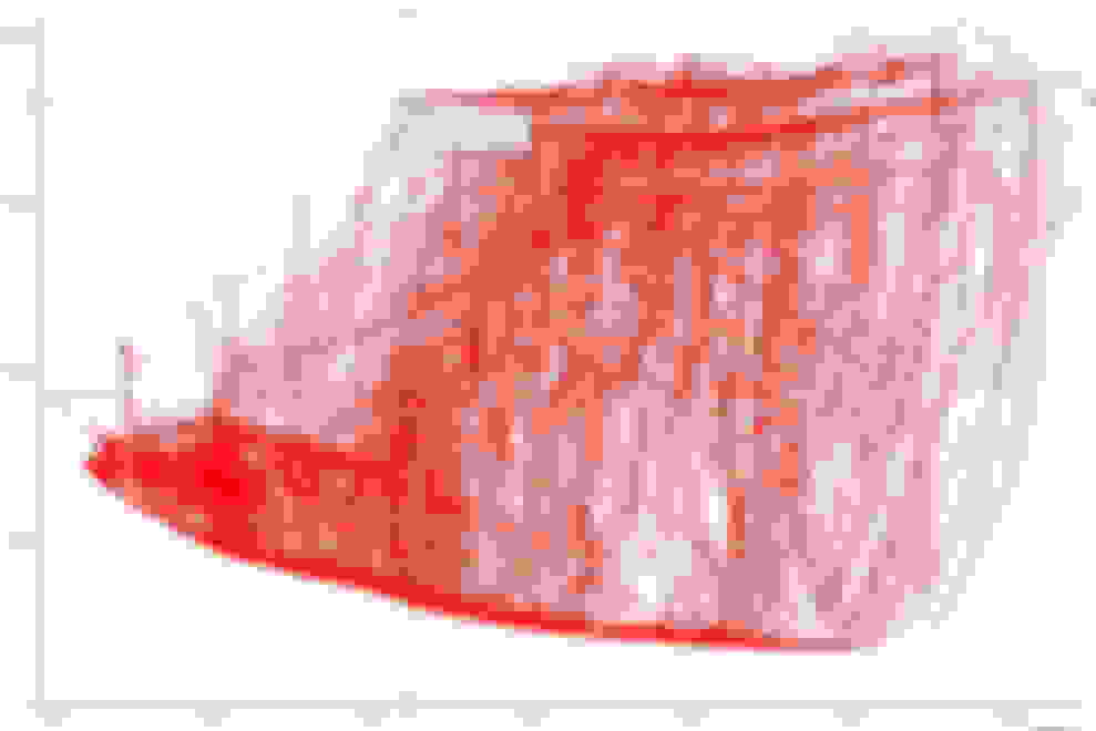
Last year I was mapping my new CNG secondaries on an abandoned soviet air field
and to trigger the secondaries on my haltech I pressed gas and brakes to build ealy boost.
You can see the vertical lines at 1500, 2000 and 2500
Later I did some spool tests in 4th gear, where I reached target boost ( 1800mbar ) from 3200.
And in normal racing, full boost is there from 3600 on
For circuit racing this is perfect for me, I'm normally not reving below 3500.
For drag racing this may be not necassary to have this early spool, and for street driving it's maybe to laggy for some people...


 feel free to voice counter/opposing views
 ) as the turbo, so boost control may be more consistent.