
Rotary Peak Pressure Location ATDC

Thread Starter
"Elusive, not deceptive!�
Joined: May 2007
Posts: 930
Likes: 13
From: Slidell, LA
Very cool.
I'm not very knowledgeable about this, but someone with Champ Car experience once told me that it would be wise to adjust fuel and timing for best output power on a dyno, and measure peak pressure location to get some data showing how fuel, timing, and peak pressure relate to output power. What I took away from it was that piston guys can change engine geometry (compression ratio, bore, stroke) (and rod ratios as Speed of Light was referring to) in enough ways that the ideal peak pressure location may not be the same for every setup. With luck, the variance between rotary setups will be less since we have less control of the geometry (can swap rotors to change compression ratio, but that's about it?).
I think the only thing we could change easily would be the rotor pocket.
According to Mazda's research moving it rearward would introduce the squish later changing burn characteristics.
The same person also claimed that peak pressure is very useful to know, but average pressure during the combustion cycle is also important. For instance, a high-compression + low-boost engine may see X PSI peak pressure, but a low-compression + high-boost engine may see the same peak pressure but a higher average pressure (this I don't completely understand)... and therefore more power output during the combustion stroke. That may be going off on a tangent, however.
On this system they chart Indicated Mean Effective Pressure (IMEP) on another data selection page.
Barry

Full Member
Joined: Feb 2010
Posts: 63
Likes: 0
From: New Zealand
Yes only really a incylinder pressure transducer can indicate IMEP (as far as im aware anyway) as a engine dyno factors in friction mean effective pressure(FMEP) + IMEP which equates to BMEP
Very interesting barry
Rotary Enthusiast
Joined: Jun 2004
Posts: 862
Likes: 0
From: Austin TX.
HEY Barry,, that graph looks like TFX.engine@yahoo.com
did you look at there graph for an NA nitro engine, over 4000psi cyl.pressure.
somethin like 400hp per cyl.,, that equates to around 3200hp on an 8 cyl. engine. NA
now if we could just make 1000hp per rotor!!!
what will you do once you get the information you are lookin for??
did you look at there graph for an NA nitro engine, over 4000psi cyl.pressure.
somethin like 400hp per cyl.,, that equates to around 3200hp on an 8 cyl. engine. NA
now if we could just make 1000hp per rotor!!!
what will you do once you get the information you are lookin for??
Thread Starter
"Elusive, not deceptive!�
Joined: May 2007
Posts: 930
Likes: 13
From: Slidell, LA
HEY Barry,, that graph looks like TFX.engine@yahoo.com
Yes Ron it is a TFX system. Their website has great explanations of all the functions.
http://www.tfxengine.com/index.html
Did you look at there graph for an NA nitro engine, over 4000psi cyl.pressure.
somethin like 400hp per cyl.,, that equates to around 3200hp on an 8 cyl. engine. NA
now if we could just make 1000hp per rotor!!!
what will you do once you get the information you are lookin for??
Mazda and aftermarket companies have done all this testing already but between the language barriers
and small companies� profit needs not much of the results are trickling down to us.
Dyno testing may arrive at the same conclusions but wouldn't it be interesting to see what is going on inside the engine.
The next step would be to add sensors of lower pressures to the intake and exhaust ports for a little tuned length/overlap understanding.
Barry
My thought is that we have too little ongoing rotary engine research that is shared.
Mazda and aftermarket companies have done all this testing already but between the language barriers
and small companies� profit needs not much of the results are trickling down to us.
Dyno testing may arrive at the same conclusions but wouldn't it be interesting to see what is going on inside the engine.
The next step would be to add sensors of lower pressures to the intake and exhaust ports for a little tuned length/overlap understanding.
Barry

Thread Starter
"Elusive, not deceptive!�
Joined: May 2007
Posts: 930
Likes: 13
From: Slidell, LA

This is what the combustion looks like.
The red line is the pressure of rotor compression without ignition.
The blue line is ignited pressure.
The purple line is the temperature of the burning mixture. Notice it is still 1400�C when the exhaust port opens.
The pressure at exhaust port opening (EOP) is 91 psi.
A detonation rating of 65/88/0 shows up for this #64 cycle. Since it has 0 frequency I am assured by the Mentor that it is benign. (But whenever the peak pressure is advanced below 45� it gets some of these readings.)
The HP and torque readings are off in this sample because I am using the wrong displacement calculations (400cc vs 650cc).
Barry
Thread Starter
"Elusive, not deceptive!�
Joined: May 2007
Posts: 930
Likes: 13
From: Slidell, LA

More interpretation.
The red arrows indicate an engine misfire (in this case the mixture was too rich) .
The blue arrows depict a too retarded cycle at about 60� with subsequent lower pressure.
The green arrow show a cycle closer to 45� and higher pressure.
I am amazed at the scatter.
Barry
Thread Starter
"Elusive, not deceptive!�
Joined: May 2007
Posts: 930
Likes: 13
From: Slidell, LA
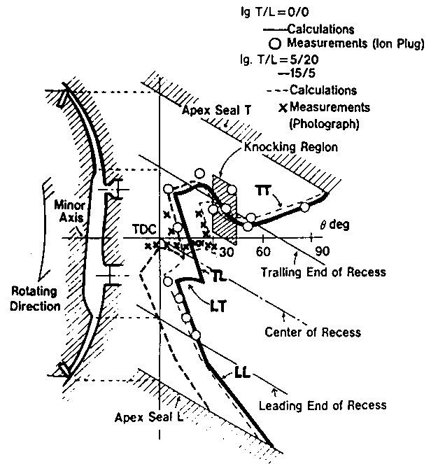
There are a lot of concepts to interrelate when considering what is going on inside of a rotary engine.
This is from a Mazda paper Rotary86v6a4, Fig. 14, showing flame propagation.
I think this is probably Mazda Research at its best!
If you haven't seen it before please take your time trying to understand it.
Some things to note:
Because the mixture is flowing the flame front hardly moves upstream at all. In fact the trailing portions of both flame patches are pushed backwards part of the time.
The squish generation and trench shape further complicates this movement.
When the leading and trailing flame fronts collide (at about 20� ATDC) that their speed diminishes.
The knock region is from 30� - 45� ATDC and where the knock sensor is located.
Barry


Barry, can you link us to high resolution screenshots of your graphs? Those are tough to read.
The collision of the leading and trailing flame fronts is very important. It is a main cause of the quenching problem in these engines. It's one of the main things Mazda is changing with the 16X engine (look up the patent document and read it). On the new engine the leading and trailing plugs are farther apart and the combustion chamber is physically thinner. This gives the two flame fronts more time to burn before colliding.
Mazda found that the flame fronts travel slowly towards the side housings but quickly toward each other. That's why they could make the chamber thinner and spread the plugs out to give more burn time.
Thread Starter
"Elusive, not deceptive!�
Joined: May 2007
Posts: 930
Likes: 13
From: Slidell, LA
Barry, can you link us to high resolution screenshots of your graphs? Those are tough to read.
The collision of the leading and trailing flame fronts is very important. It is a main cause of the quenching problem in these engines. It's one of the main things Mazda is changing with the 16X engine (look up the patent document and read it). On the new engine the leading and trailing plugs are farther apart and the combustion chamber is physically thinner. This gives the two flame fronts more time to burn before colliding.
Mazda found that the flame fronts travel slowly towards the side housings but quickly toward each other. That's why they could make the chamber thinner and spread the plugs out to give more burn time.
The collision of the leading and trailing flame fronts is very important. It is a main cause of the quenching problem in these engines. It's one of the main things Mazda is changing with the 16X engine (look up the patent document and read it). On the new engine the leading and trailing plugs are farther apart and the combustion chamber is physically thinner. This gives the two flame fronts more time to burn before colliding.
Mazda found that the flame fronts travel slowly towards the side housings but quickly toward each other. That's why they could make the chamber thinner and spread the plugs out to give more burn time.
Raymond that is exactly how I understand it. But we can't move our plugs so we will have to do the best with what we have.
Wouldn't this be the reason why we use more split. We then keep the burn rate high by separating the with time interval to add to the physical dimensional spread to delay the collision.
I sent the original document to you. I am presently looking for the 16X paper to reread it.
Barry
Are you guys trying to figure out where the engine rotation is when the rotor has the most leverage on the eccentric shaft or where the chamber is when it is at max chamber pressure? Unfortunately these aren't at the same place. It would be nice if they were.
Joined: May 2005
Posts: 2,745
Likes: 0
From: North Bay, Ontario
Barry, for the first graph showing compression / combustion, was this a full throttle run? Also, what kind of manifold pressure / ignition advance lead to peak pressure at 45* atdc?
Rotarygod, is the ideal rotor positioning for leverage not at 45*? I believe that was the number Barry was aiming for to align the two by changing ignition advance. It seems that it also has made for the highest combustion pressure as well. Or am I missing the whole point of this?
Rotarygod, is the ideal rotor positioning for leverage not at 45*? I believe that was the number Barry was aiming for to align the two by changing ignition advance. It seems that it also has made for the highest combustion pressure as well. Or am I missing the whole point of this?
Thread Starter
"Elusive, not deceptive!�
Joined: May 2007
Posts: 930
Likes: 13
From: Slidell, LA
Neither are they in the same place on a piston engine.
My guess is that we are looking for the best spot to apply peak pressure... and does it change with RPM.
What are your thoughts?
Barry
Thread Starter
"Elusive, not deceptive!�
Joined: May 2007
Posts: 930
Likes: 13
From: Slidell, LA
[QUOTE=Barry Bordes;10049157]

Trots,
I guess reply #21 is the graph you are referring to. Yes it is WOT but part of section 1 is before the wastegate opening.
Just looking at this sample I would say add a degree to section 2 and two degrees to section 3.
Let me do more testing before making any carefully calculated decisions on what might reasonable timing for others.
I wouldn't want to destroy anyone's engine by hastily giving out unsubstantiated preliminary findings.
Also my engine is different and has its own issues. Right now at 8000 rpm I am running 1050�C EGT on the sensor sparkplug location front rotor.
Barry
Barry, for the first graph showing compression / combustion, was this a full throttle run? Also, what kind of manifold pressure / ignition advance lead to peak pressure at 45* atdc?
Rotarygod, is the ideal rotor positioning for leverage not at 45*? I believe that was the number Barry was aiming for to align the two by changing ignition advance. It seems that it also has made for the highest combustion pressure as well. Or am I missing the whole point of this?
Rotarygod, is the ideal rotor positioning for leverage not at 45*? I believe that was the number Barry was aiming for to align the two by changing ignition advance. It seems that it also has made for the highest combustion pressure as well. Or am I missing the whole point of this?
I guess reply #21 is the graph you are referring to. Yes it is WOT but part of section 1 is before the wastegate opening.
Just looking at this sample I would say add a degree to section 2 and two degrees to section 3.
Let me do more testing before making any carefully calculated decisions on what might reasonable timing for others.
I wouldn't want to destroy anyone's engine by hastily giving out unsubstantiated preliminary findings.
Also my engine is different and has its own issues. Right now at 8000 rpm I am running 1050�C EGT on the sensor sparkplug location front rotor.
Barry
Too old for this
Joined: Oct 2009
Posts: 488
Likes: 0
From: Denver, CO
Barry, that flame front chart is really interesting. I can see how the negative split discussed here would work. If I'm reading that correctly, the flame doesn't reach the trailing apex until after 90�?
Joined: May 2005
Posts: 2,745
Likes: 0
From: North Bay, Ontario
Sorry Barry, I was referring to Post #33, I'm not trying to take a specific outcome and generalize it, but the characteristics of that combustion event show peak pressure at ~45* ATDC, which I thought was the ideal position.
Having said that, every engine, with slightly differing compression ratios, port timing, VE, intake charge temperatures, charge densities, ETC! will require different timing to achieve that, and will change at different RPM's (if that is even what we're trying to accomplish!) I was just wondering what it was, as far as boost, turbo, lead timing and split that got you there.
Having said that, every engine, with slightly differing compression ratios, port timing, VE, intake charge temperatures, charge densities, ETC! will require different timing to achieve that, and will change at different RPM's (if that is even what we're trying to accomplish!) I was just wondering what it was, as far as boost, turbo, lead timing and split that got you there.
Thread Starter
"Elusive, not deceptive!�
Joined: May 2007
Posts: 930
Likes: 13
From: Slidell, LA
Barry, that flame front chart is really interesting. I can see how the negative split discussed here would work. If I'm reading that correctly, the flame doesn't reach the trailing apex until after 90�?
I captured a few negative split logs but they need more study.
�the flame doesn't reach the trailing apex until after 90�"
If at all! This is because of the cooling effect of the large surface area of the combustion chamber. A good case for rotor coatings.
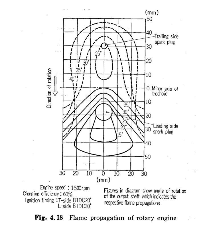
Here is another vertical view of what is happening. (from Yamamoto�s 1981 book)
Barry
Thread Starter
"Elusive, not deceptive!�
Joined: May 2007
Posts: 930
Likes: 13
From: Slidell, LA
Sorry Barry, I was referring to Post #33, I'm not trying to take a specific outcome and generalize it, but the characteristics of that combustion event show peak pressure at ~45* ATDC, which I thought was the ideal position.
Having said that, every engine, with slightly differing compression ratios, port timing, VE, intake charge temperatures, charge densities, ETC! will require different timing to achieve that, and will change at different RPM's (if that is even what we're trying to accomplish!) I was just wondering what it was, as far as boost, turbo, lead timing and split that got you there.
Having said that, every engine, with slightly differing compression ratios, port timing, VE, intake charge temperatures, charge densities, ETC! will require different timing to achieve that, and will change at different RPM's (if that is even what we're trying to accomplish!) I was just wondering what it was, as far as boost, turbo, lead timing and split that got you there.
The biggest problem in interpretation seems to be the �data scatter�. We will be required to tune for the most advance scatter points to keep from going into detonation.
One solution is to decrease the intensity of scatter. I have noticed that the one variable of AFR seems to decrease the extremes. My 12 psi test row is being kept as close to 11.3 AFR as possible.
Maybe better ignition may also smooth things.
Paul Yaw thinks better fuel atomization may help. My Bosch 1600 with resistors may be part of my high EGT problem.
So many tests to sink our teeth into.
Barry
Thread Starter
"Elusive, not deceptive!�
Joined: May 2007
Posts: 930
Likes: 13
From: Slidell, LA
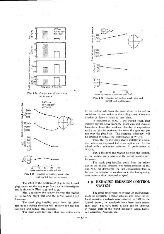
Comparisons on temp and fuel consumption plus emissions.
There is a better reference but it escapes me for now.
They seem to have tried to find the optimum for the 13B dimensions.
Barry
Thread Starter
"Elusive, not deceptive!�
Joined: May 2007
Posts: 930
Likes: 13
From: Slidell, LA
MadScience, check Yamamoto's 1981 book on plug placement. Page 52 Figs. 4.55 and 4.56.
Comparisons on temp and fuel consumption plus emissions.
There is a better reference but it escapes me for now.
They seem to have tried to find the optimum for the 13B dimensions.
Barry
Comparisons on temp and fuel consumption plus emissions.
There is a better reference but it escapes me for now.
They seem to have tried to find the optimum for the 13B dimensions.
Barry
Barry