
My New 60-1 / Custom manifold!

Thread Starter
Joined: Sep 2001
Posts: 932
Likes: 0
From: Altadena, CA
Hey guys!
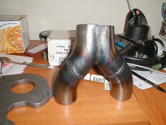
I just picked up a new TO4B 60-1 (.96 hotside, P-trim, 4" inlet, etc. etc.) a couple weeks ago. Over the last two days I've managed to bungle together (well, it's almost done ) an exhaust manifold that looks like it just might work too! I think I'll be able to keep the smog pump on there if all goes according to plan...
Anyway, I had a couple of questions for some of the gurus
The manifold is 1/8" thick mild steel. Several people have told me that this will probably not last too long, and if this is the case, I was wondering how mild steel manifolds usually fail? I found some really nice looking coatings on www.performancecoatings.com that'll take up to 2000* F, and I'd imagine that something like this would dramatically increase the life of the manifold. Am I on the right track here? I am planning to add some bracing between the flanges on the manifold (turbo --> exhaust, wastegate --> exhaust)
Anyway, any suggestions on the manifold / coatings, or insight into exactly how they usually fail would be great!.
I've heard that Crispeed uses mild steel manifolds. If you're reading this, CRISPEED, I don't suppose you could shed some light on the issue <thanks!>
Thanks in advance!,
Manolis
18 years old.... trying to catch up to a local 3rd gen by crhistmas time
I just picked up a new TO4B 60-1 (.96 hotside, P-trim, 4" inlet, etc. etc.) a couple weeks ago. Over the last two days I've managed to bungle together (well, it's almost done ) an exhaust manifold that looks like it just might work too! I think I'll be able to keep the smog pump on there if all goes according to plan...
Anyway, I had a couple of questions for some of the gurus
The manifold is 1/8" thick mild steel. Several people have told me that this will probably not last too long, and if this is the case, I was wondering how mild steel manifolds usually fail? I found some really nice looking coatings on www.performancecoatings.com that'll take up to 2000* F, and I'd imagine that something like this would dramatically increase the life of the manifold. Am I on the right track here? I am planning to add some bracing between the flanges on the manifold (turbo --> exhaust, wastegate --> exhaust)
Anyway, any suggestions on the manifold / coatings, or insight into exactly how they usually fail would be great!.
I've heard that Crispeed uses mild steel manifolds. If you're reading this, CRISPEED, I don't suppose you could shed some light on the issue
<thanks!>Thanks in advance!,
Manolis
18 years old.... trying to catch up to a local 3rd gen by crhistmas time
Rotary Enthusiast
Joined: Nov 2002
Posts: 1,021
Likes: 2
From: -
Re: My New 60-1 / Custom manifold!
Originally posted by Manolis_D
... Am I on the right track here? I am planning to add some bracing between the flanges on the manifold (turbo --> exhaust, wastegate --> exhaust)...
... Am I on the right track here? I am planning to add some bracing between the flanges on the manifold (turbo --> exhaust, wastegate --> exhaust)...
Senior Member
Joined: Aug 2001
Posts: 445
Likes: 0
From: houston
as long as you TIG weld it ( for lower heat) and brace the turbo to the engine. you should be ok, your runners are short so the header will be stronger than usual. .125 wall is plenty thick enough and since this is your first header i would not waste the time/money coating it until you are sure it is going to work, the coatings dont really add life to the header if it is fabricated incorrectly.
MWW
MWW
Trending Topics
Thread Starter
Joined: Sep 2001
Posts: 932
Likes: 0
From: Altadena, CA
Yup, same knife 
Thanks, I like it too
On another topic, anybody know if i'll have trouble with boost control if put the wastegate runner in the collector (right before the turbo flange)? How much on an angle does it have to have, or can it be almost 90*?
Thanks, and keep them comments coming!
Manolis
Thanks, I like it too
On another topic, anybody know if i'll have trouble with boost control if put the wastegate runner in the collector (right before the turbo flange)? How much on an angle does it have to have, or can it be almost 90*?
Thanks, and keep them comments coming!
Manolis
Originally posted by Manolis_D
On another topic, anybody know if i'll have trouble with boost control if put the wastegate runner in the collector (right before the turbo flange)? How much on an angle does it have to have, or can it be almost 90*?
On another topic, anybody know if i'll have trouble with boost control if put the wastegate runner in the collector (right before the turbo flange)? How much on an angle does it have to have, or can it be almost 90*?
The reason you want a more acute angle to flow to the WG is so when it opens, it acts like a more free-flowing exhaust (open header style).
Do your best, and don't worry if it's a 90. I have seen dozens that are 90's and they work fine.
If you want good Boost control, Ged a good large WG to avoid all the creep.
Senior Member
Joined: Sep 2001
Posts: 373
Likes: 1
From: California
Manolis, what nationality are you? Anyhow, as for your question, the reason the steel manifolds almost always crack is because of the heat up/cool down process where the metal expands/contracts. Most of the time with the bends or curves of the manifold runners, this expand/contract process creates pressure against itself, ie. one runner pushing in the opposite direction of an other runner. I used the XS Engineering cast manifold for my T04E. The first benefit of cast is that it doesn't crack as easy. But a second benefit, which is more important to me, it that it holds in the sound better. The car is not as loud which means less attention from the cops.
-Tom (Thanasi)
-Tom (Thanasi)
Thread Starter
Joined: Sep 2001
Posts: 932
Likes: 0
From: Altadena, CA
Directfreak -- thanks for the tip on the wastegate plumbing! I think that's what I'll do.
Tom -- I'm Greek (well, 1/2 greek, but let's forget the 1/2 part )-- Yassou! Anyways, That expansion/contraction bit makes sense now that I think about it. I take it the stainless manifolds are somewhat more susceptible to this (due to the higher expansion rate of SS), or does the extra strength/flexibility make up for it? Also, that point about the sounds makes a lot of sense. My car is pretty loud as-is unfortunately. If HKS only made the manifold so that the smog pump fit with it, it'd be on my car in a flash.
We'll see... I'll be welding this thing in the next few days I think, and worst case scenario i'll lose a few hours and $50, but gain a bunch of experience anyway
--Manolis (Dimotakis... )
)
PS I tack welded it together today... man it's nice to not worry about the duct tape falling apart while I tinker with it
Tom -- I'm Greek (well, 1/2 greek, but let's forget the 1/2 part
)-- Yassou! Anyways, That expansion/contraction bit makes sense now that I think about it. I take it the stainless manifolds are somewhat more susceptible to this (due to the higher expansion rate of SS), or does the extra strength/flexibility make up for it? Also, that point about the sounds makes a lot of sense. My car is pretty loud as-is unfortunately. If HKS only made the manifold so that the smog pump fit with it, it'd be on my car in a flash.We'll see... I'll be welding this thing in the next few days I think, and worst case scenario i'll lose a few hours and $50, but gain a bunch of experience anyway
--Manolis (Dimotakis...
)PS I tack welded it together today... man it's nice to not worry about the duct tape falling apart while I tinker with it
Last edited by Manolis_D; Dec 2, 2002 at 01:28 AM.
Rotary Enthusiast
Joined: Nov 2002
Posts: 1,021
Likes: 2
From: -
Your wastegate plan will work perfect. That is an excellent location and I think I might have even seen more with 90 deg. angles than acuter angles, so I know it works fine. Like bud above said, just make sure the WG is a large enough one, and you'll be fine.
Take some pics of the manifold when you get it done
Take some pics of the manifold when you get it done
Senior Member
Joined: Sep 2001
Posts: 373
Likes: 1
From: California
With that name, I knew you were Greek- so am I. With the design of your manfifold, I thought I would mention that you are probably less likely to have cracking cuz you don't have squirly runners like some of the other pre-made. Good luck bro. Oh yeah, you need to find a friend that will smog check the car without all the stuff on there; screw that smog pump. I live in So CA and I haven't had a smog legal car in (not exagerating) 15 years.
Originally posted by Manolis_D
Directfreak -- thanks for the tip on the wastegate plumbing! I think that's what I'll do.
Tom -- I'm Greek (well, 1/2 greek, but let's forget the 1/2 part)-- Yassou! Anyways, That expansion/contraction bit makes sense now that I think about it. I take it the stainless manifolds are somewhat more susceptible to this (due to the higher expansion rate of SS), or does the extra strength/flexibility make up for it? Also, that point about the sounds makes a lot of sense. My car is pretty loud as-is unfortunately. If HKS only made the manifold so that the smog pump fit with it, it'd be on my car in a flash.
--Manolis (Dimotakis... )
Directfreak -- thanks for the tip on the wastegate plumbing! I think that's what I'll do.
Tom -- I'm Greek (well, 1/2 greek, but let's forget the 1/2 part
)-- Yassou! Anyways, That expansion/contraction bit makes sense now that I think about it. I take it the stainless manifolds are somewhat more susceptible to this (due to the higher expansion rate of SS), or does the extra strength/flexibility make up for it? Also, that point about the sounds makes a lot of sense. My car is pretty loud as-is unfortunately. If HKS only made the manifold so that the smog pump fit with it, it'd be on my car in a flash.--Manolis (Dimotakis...
)
Thread Starter
Joined: Sep 2001
Posts: 932
Likes: 0
From: Altadena, CA
Well, I had a friend TIG the manifold piping for me today. All the welds look pretty good except for a small part (<1") of one, which had some crap on it, so it's a bit porous. I'll have him go over that again tomorrow i think. The only other bad thing is that we didn't really brace the manifold much before welding, and it warped just a bit (the "Y" got about 1/8" narrower). The result is that it doesn't quite fit into the flange, so I think i'll just bend the insides of the runners out a bit (it's really, really close). I forgot about this... The guy who welded it usually doesn't do too much with tubing, so he didn't mention it either. Oh well, no big deal!
Here's a pic...!
Here's a pic...!
Last edited by Manolis_D; Dec 2, 2002 at 09:27 PM.
Thread Starter
Joined: Sep 2001
Posts: 932
Likes: 0
From: Altadena, CA
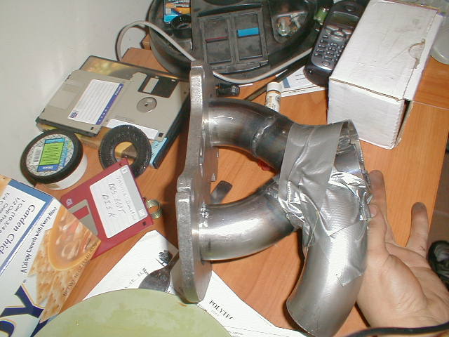
Well, I got the runners into the flange, but i'm stuck on the fact that they're a good bit off centr (there's a ~1/8" gap on the outside of each hole of the flange (towards the front / back of the engine). This will overlap with the exhaust ports, which I don't like, but It may be the only way to do it for the time being. I may end up splitting the runners near the flange and 'stretching' them out to get rid of the gap... we'll see!
Anyway, I was playing around with different locations for the wastegate runner, and came up with a couple of options...
It looks like it'll be possible to put a curved piece under the collector, heading back, but this puts the runner within about 1/2" of the motor mount, which can't be good for the rubber. It also makes routing the dump tube back into the downpipe much more 'interesting'.
So, my favorite spot at the moment is putting an elbow on the rear of the collector, right before the turbo flange (at a 90* angle), that points down and towards the rear corner of the engine (more or less). I attached a pic of the mockup (more duct tape... wahoo!). Is that placement going to work OK, or will it send me spiralling into turbo-rotary boost control hell?
Thanks,
Manolis
Anyway, I was playing around with different locations for the wastegate runner, and came up with a couple of options...
It looks like it'll be possible to put a curved piece under the collector, heading back, but this puts the runner within about 1/2" of the motor mount, which can't be good for the rubber. It also makes routing the dump tube back into the downpipe much more 'interesting'
.So, my favorite spot at the moment is putting an elbow on the rear of the collector, right before the turbo flange (at a 90* angle), that points down and towards the rear corner of the engine (more or less). I attached a pic of the mockup (more duct tape... wahoo!
). Is that placement going to work OK, or will it send me spiralling into turbo-rotary boost control hell? Thanks,
Manolis
Last edited by Manolis_D; Dec 3, 2002 at 01:55 AM.
Rotary Freak
Joined: Feb 2001
Posts: 2,524
Likes: 0
From: MN
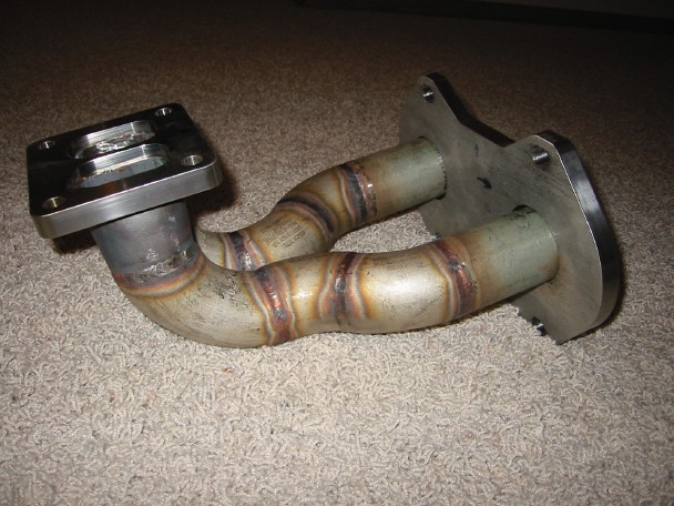
Is there anyway you can place the WG tube more center so it sees both exh ports better? What if you placed that 90deg fitting on top of the collector? How is your turbo going to sit on the manifold? Is the turbo flange going to be parallel with the engine flange or perpendicular to it? like mine is? As you can see I'm not too much farther than you and am still tring to make my WG runner decision like you
-Cam.
-Cam.
Thread Starter
Joined: Sep 2001
Posts: 932
Likes: 0
From: Altadena, CA
Hey setzep, nice looking manifold!
The turbo flange is more or less parallel with the engine flange (it's actually tilted a bit up / in at the front, to clear the smog pump and shock tower better, but it's just a few degrees). As far as the wastegate runner goes, if I put it on top of the collector then it comes within 1/2" of the intake manifold, and gives clearance problems with the downpipe. Putting it directly under the collector gives pretty good clearance everywhere except for the motor mount, which is within 3/8" or so. This wouldn't bug me too much, except that the motor mounts seem to go pretty quickly without the added 'benefit' of 1600* heat next to it. The way it is on the side won't be too bad I don't think, especially since the manifold is undivided.
I'll take a look at it tomorrow again and see if there's a better way to route it that I missed. I plan on building another manifold after this one anyhow (out of stainless hopefully, and with slightly better fit / finish), so if this ends up causing problems I can always revise it later
Yours is looking good! It looks like you have a bit more room to play with too, so hopefully you can get a slightly better location for the WG runner.
Stainless is sexy,
-Manolis
The turbo flange is more or less parallel with the engine flange (it's actually tilted a bit up / in at the front, to clear the smog pump and shock tower better, but it's just a few degrees). As far as the wastegate runner goes, if I put it on top of the collector then it comes within 1/2" of the intake manifold, and gives clearance problems with the downpipe. Putting it directly under the collector gives pretty good clearance everywhere except for the motor mount, which is within 3/8" or so. This wouldn't bug me too much, except that the motor mounts seem to go pretty quickly without the added 'benefit' of 1600* heat next to it
. The way it is on the side won't be too bad I don't think, especially since the manifold is undivided.I'll take a look at it tomorrow again and see if there's a better way to route it that I missed. I plan on building another manifold after this one anyhow (out of stainless hopefully, and with slightly better fit / finish), so if this ends up causing problems I can always revise it later
Yours is looking good! It looks like you have a bit more room to play with too, so hopefully you can get a slightly better location for the WG runner.
Stainless is sexy
,-Manolis
Rotary Freak
Joined: Feb 2001
Posts: 2,524
Likes: 0
From: MN
I don't know If I'd worry too much about the WG runner being 3/8 inch away from the motor mount all that much. Remeber the WG runners aren't going to be running near as hot as the main runners. Or maybe you could make a little shield to protect the mount?
-Cam
-Cam
Thread Starter
Joined: Sep 2001
Posts: 932
Likes: 0
From: Altadena, CA
Welllll.... I think i'll do that on manifold #2 (I, uh, just came back from grinding out a nice big hole in the manifold in the garage, for the wastegate runner). Once I get the downpipe set up, i'll have a better idea of how much space I have down there too. I remember now another issue with that was that it would have put the 'cold' side of the WG quite close to the DP (within an inch or so). Of course I could wrap the DP too, so I guess it wouldn't have been that big a deal!
This manifold is sortof to play around with a bit, and get some numbers from. I'm thinking of installing a pair of little pressure gauges on the manifold runners (via long tubes) and monitering the backpressure in each runner with and without the WG open. That should give a pretty good indication of any problems induced by having the WG runner there.
In a few weeks I'll be at this again, this time with Stainless. I just wanted to be sure everything would work before I dove into it with expensive materials!
-Manolis
(I, uh, just came back from grinding out a nice big hole in the manifold in the garage, for the wastegate runner). Once I get the downpipe set up, i'll have a better idea of how much space I have down there too. I remember now another issue with that was that it would have put the 'cold' side of the WG quite close to the DP (within an inch or so). Of course I could wrap the DP too, so I guess it wouldn't have been that big a deal!This manifold is sortof to play around with a bit, and get some numbers from. I'm thinking of installing a pair of little pressure gauges on the manifold runners (via long tubes
) and monitering the backpressure in each runner with and without the WG open. That should give a pretty good indication of any problems induced by having the WG runner there.In a few weeks I'll be at this again, this time with Stainless. I just wanted to be sure everything would work before I dove into it with expensive materials!
-Manolis
Rotary Freak
Joined: Feb 2001
Posts: 2,524
Likes: 0
From: MN
If you know someone that can machine the cost of stainless really isn't that bad (304 anyways). I payed $30 in material for the flanges, $15 for a 3' piece of pipe and $4.20 per 90 or 45 deg fitting you see there.
I sure wish I started my project when I was 18 like you! I might be actually driving my car by now!
-Cam
I sure wish I started my project when I was 18 like you! I might be actually driving my car by now!
-Cam
Thread Starter
Joined: Sep 2001
Posts: 932
Likes: 0
From: Altadena, CA
[quote]I sure wish I started my project when I was 18 like you! I might be actually driving my car by now!
[/i] LOL! heck, I started this thing last august (of 2001), and just got it running this august (it took 2 engines, a haltech, a drivetrain, etc ), and now i've taken it apart again. It's gotten to the point that taking it apart almost feels relieving... feels like it belongs that way (hehe).
I was seriously considering the stainless, but I wasn't sure that 304 was going to cut it. I was looking mainly at www.burnsstainless.com, which has some cool stuff. The thing is that they only sell in a max thickness of 16 gauge (.065"), so I wasn't sure the 304 would take the heat, and the 321 costs as much as <get ready...> titanium! Total cost for all of this has been like 45 bucks (2" diameter, 3" CLR U-bends from Racing Beat, and their 13B flange).
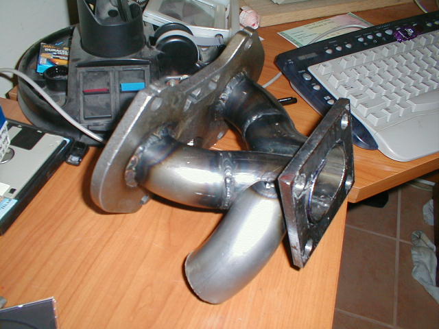
I got the WG runner tacked on today, and made the Turbo Flange. It's almost there! Here's a pic of the thing:
[/i] LOL!
heck, I started this thing last august (of 2001), and just got it running this august (it took 2 engines, a haltech, a drivetrain, etc ), and now i've taken it apart again. It's gotten to the point that taking it apart almost feels relieving... feels like it belongs that way (hehe).I was seriously considering the stainless, but I wasn't sure that 304 was going to cut it. I was looking mainly at www.burnsstainless.com, which has some cool stuff. The thing is that they only sell in a max thickness of 16 gauge (.065"), so I wasn't sure the 304 would take the heat, and the 321 costs as much as <get ready...
> titanium! Total cost for all of this has been like 45 bucks (2" diameter, 3" CLR U-bends from Racing Beat, and their 13B flange).I got the WG runner tacked on today, and made the Turbo Flange. It's almost there!
Here's a pic of the thing:Last edited by Manolis_D; Dec 5, 2002 at 08:25 PM.
Rotary Enthusiast
Joined: Nov 2002
Posts: 1,021
Likes: 2
From: -
Looking pretty good so far. I think the WG runner being on the side will work fine. It might be better on the top or bottom, but unless you are running very high boost levels, your design should work nicely.
Thread Starter
Joined: Sep 2001
Posts: 932
Likes: 0
From: Altadena, CA
*phew* thanks. I was worrying about that a bit
I still think that it'd be pretty cool to plumb in two pressure sensors, if for nothing else then to see the backpressure:boost pressure ratio. That would be interesting I think!
Now to finish welding this thing and make the intake piping, etc!
I still think that it'd be pretty cool to plumb in two pressure sensors, if for nothing else then to see the backpressure:boost pressure ratio. That would be interesting I think!
Now to finish welding this thing and make the intake piping, etc!
Rotary Freak
Joined: Feb 2001
Posts: 2,524
Likes: 0
From: MN
Looks good! Your passing me up. Now that I look at it again I woulden't worry about the WG placement, I bet it will work good. All the wastegate does is bleed off pressure anyways, doesn't really have to have a nice even flow like the main runners do to the turbo.
I do have one concern though. With your turbo being mounted that low on the engine how are you going to run your turbo drain line? Looks to me that it's going to almost have no down slope to the engine.
-Cam
I do have one concern though. With your turbo being mounted that low on the engine how are you going to run your turbo drain line? Looks to me that it's going to almost have no down slope to the engine.
-Cam