
Exhaust Manifold Comparisons (need input and suggestions)

Thread Starter
BDC Motorsports
Joined: Jun 2002
Posts: 3,667
Likes: 6
From: Grand Prairie, TX
Exhaust Manifold Comparisons (need input and suggestions)
Hey folks,
As some of you guys know from reading this forum, 87GTR and I myself have been testing out a BorgWarner S300 turbo (same unit Max is setting up in his car) over the past few days. We just got it running yesterday afternoon. The turbine housing is the 1.15 A/R derivative of the three options they've got so it's the smallest for that particular trim. However, I'm unfamiliar with the trim as well as options relating to building hybrids when it comes to BW, 3K turbos. We've got the turbo mounted on an HKS exhaust manifold (undivided), using a Racing Beat spacer, as well as an undivided T4 flange spacer inbetween it and the turbo. The inlet on the turbocharger is T4 divided.
The problem we're having is the lack of boost response. The engine is a street-ported, half-bridgeported (cuts on the front and rear plates) 13B 4-port motor. The previous turbo being used was a TO4E 60trim that, with the engine the way it is, was real peaky in the mid-range and would fall off to about 12psi of boost by the high-end. It previously made almost 380rwhp and 330ft/lbs of torque at 12psi. The turbo was changed to meet the power goals as well as for the purpose of having one that can meet the demand of the engine's "lungs". The new turbo, with vacuum and exhaust leaks hopefully eliminated, is taking forever to spool. It will build up to about 0.3 bar of boost by the end of the first gear and will hit about 10psi past 7kRPM's in 2nd. Unsure of 3rd but I suspect it'd hit full boost.
The question I've got deals with the usage of different exhaust manifolds as a way of reducing turbulence and retaining exhaust gas velocity to help accelerate a/the turbocharger earlier in the power band. Although I'm unsure of the real-world effects, having an undivided manifold feeding into a divide turbine housing will be turbulent and will cause a greater spool-up time. What'd I'd like to get from some of you guys that have tried different manifolds, as well as divided vs. undivided, are the results of both. Anyone else here used any superior exhaust manifold (over HKS) that you'd recommend?
Thanks,
B

Banned. I got OWNED!!!
Joined: Mar 2001
Posts: 2,306
Likes: 1
From: lebanon
The biggest issue is the manifold!!!
I have seen similar problems when runing the same set up on similar cars to yours, that is one pretty f*cking big turbo you have there, and running in "non pulsed" is the root cause of all your problems.
basically each pulse as it reachs the turbine section is reduced in it's effectivness as it looses energy over the massive area (of two runners, instead of one) and combine this fact with that manifold not being of a tunned length (very critical component) and you can basically negate the benifits ofered by exhaust pulsing to all but eliminate "lag".
You are not harnessing the inherent power of the rotary to drive that turbine section, you should be able to pull what ever boost pressure you set as you maximum by second gear with ease.
There will be a night and day difference if you put a fully divided tuned leangth header on that baby, then you will harness the full power making potential of that turbo! There are people here who use 1.22a/r exhaust housings on T51 turbos (larger than a Q trim wheel) running just side ports and don't have the problems you are experiencing)
Make a good header, and see what it's like. You will love it!
Thread Starter
BDC Motorsports
Joined: Jun 2002
Posts: 3,667
Likes: 6
From: Grand Prairie, TX
Hey Rice, when you're referring to tuned length headers, what exact length are you talking about? What I've heard from others is that the manifold runners need to be atleast 3" long prior to collecting. This certainly isn't the case in the HKS div manifold. Got any ideas or suggestions for us? We'll probably have a manifold made sometime soon.
Thanks much,
B
Thanks much,
B
Banned. I got OWNED!!!
Joined: Mar 2001
Posts: 2,306
Likes: 1
From: lebanon
My last manifold was exactly 13" from the base plate to the turbine plate, measured through the centerline of the header pipe.
My current manifold is around 16", it is of great importance that both pipes be the same length to within %95 the closer the better, especially on a bridge motor or a normal street port with big exhaust ports, having the pipes merge too early has a double bad effect that the "tuned range" is wrong (happens far to high & hence does not help the scavenging of the engine) but the biggest problem is the exhaust cycle of one rotor has an effect on the other rotor with shorter manifold pipes (similar to negative performance of a log manifold v's a header).
I use the same theory on the WG tubes keep them seperate untill the base of the WG this will keep the maximum energy of the pulse and help with your spool and also have a positive effect on the "gas pressure exchange between front and rear rotor" If you realy can do it keep the point of interference of the wastegate tubes the same length as measured from the block to the point in which they collect, this is the ideal and will mean same pulse tuning for this section of the manifold as well. It's hard but can be done! I would show you picks of my lattest manifold but as yet have not developed the photo's
There are big differences in spool and turbo responce when running a tuned manifold, night & day compared to what you have now Do not make it shorter than 9" or it will be tuned for to high a range and your spool will suffer the shorter the manifold you make. I used 2"ID for the ones I make, and don't forget to keep it divided and keep the WG pipes divied as well untill just before the WG.
Works for me

Full Member
Joined: Mar 2003
Posts: 129
Likes: 0
From: New Orleans
Thanks for the input Rice Racing, BDC and I will be making a manifold soon and your pictures will help a lot. You think 16 inches is Ideal? or can we be a bit shorter if space and location becomes and issue? Also do you have any pictures of your old manifold. Interesting stuff about wastegate pipes, i never paid that much attention to them before. Thanks for the idea and input.
Hassan
Hassan
Trending Topics
Banned. I got OWNED!!!
Joined: Mar 2001
Posts: 2,306
Likes: 1
From: lebanon
Originally posted by turbo-rotary
Thanks for the input Rice Racing, BDC and I will be making a manifold soon and your pictures will help a lot. You think 16 inches is Ideal? or can we be a bit shorter if space and location becomes and issue? Also do you have any pictures of your old manifold. Interesting stuff about wastegate pipes, i never paid that much attention to them before. Thanks for the idea and input.
Hassan
The longer you can make it the better in my book, as there is less time for the negative effects of one rotors cycle to impact on the other rotor. Try to be logical though, there is no point making a serpentine style header with lots of bends just to get the length you want, it will reduce the flow through the header and hence the engine, You will find that if the turbo is lifted higher and further forward of its current position and with a few minor bends it will work out to around 16" in length which will work real nice, its a hard job getting the pipes equal lengths but the effort is worth it for sure! And yes dont undo your hard work by plumbing in the WG the wrong way and hence letting the gas transfer well before it would if it went all the way to the turbine housing merge point.
I will develope the film on Monday once I scan it I will send you some pics of what I did for my new style manifold.
Banned. I got OWNED!!!
Joined: Mar 2001
Posts: 2,306
Likes: 1
From: lebanon
It will have two distinct tuned points due to the shorter path between front and rear rotors via the WG runners, about half the lenght of the path taken to the merge point in the exhaust housing. It is not ideal but what in life is????
As the pipes for the WG are quite short there will be a fair degree of negative pressure affecting the other rotor due to this shorter pathway through the WG tubes, On my manifold I plumbed my WG to the TOP (in the engine bay) so I could get the length I wanted to negate this difference in merge point as compared to when the gases collect in the turbine housing.
I did a fair bit of thinking about this issue and this was the only way I could resolve it, bare buying another WG and running one of each runner and then making sure each had the same length of pipe (near impossible in an RX7 engine bay) so i decided on the later solution, I realy need to post some pics........will do very soon!
But suffice to say the WG pipe on the rear rotor comes of the rear runner about 5" along the pipe and the front comes off about 10" along the pipe and each pipe is 15" and 10" long respectivley so they have the same distance from exhaust port to collection point @ the WG, each main runner is about 16" and they collect into the divided housing about 5" up the housing. So the two collection points are similar so that is the ideal situation tuning wise in my mind as they are almost the same length.
It is very interesting when I do an acoustic test on the manifold with the turbo and WG bolted up to it, if I bang the palm of my hand over the header runner on either the front of rear it makes exactly the same resonant sound from front to rear which means it must be pretty close See how it goes in practise, still have allot of stuff to fabricate
As the pipes for the WG are quite short there will be a fair degree of negative pressure affecting the other rotor due to this shorter pathway through the WG tubes, On my manifold I plumbed my WG to the TOP (in the engine bay) so I could get the length I wanted to negate this difference in merge point as compared to when the gases collect in the turbine housing.
I did a fair bit of thinking about this issue and this was the only way I could resolve it, bare buying another WG and running one of each runner and then making sure each had the same length of pipe (near impossible in an RX7 engine bay) so i decided on the later solution, I realy need to post some pics........will do very soon!
But suffice to say the WG pipe on the rear rotor comes of the rear runner about 5" along the pipe and the front comes off about 10" along the pipe and each pipe is 15" and 10" long respectivley so they have the same distance from exhaust port to collection point @ the WG, each main runner is about 16" and they collect into the divided housing about 5" up the housing. So the two collection points are similar so that is the ideal situation tuning wise in my mind as they are almost the same length.
It is very interesting when I do an acoustic test on the manifold with the turbo and WG bolted up to it, if I bang the palm of my hand over the header runner on either the front of rear it makes exactly the same resonant sound from front to rear which means it must be pretty close
See how it goes in practise, still have allot of stuff to fabricate
Thread Starter
BDC Motorsports
Joined: Jun 2002
Posts: 3,667
Likes: 6
From: Grand Prairie, TX
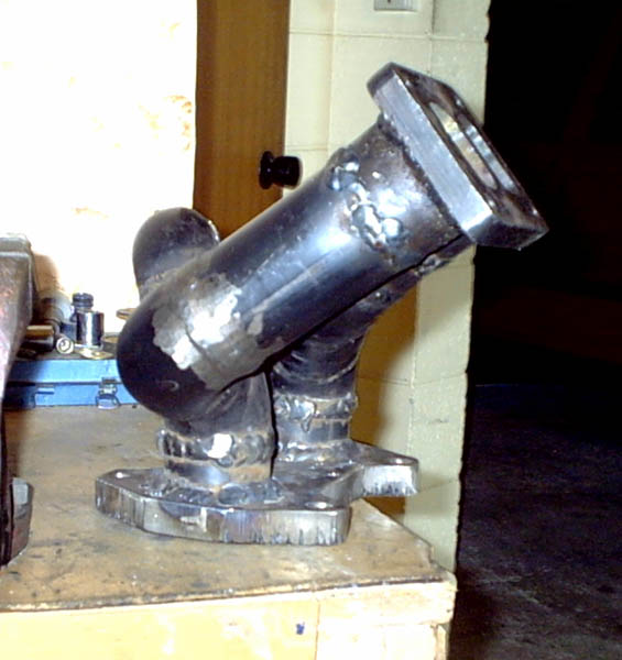
Thanks, Rice. You also have to figure in the length of the runners on the turbine housing itself I believe. Let me see if I have a photo here showing them; they're quite long. I was surprised to see how long the casting was on this housing. Perhaps they can be thought of as "runner length".
Here's two:


Notice the length of these runners. Unlike some of the more common TO4's out there, these seem to run for several inches...
Also, I was going to ask about the use of a pair of 35mm WG's (either on their own, separate runner) instead of collecting two runners to one large 46mm WG... what do you think? Open-air vented, of course.
B
Here's two:
Notice the length of these runners. Unlike some of the more common TO4's out there, these seem to run for several inches...
Also, I was going to ask about the use of a pair of 35mm WG's (either on their own, separate runner) instead of collecting two runners to one large 46mm WG... what do you think? Open-air vented, of course.
B
Last edited by BDC; May 17, 2003 at 12:38 PM.
Rotary Freak
Joined: Feb 2001
Posts: 2,524
Likes: 0
From: MN
Originally posted by RICE RACING
It will have two distinct tuned points due to the shorter path between front and rear rotors via the WG runners, about half the lenght of the path taken to the merge point in the exhaust housing. It is not ideal but what in life is????
It will have two distinct tuned points due to the shorter path between front and rear rotors via the WG runners, about half the lenght of the path taken to the merge point in the exhaust housing. It is not ideal but what in life is????
As the pipes for the WG are quite short there will be a fair degree of negative pressure affecting the other rotor due to this shorter pathway through the WG tubes
But this isn't the worst WG runner setup you have seen though is it?sorry for highjacking the thread

This thread is great! I've been looking for something like this forever. Great info Rice!
Along these lines, has anyone seen somewhere that sells divided SS T4 flanges and or SS turbo engine flanges? I can make my own, but I figure it'll be cheaper if someone already makes them.
Along these lines, has anyone seen somewhere that sells divided SS T4 flanges and or SS turbo engine flanges? I can make my own, but I figure it'll be cheaper if someone already makes them.
inteligent extratarestril
Joined: Mar 2001
Posts: 1,313
Likes: 0
From: The Sunny B.O.P, New Zealand
Peter bro, check out this handy work
after lots of hours of design, head scratching and trail fitments this is what i managed to come up with.
main runners are 50mm ID 5mm wall thickness
wastegate runners are 40mm ID 5mm wall thickness
front runner is 355mm from engine flange (engine side) to turbo flange (turbo side)
after lots of hours of design, head scratching and trail fitments this is what i managed to come up with.
main runners are 50mm ID 5mm wall thickness
wastegate runners are 40mm ID 5mm wall thickness
front runner is 355mm from engine flange (engine side) to turbo flange (turbo side)
Last edited by HWO; May 17, 2003 at 08:32 PM.
inteligent extratarestril
Joined: Mar 2001
Posts: 1,313
Likes: 0
From: The Sunny B.O.P, New Zealand
you guys with left hand drive cars have nothing to worry about when it comes to doing manifolds compared to us guys with steering shafts, steering boxes etc in the road
Last edited by HWO; May 17, 2003 at 10:12 PM.
Rotary Freak
Joined: Jan 2002
Posts: 1,643
Likes: 0
From: l.a.
Originally posted by setzep
When you say two distinct tuned points what do you mean exactly? Will I be able to feel more "pull" or hp at two different RPM's?
I tried to think of just about every possibility on how to run the WG runners. In the end I used this because it was what fitted in the space I had and it allowed me to mount the WG upside down so the diaphragm woulden't get as heat soaked. I guess I never thought about moving the WG towards the front of the car.... hmm... maybe next manifold I make But this isn't the worst WG runner setup you have seen though is it?
sorry for highjacking the thread
When you say two distinct tuned points what do you mean exactly? Will I be able to feel more "pull" or hp at two different RPM's?
I tried to think of just about every possibility on how to run the WG runners. In the end I used this because it was what fitted in the space I had and it allowed me to mount the WG upside down so the diaphragm woulden't get as heat soaked. I guess I never thought about moving the WG towards the front of the car.... hmm... maybe next manifold I make
But this isn't the worst WG runner setup you have seen though is it?sorry for highjacking the thread
Rotary Freak
Joined: Feb 2001
Posts: 2,524
Likes: 0
From: MN
Originally posted by fdracer
he means there are 2 points for pressure wave tuning. usually you get reversion at a merge collector and depending on the length and diameter or your primaries you can get a negative node to reach the exhaust port at a specific rpm range. in your case you also get reversion at the wg that is a certain distance down the primaries from the exhaust port. depending on the exact distance away from the exhaust port that the wg is place, this second point of reversion could help or hurt you. at best it could broaden your torque curve and not hurt spool too much, and at worst it could increase lag and lower your torque.
he means there are 2 points for pressure wave tuning. usually you get reversion at a merge collector and depending on the length and diameter or your primaries you can get a negative node to reach the exhaust port at a specific rpm range. in your case you also get reversion at the wg that is a certain distance down the primaries from the exhaust port. depending on the exact distance away from the exhaust port that the wg is place, this second point of reversion could help or hurt you. at best it could broaden your torque curve and not hurt spool too much, and at worst it could increase lag and lower your torque.
inteligent extratarestril
Joined: Mar 2001
Posts: 1,313
Likes: 0
From: The Sunny B.O.P, New Zealand
fire the welder? which one in particular, a mate welded the main runners, an engineer welded the engine and turbo flanges on and seamed the runners together at the turbo flange end, and i welded everything associcated with the wastegate runners. Having a welder which is consistant is a BIG help, the wire speed on the MIG i used plays up from time to time, also, having done one manifold, if i were to do it again i would do the wastegate runners etc onto the main runners, then fizz the whole lot together onto the flanges
Banned. I got OWNED!!!
Joined: Mar 2001
Posts: 2,306
Likes: 1
From: lebanon
BDC, the HWO and SETZEP headers are good examples of what I mean about a tunned length header, this is the biggest key factor to get rid of that "responce problem".
HWO WG runners are showing what I was talking about.
In regards to the two different reversion points, when you do this the maximum effect of this principle is reduced when you have two elements that are tuned for different ranges (collection point from WG to both front and rear rotor exhaust port). If you can get them a the same or near enough then the effect will be greater in that range.
BDC stick to the Tial 46mm (I use one on my new T51 set up) it is more than enough for any well set up 13B and so long as you plumb it up good, following the priciples talked about above you will love it. I will need someone to host my pics when I get them scaned so if you can do this send me a PM and I will put my little effort up here and see if that gives you some ideas/help
Also BDC looking at your exhaust housing the distances assosiated stick with the specs I gave you in the first replys (13" to 16" long from engine flange to tubine flange) it will work great!!! And make em the same length
Rotary Freak
Joined: Feb 2001
Posts: 2,524
Likes: 0
From: MN
Originally posted by HWO
fire the welder? which one in particular, a mate welded the main runners, an engineer welded the engine and turbo flanges on and seamed the runners together at the turbo flange end, and i welded everything associcated with the wastegate runners. Having a welder which is consistant is a BIG help, the wire speed on the MIG i used plays up from time to time, also, having done one manifold, if i were to do it again i would do the wastegate runners etc onto the main runners, then fizz the whole lot together onto the flanges
fire the welder? which one in particular, a mate welded the main runners, an engineer welded the engine and turbo flanges on and seamed the runners together at the turbo flange end, and i welded everything associcated with the wastegate runners. Having a welder which is consistant is a BIG help, the wire speed on the MIG i used plays up from time to time, also, having done one manifold, if i were to do it again i would do the wastegate runners etc onto the main runners, then fizz the whole lot together onto the flanges