
EFR 8374 Impressions

Thread Starter
"Elusive, not deceptive!�
Joined: May 2007
Posts: 930
Likes: 13
From: Slidell, LA
EFR 8374 Impressions
After 15 years of high EGTs my old cast iron HKS manifold started to crack. I decided to go to a new set up.
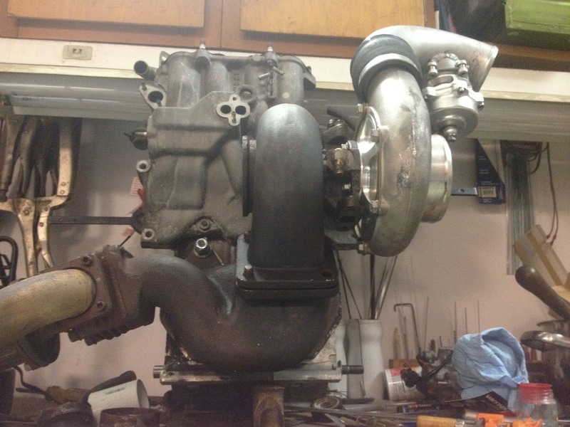
This old system was a well balanced.... but it had started with a TO4S and now with a TO4Z it was more turbo than I needed.... and both took up a lot of space.
This is what the old set-up looked like with a TO4Z, 50MM wastegate and 40MM BOV.
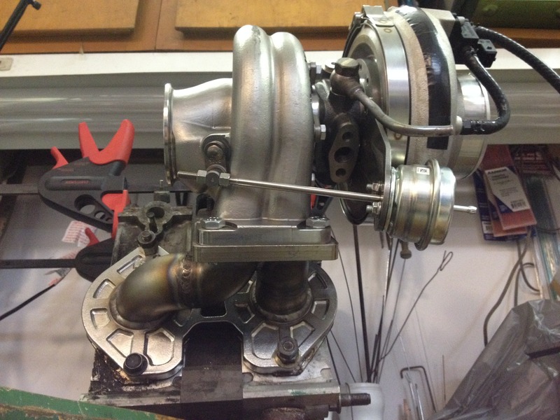
This next picture is all the same pieces (wastegate/turbo/BOV) by using the EFR set-up.
Most things that I modify I try to follow the thought process of "How would Mazda do it?".... lightweight, compact, and dependable.
I wanted to keep the turbo low like my cast HKS so I wouldn't have to change my set-up to much.
Turblown's shorty manifold fits this requirement well but since I really like making things myself I thought I would give a try.
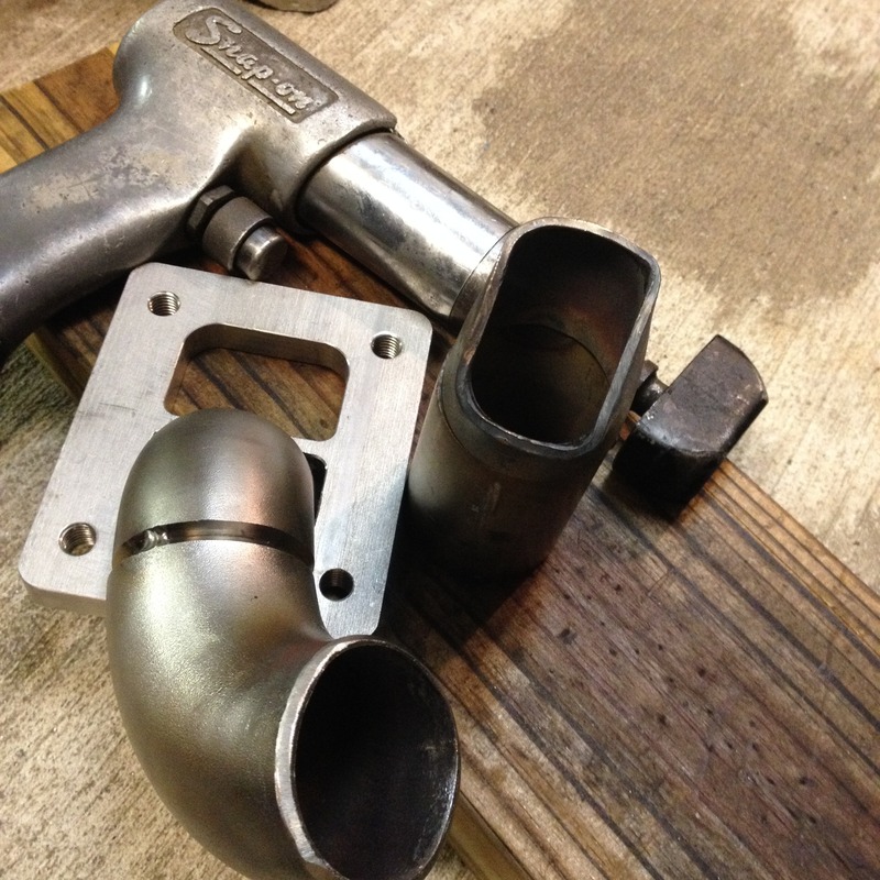
We used 1 1/2"schedule 10 weld els and a Racing Beat flange. And made a special tool to shape the transition to the t4 flange.
(I work with Jonathan at Gorilla Race Engineering about once a week so any special tool can be shared.)
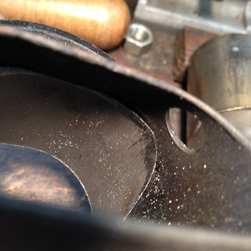
But I was not happy with possible flow interruption coming from the exhaust sleeve.
It starts at 1.810 sq in at the port and tapers to 2.985 sq in at the housing flange. But the tubing size is 1.650" so it is only 2.137 sq in.
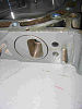
I decided to make a transitional sleeve of sch 10 to fit into the exh sleeve to smooth flow so that it never opened full to the 1.950 size.
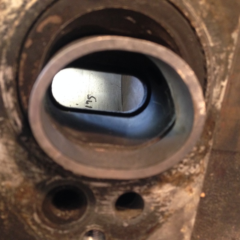
This is how it looks from the port outward.
I do not recommend this method.
The next manifold will be 2"321 schedule 40 which is 2.067" just slightly larger than the 1.950" housing flange.
My impression of the EFR 8374 is all good. It uses cells on our maps that were never truly tunable before.
The other thing I noticed was my water/meth indicator light (@10 psi initiation) would flash on much earlier.... all good.
A very nice turbo, thank you Elliot at Turblown and Jonathan at Gorilla for your help.
Barry Bordes
This old system was a well balanced.... but it had started with a TO4S and now with a TO4Z it was more turbo than I needed.... and both took up a lot of space.
This is what the old set-up looked like with a TO4Z, 50MM wastegate and 40MM BOV.

This next picture is all the same pieces (wastegate/turbo/BOV) by using the EFR set-up.

Most things that I modify I try to follow the thought process of "How would Mazda do it?".... lightweight, compact, and dependable.
I wanted to keep the turbo low like my cast HKS so I wouldn't have to change my set-up to much.
Turblown's shorty manifold fits this requirement well but since I really like making things myself I thought I would give a try.

We used 1 1/2"schedule 10 weld els and a Racing Beat flange. And made a special tool to shape the transition to the t4 flange.
(I work with Jonathan at Gorilla Race Engineering about once a week so any special tool can be shared.)
But I was not happy with possible flow interruption coming from the exhaust sleeve.
It starts at 1.810 sq in at the port and tapers to 2.985 sq in at the housing flange. But the tubing size is 1.650" so it is only 2.137 sq in.
I decided to make a transitional sleeve of sch 10 to fit into the exh sleeve to smooth flow so that it never opened full to the 1.950 size.

This is how it looks from the port outward.

I do not recommend this method.
The next manifold will be 2"321 schedule 40 which is 2.067" just slightly larger than the 1.950" housing flange.
My impression of the EFR 8374 is all good. It uses cells on our maps that were never truly tunable before.
The other thing I noticed was my water/meth indicator light (@10 psi initiation) would flash on much earlier.... all good.
A very nice turbo, thank you Elliot at Turblown and Jonathan at Gorilla for your help.
Barry Bordes


No problem Barry! You might be intersted in our new cast iwg manifolds. The ID is the same as the exhaust sleeve and tapers down to the size of the T4 divided flange. It would be impossible to build this by welding. It is also being cast with twin egt/embp bungs and strengthened in other areas.

Thread Starter
"Elusive, not deceptive!�
Joined: May 2007
Posts: 930
Likes: 13
From: Slidell, LA
No problem Barry! You might be intersted in our new cast iwg manifolds. The ID is the same as the exhaust sleeve and tapers down to the size of the T4 divided flange. It would be impossible to build this by welding. It is also being cast with twin egt/embp bungs and strengthened in other areas.
Do you have any pictures of the new manifold to tease us with?


 . Always a pleasure!
No problem Barry! You might be intersted in our new cast iwg manifolds. The ID is the same as the exhaust sleeve and tapers down to the size of the T4 divided flange. It would be impossible to build this by welding. It is also being cast with twin egt/embp bungs and strengthened in other areas.
Trending Topics

Thread Starter
"Elusive, not deceptive!�
Joined: May 2007
Posts: 930
Likes: 13
From: Slidell, LA

Thread Starter
"Elusive, not deceptive!�
Joined: May 2007
Posts: 930
Likes: 13
From: Slidell, LA
Hey Steven,
This thread is really because you were asking about building manifolds.
I thought others might also be interested different building techniques.
But you want/need a long tube manifold for your RX8 REW.... a special case.
You are going to love your new 8374.
Barry
This thread is really because you were asking about building manifolds.
I thought others might also be interested different building techniques.
But you want/need a long tube manifold for your RX8 REW.... a special case.
You are going to love your new 8374.
Barry

Manifold failure from heat: Heat/energy/exhaust gases can really cause a lot of damage, especially when in its transitional space between the port and the turbine housing, ie turbo manifold. When the exhaust flow is not evacuated/removed from the engine and sent to the turbine in a fluid path, the areas of turbulence are the points that can and will fail. The "seamless" fit and placement of the custom pre-manifold sleeves are such that there is no high pressure edges for the exhaust gas to get "stuck" on. Since the flow is "smooth", the sleeve is merely acting as a "bridge" for the gases to retain their velocity from port to manifold. All of that said, it is still pending on the physical materials chosen be up to the task at hand.
-J
Could you expand/provide more info on the special tool to shape the transition to the t4 flange? and how it was used?
Last edited by GoodfellaFD3S; Jun 20, 2015 at 06:01 AM.
Thread Starter
"Elusive, not deceptive!�
Joined: May 2007
Posts: 930
Likes: 13
From: Slidell, LA
So a mandrel is made to shape the pipe exactly to the flange.
Then heat the pipe with an acetylene torch to red and drive the mandrel in using a rivet gun
(at the proper clock-angle transitioning from the port).
Another view of the shaped end and the oval transition piece that enhances/sustains velocity.
and "i have no experience in fabrication or materials, but question/curiosity of
the transitional piece collapsing under the rotary's exhaust pressure and heat. Any insight?"
You are correct in thinking that heat could distort and cause a possible failure.
The pipe is almost 1/8" thick and the main exhaust blast hits the floor of the port sleeve.
The sharp fitted top section is next to the air pump bleed holes.
Have you ever seen those distorted from the heat?
But it could happen... and as one of our forum members says... a test is worth more than a theory ( I paraphrase).
This manifold experiment was an attempt to have the highest velocity and flow to give early spool.
The next will compare a 2" set-up to it.

Last edited by Barry Bordes; Jun 19, 2015 at 02:19 PM.
If you look at the T4 flange... they vary somewhat but this one has a slight ""D shape.
So a mandrel is made to shape the pipe exactly to the flange.
Then heat the pipe with an acetylene torch to red and drive the mandrel in using a rivet gun
(at the proper clock-angle transitioning from the port).
Another view of the shaped end and the oval transition piece that enhances/sustains velocity.
and "i have no experience in fabrication or materials, but question/curiosity of
the transitional piece collapsing under the rotary's exhaust pressure and heat. Any insight?"
You are correct in thinking that heat could distort and cause a possible failure.
The pipe is almost 1/8" thick and the main exhaust blast hits the floor of the port sleeve.
The sharp fitted top section is next to the air pump bleed holes.
Have you ever seen those distorted from the heat?
But it could happen... and as one of our forum members says... a test is worth more than a theory ( I paraphrase).
This manifold experiment was an attempt to have the highest velocity and flow to give early spool.
The next will compare a 2" set-up to it.
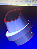
Maybe I can contribute a little here also. My brother is a machinist and programmer. I commissioned him to help make me a pair of new exhaust sleeves that would essentially do the same thing Barry is accomplishing with the "bridge" pieces.
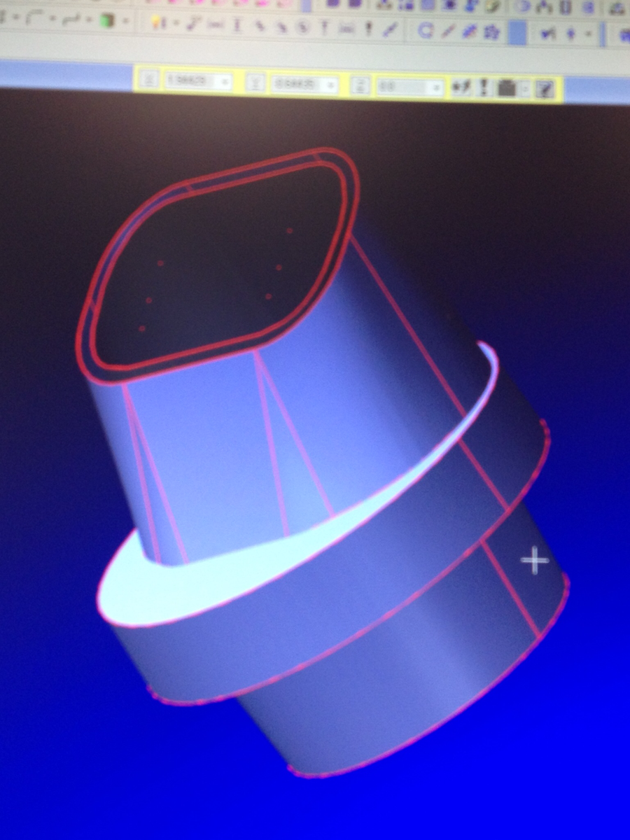
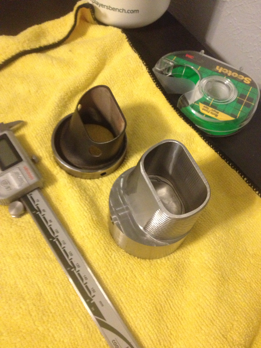
I wanted the entrance of the sleeve to be closer to the housing port with very little gap. And the exit side of the sleeve would be designed to be longer and to protrude into the manifold to get closer to the runner and have same I.D. as manifold.
In the middle of the project he started full time M.E. classes a lot heavier and works full time so the project was set aside for now but I hope to complete it later.
The sleeves are designed to be able to be swapped with the engine together using custom made "set screws" and the factory sleeves were modified to use them also.
I know it's useless really with no results but may be interesting nonetheless so enjoy the pics.

Others have done this before.
It will spool the turbo faster.
EGTs go through the roof at the turbine wheel as the exhaust gas combustion/expansion now happens at the turbine wheel instead of the port to runner transition. It melts turbos down.
It will spool the turbo faster.
EGTs go through the roof at the turbine wheel as the exhaust gas combustion/expansion now happens at the turbine wheel instead of the port to runner transition. It melts turbos down.
During my research I did find someone else who tried a similar approach and if remember correctly they did actually melt a turbine wheel, but they were trying to keep the sleeve and manifold the same area or I.D. as the housing port.
My goal was only to smooth the transition from port to manifold runner, of course EGT monitoring would be imperative to guard against catastrophic failure during the initial testing phase.
My goal was only to smooth the transition from port to manifold runner, of course EGT monitoring would be imperative to guard against catastrophic failure during the initial testing phase.

Last edited by Andre The Giant; Jun 20, 2015 at 09:00 AM.
Thread Starter
"Elusive, not deceptive!�
Joined: May 2007
Posts: 930
Likes: 13
From: Slidell, LA
There is still an some expansion of gases.
It starts at 1.810 sq in at the port and tapers open to 2.137 sq in instead of 2.985 sq in at the housing flange.
But what is gained by allowing it to open larger (to 2.985) than immediately (1/2" downstream) forcing it into the 1.650" tube?
Andy, Tell your brother nice work on the drawings.
Elliot this 347 SS cast manifold sound great.
Blue- My EGTs do seem to be higher... actually they switched from the front rotor higher to rear...
But this may be an inaccurate observation/comparison because I installed new/different brand EGT sensors.
(Sensor Connection Type K EGT-CP vs PLX sourced sensors)
Last edited by Barry Bordes; Jun 20, 2015 at 11:50 AM.

t-von, I thought that was a good idea when I read about it in your build thread. If I made a change to my design, it would be to weld the sleeve to the manifold flange to make it similar to your design.