
Custom UIM Pictures?

Thread Starter
Joined: Jul 2002
Posts: 1,723
Likes: 1
From: Indianapolis
Custom UIM Pictures?
Does anyone have any pictures of custom UIMs that they have either built themselves or had others build? I know there are a few floating around out there.
Also, any numbers on gain achieved with the custom UIM would be nice as well.
Thanks!
Also, any numbers on gain achieved with the custom UIM would be nice as well.
Thanks!
Made this one about seven/eight years ago. (I say that because I can't believe it's been that long) I could email ya bigger pics if needed. I also got a ton of other more drag oriented pics as well.
~S~
~S~

Rotary Enthusiast
Joined: Oct 2007
Posts: 799
Likes: 3
From: Plymouth, MN
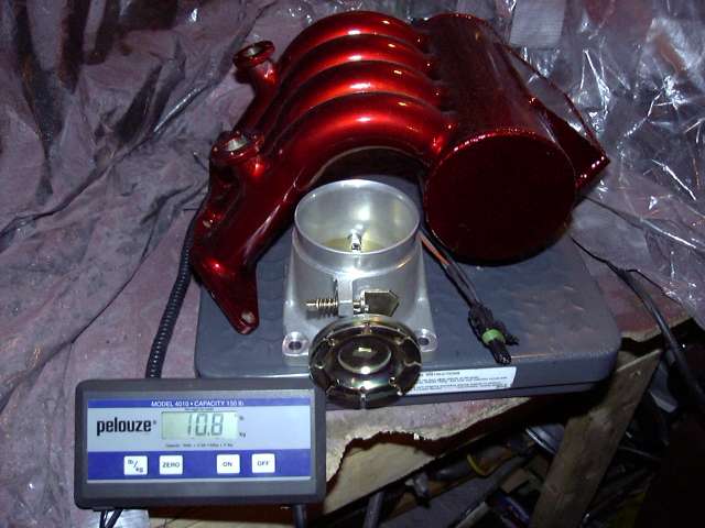
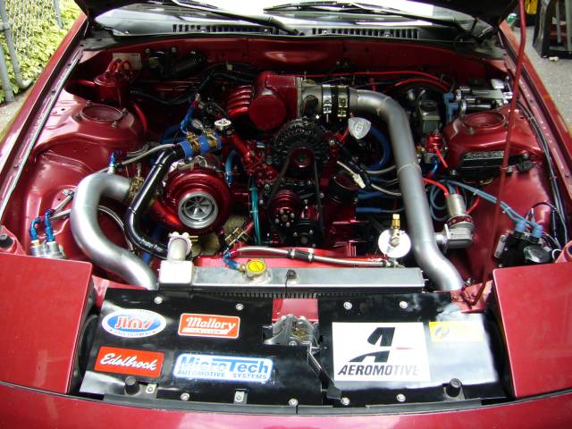
I built this one for my Renesis. It made a huge difference and its still a rotary 13B with a large turbo and 500whp+ so the design should apply somewhat.
I built it using a 5" extrusion for the plenum that has a flat on one side and 3.5 elbow from the throttle to the plenum, the pics don't do justice to the size of the manifold. The runners are 1.5" on the two on the outside for the aux 5th&6th ports and 2" for the middle that were "ovaled" so both primary and secondary ports can flow through it for the renesis to work normally.
Pics:
Some components:

Mocking primary runners up (they feed both the primaries and the secondary ports):

Mocking the Aux port runners 1.5":

Finished 1:

Finished 2:

Finished 3:

Complete final setup:

Let me know if you have any questions.
Chris
I built it using a 5" extrusion for the plenum that has a flat on one side and 3.5 elbow from the throttle to the plenum, the pics don't do justice to the size of the manifold. The runners are 1.5" on the two on the outside for the aux 5th&6th ports and 2" for the middle that were "ovaled" so both primary and secondary ports can flow through it for the renesis to work normally.
Pics:
Some components:
Mocking primary runners up (they feed both the primaries and the secondary ports):
Mocking the Aux port runners 1.5":
Finished 1:
Finished 2:
Finished 3:
Complete final setup:
Let me know if you have any questions.
Chris
Born to lose..Live to win
Joined: Mar 2010
Posts: 27
Likes: 0
From: Jersey Shore
Ive been tossing around the idea of putting a one off intake manifold together myself, I think one of the best looking units Ive seen is the one off Chato Ibarras drag FD, I attached a pic....I would change a few things though, mainly the plenum, I would want a more rounded unit, I found a company that sells universal plenums in the style I am thinking of, I attached a pic of the plenum below, and heres the website.... http://nozzs.com/index.phpmain_page=...roducts_id=132
For $200.00 it should do the job. Ofcourse you gotta go with a new throttlebody and fab up some runners but all that stuff should be easy to source. I would go with a Wilsons 90mm throttle body and tappered runners, and to finish the unit, clamp that sucker down with Willians clamps to make sure that sucker aint going nowhere. Oh ya, you should also relocate the altenator so your plenum can be moved more central in the engine bay so your runners arent a mile long.....should fit under the plenum piping if you ditch the power steering, or go with a pump relocation of some sort. Anybody wanna chime in on these ideas?
For $200.00 it should do the job. Ofcourse you gotta go with a new throttlebody and fab up some runners but all that stuff should be easy to source. I would go with a Wilsons 90mm throttle body and tappered runners, and to finish the unit, clamp that sucker down with Willians clamps to make sure that sucker aint going nowhere. Oh ya, you should also relocate the altenator so your plenum can be moved more central in the engine bay so your runners arent a mile long.....should fit under the plenum piping if you ditch the power steering, or go with a pump relocation of some sort. Anybody wanna chime in on these ideas?
Thread Starter
Joined: Jul 2002
Posts: 1,723
Likes: 1
From: Indianapolis
My thoughts were to use an xcessive LIM just for simplicity's sake and just to replace the UIM since i have this nice 90mm throttle body ready to bolt up.
Born to lose..Live to win
Joined: Mar 2010
Posts: 27
Likes: 0
From: Jersey Shore
Just chop up a stock upper intake manifold and mate it to a new plenum...this way it will bolt right up to the ground zero / xcessive lower intake manifold..I believe that is what the PFS intake manifold that Ray made for Ernie T consist of. The plenum I attached will probably still require you to move the alternator, but you can just get some rounded tubing and sheet metal to make a simple plenum that you can mount the throttle body too that resembles the stock set up
Rotary Enthusiast
Joined: Oct 2007
Posts: 799
Likes: 3
From: Plymouth, MN
The one I made I designed so it would have the desired volume but still fit behind the stock alternator location. That is the reason the plenum is so "fat"...its 5" diameter...that combined with the 3.5" pipe that comes from the throttle which was 70mm gave me all the volume I had calculated that I needed without the extra long plenum....
Something to think about...if you want more volume without all the length make it a larger diameter
Chris
Something to think about...if you want more volume without all the length make it a larger diameter
Chris
Trending Topics

I built this one for my Renesis. It made a huge difference and its still a rotary 13B with a large turbo and 500whp+ so the design should apply somewhat.
I built it using a 5" extrusion for the plenum that has a flat on one side and 3.5 elbow from the throttle to the plenum, the pics don't do justice to the size of the manifold. The runners are 1.5" on the two on the outside for the aux 5th&6th ports and 2" for the middle that were "ovaled" so both primary and secondary ports can flow through it for the renesis to work normally.
Let me know if you have any questions.
Chris
Last edited by Zero R; Mar 6, 2010 at 10:39 AM.
~S~
Rotary Enthusiast
Joined: Oct 2007
Posts: 799
Likes: 3
From: Plymouth, MN
Thanks
It laid 508whp through the Reni at 19psi. Turbo was a PT71GTQ billet with a .96A/R. DP was 3" and then full 4" all the way back. Ran it on E-85 with my own apex seals and the worlds 1st half-bridgeport turbo Renesis(by yours truly ). Then something bit me and I pulled it all out and sold the entire setup and started the conversion to 20B.
It was fun as heck but I want to enjoy the car all the time...the Renesis was fine...but I would like a little bit more (550-600whp) very reliably and a 3 rotor will guarantee that for me. Pushing the Renesis was great but now I want a car that my GF can drive and not notice off boost that it has over 500whp where it was obviously loud and noticeable with a half bridge on the Reni...although it wasn't nearly as brappy as a REW it still had that signature sound.
We'll see where this leads me...sometimes I am all about the build I guess.
Chris
It laid 508whp through the Reni at 19psi. Turbo was a PT71GTQ billet with a .96A/R. DP was 3" and then full 4" all the way back. Ran it on E-85 with my own apex seals and the worlds 1st half-bridgeport turbo Renesis(by yours truly
). Then something bit me and I pulled it all out and sold the entire setup and started the conversion to 20B. It was fun as heck but I want to enjoy the car all the time...the Renesis was fine...but I would like a little bit more (550-600whp) very reliably and a 3 rotor will guarantee that for me. Pushing the Renesis was great but now I want a car that my GF can drive and not notice off boost that it has over 500whp where it was obviously loud and noticeable with a half bridge on the Reni...although it wasn't nearly as brappy as a REW it still had that signature sound.
We'll see where this leads me...sometimes I am all about the build I guess.
Chris
hehe I know what you mean, my project just never seems to stop
by chance how did that thing spool? sounds like my t70 .96 backside and half bridge (s5 motor though). Only difference besides motor is I have a 4" downpipe to 3" all the way back. I wonder how those 10:1 rotors help out
by chance how did that thing spool? sounds like my t70 .96 backside and half bridge (s5 motor though). Only difference besides motor is I have a 4" downpipe to 3" all the way back. I wonder how those 10:1 rotors help out
Last edited by hondahater; Mar 5, 2010 at 11:55 PM.


Joined: Feb 2001
Posts: 29,798
Likes: 128
From: London, Ontario, Canada
You'll find all the details here:
http://www.aaroncake.net/rx-7/projec...an112006-2.htm
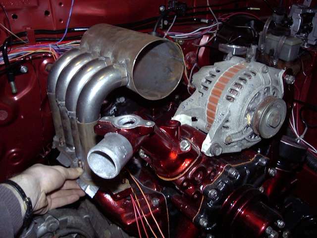
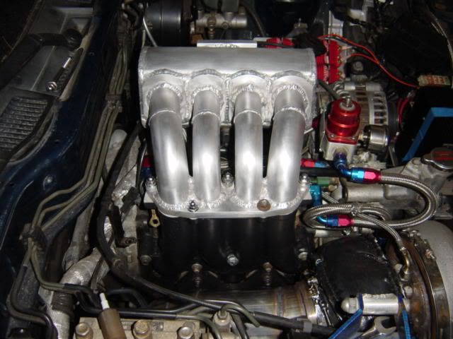
This is a custom upper designed to mate to a 6 port NA 2nd gen lower for my Project Tina. Offhand, ~20CM long runners, 1.5" secondary, 1.25" primary, 9" x 4" plenum. The throttle body is a 75MM Edlebrock unit. The engine has a small bridgeport and this setup made just over 400 RWHP on a GT40R at 13 PSI. High boost setting is 16 PSI but has not been dyno'ed yet. 500HP?


http://www.aaroncake.net/rx-7/projec...an112006-2.htm
This is a custom upper designed to mate to a 6 port NA 2nd gen lower for my Project Tina. Offhand, ~20CM long runners, 1.5" secondary, 1.25" primary, 9" x 4" plenum. The throttle body is a 75MM Edlebrock unit. The engine has a small bridgeport and this setup made just over 400 RWHP on a GT40R at 13 PSI. High boost setting is 16 PSI but has not been dyno'ed yet. 500HP?
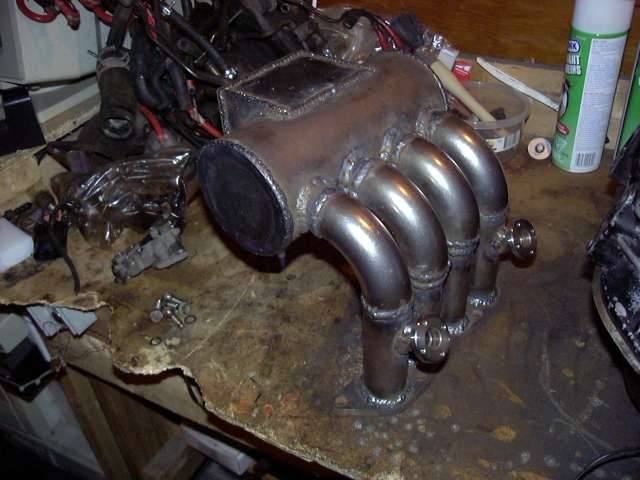
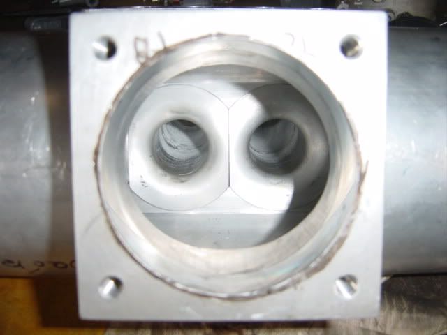
I have some better pictures on my other laptop showing the machined inboard velocity stacks. I used them as I felt that turbulence could occur with just having the port rounded out. Plus there would be even flow all across the runners. I didn't try to make the welds really nice as I didn't want any penetration. Welding .065" aluminum without penetration is pretty hard.
Anyway, it doesn't look horrible but it was made to perform and it has made a great improvement over the factory UIM! I spent too much time making everything equal length, uniform, and went through every runner to make sure there was no hanging welds. Drive-ability wasn't impeded at all for me. The 3.5" q45 gave me no issues...

Anyway, it doesn't look horrible but it was made to perform and it has made a great improvement over the factory UIM! I spent too much time making everything equal length, uniform, and went through every runner to make sure there was no hanging welds. Drive-ability wasn't impeded at all for me. The 3.5" q45 gave me no issues...
Rotary Enthusiast
Joined: Oct 2007
Posts: 799
Likes: 3
From: Plymouth, MN
hehe I know what you mean, my project just never seems to stop
by chance how did that thing spool? sounds like my t70 .96 backside and half bridge (s5 motor though). Only difference besides motor is I have a 4" downpipe to 3" all the way back. I wonder how those 10:1 rotors help out
by chance how did that thing spool? sounds like my t70 .96 backside and half bridge (s5 motor though). Only difference besides motor is I have a 4" downpipe to 3" all the way back. I wonder how those 10:1 rotors help out
BTW...some amazing manifolds on this thread...rotary ****...yum!
Chris
Rotary Enthusiast
Joined: Oct 2007
Posts: 799
Likes: 3
From: Plymouth, MN
I have some better pictures on my other laptop showing the machined inboard velocity stacks. I used them as I felt that turbulence could occur with just having the port rounded out. Plus there would be even flow all across the runners. I didn't try to make the welds really nice as I didn't want any penetration. Welding .065" aluminum without penetration is pretty hard.
Anyway, it doesn't look horrible but it was made to perform and it has made a great improvement over the factory UIM! I spent too much time making everything equal length, uniform, and went through every runner to make sure there was no hanging welds. Drive-ability wasn't impeded at all for me. The 3.5" q45 gave me no issues...
Anyway, it doesn't look horrible but it was made to perform and it has made a great improvement over the factory UIM! I spent too much time making everything equal length, uniform, and went through every runner to make sure there was no hanging welds. Drive-ability wasn't impeded at all for me. The 3.5" q45 gave me no issues...
chris
InsaneRotaries.com
Joined: Feb 2002
Posts: 2,748
Likes: 0
From: Westchester, NY
Grand Dad's (Phil Laird) 13b cast runners go for $2000 AUD and his 20b units are around $2275 AUD. A few days ago I spoke to Marco at Magnus Motorsports and he's in the process of designing an intake manifold for both 13b's & 20b's.. Unfortunately he doesn't have an exact release date, but I know it'll be a billet piece.

Thread Starter
Joined: Jul 2002
Posts: 1,723
Likes: 1
From: Indianapolis
I know their manifolds are well respected in the 4G63 world, so i'd love to see something from them for our motors.

I have some better pictures on my other laptop showing the machined inboard velocity stacks. I used them as I felt that turbulence could occur with just having the port rounded out. Plus there would be even flow all across the runners. I didn't try to make the welds really nice as I didn't want any penetration. Welding .065" aluminum without penetration is pretty hard.
Anyway, it doesn't look horrible but it was made to perform and it has made a great improvement over the factory UIM! I spent too much time making everything equal length, uniform, and went through every runner to make sure there was no hanging welds. Drive-ability wasn't impeded at all for me. The 3.5" q45 gave me no issues...
Anyway, it doesn't look horrible but it was made to perform and it has made a great improvement over the factory UIM! I spent too much time making everything equal length, uniform, and went through every runner to make sure there was no hanging welds. Drive-ability wasn't impeded at all for me. The 3.5" q45 gave me no issues...
Almost reminds me of a RE upper those work well, just need to be cleaned up inside and essentially a pretty similar design.
~S~