
Critique my ignition/AFR

Critique my ignition/AFR
Im trying to present it in the easiest way possible for quickest comments. Please dont spare my feeling if anything looks wrong. I would rather have a good running machine than an ego. ;-)
Info:
stock ports reman 13B 40K miles on it
GT35R t4 Divided aspec kit
Pre turbo WI dudemaaaansownrx7 kit
PowerFC boost controller kit and denso 3 bar sensor
550/1680 inj supra pump
target: beat my brother's 2010 GTR in 1/4 mile and/or autox
10 second 1/4
PowerFC 0-8000RPM
PIM 1000-30000 PIM
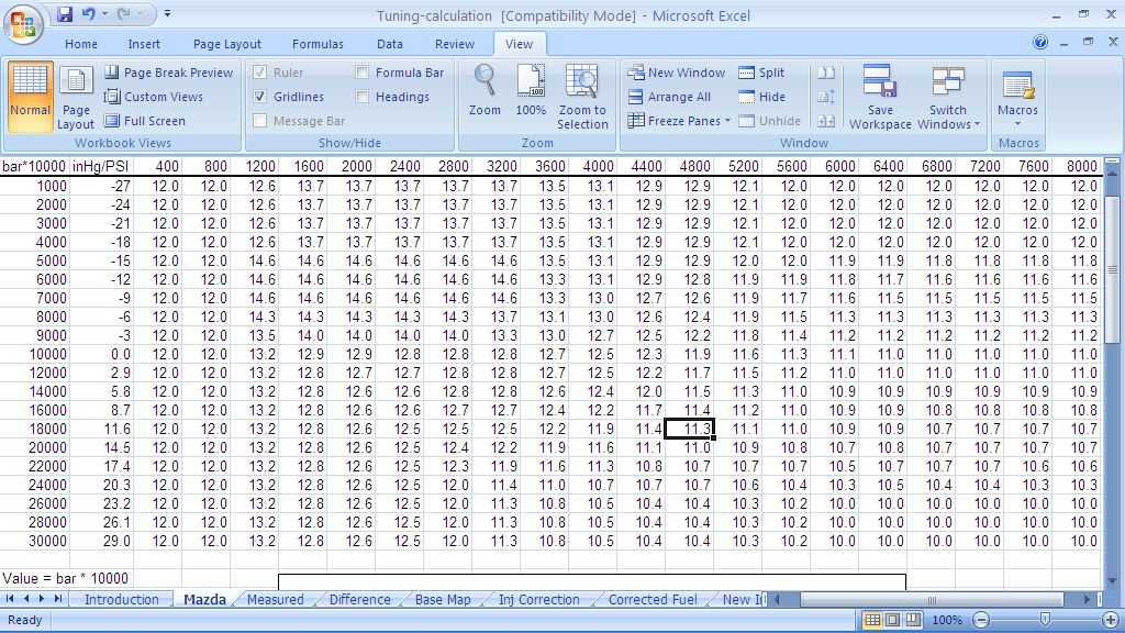
Here is my desired AFR target for each fuel cell
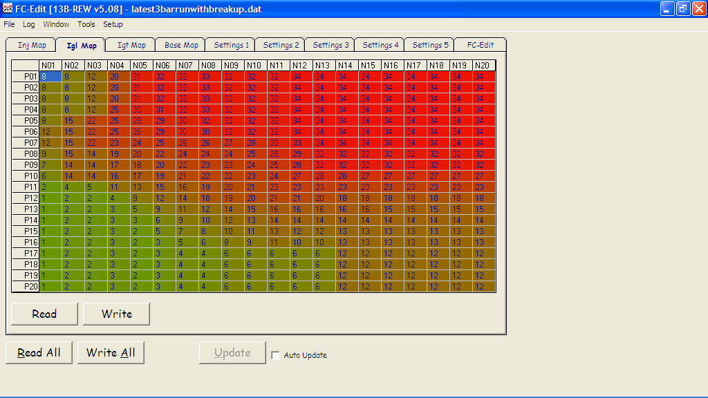
Ignition Leading (from aspec supplied map)
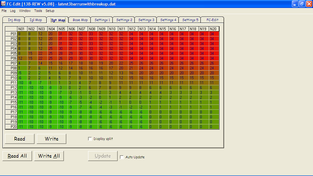
Ignition Trailing (from aspec supplied map)
Quick example of run
Info:
stock ports reman 13B 40K miles on it
GT35R t4 Divided aspec kit
Pre turbo WI dudemaaaansownrx7 kit
PowerFC boost controller kit and denso 3 bar sensor
550/1680 inj supra pump
target: beat my brother's 2010 GTR in 1/4 mile and/or autox
10 second 1/4
PowerFC 0-8000RPM
PIM 1000-30000 PIM
Here is my desired AFR target for each fuel cell
Ignition Leading (from aspec supplied map)
Ignition Trailing (from aspec supplied map)
Quick example of run
Everything looks "good" to me. It would be best to play on a dyno to see where MBT is. Anyway, I'm brave enough to start the critiquing so here's my advice.
1) Knock values above 40 is something to start worrying about. Many cars can deviate from this rule if they have unusual knock values. I try doing some smooth free revving in neutral and vacuum driving while logging knock values. If you have an exceptionally noisy engine or a strange knock sensor you'll see it in these cells.
2) I'm sure you could squeeze a bit more power adjusting timing a little bit but I wouldn't do it at all/too much as you're most likely don't have access to a dyno.
3) Again, you could pick up more power playing with leaner AFR's if you have stable and or very good IAT values.
That's all! If everything seems good from the seat of the pants and it's been like this for awhile with no problems you might best stick with what you have. Just keep logging as this is the time of the year when people start blowing motors
-Lance Mayhon
Freelance Motorsports
I blew my motor 10 years ago at this time. good recommendation there.
Not looking to push the top end horsepower, its plenty for me for now. I now have to focus on getting my wastegate to behave. its building 26 psi before the car fuel cuts. (posted that video in 3rd gen) so i cant really get consistent tuning done until i can actually control my boost.
I really appreciate the feedback. Im building the car to beat my brother's 2010 GTR and its not going to be easy haha
rat ta tat tat
Joined: Aug 2012
Posts: 153
Likes: 0
From: pinwheel galaxy
Is that 3rd Gear??
I would suggest using 4th gear. 3rd is going through the cells too fast and its less accurate. You really wana load it up. Find a nice safe road with no traffic, cross roads or police, as you will be approaching 150mph. Be safe!!!
You have some a/f dips into the 9's , shoot for 10.5-10.8 which is still pretty fat and you should pick up power.
Smoothe out the timming some,p17n13 area, that drop with all those 6's can be smoothed out.
If you wana beat a modded GTR you might need a bigger turbo.
why would he need a bigger turbo to beat a GTR? it's 485-530 brake horsepower? and 1000lbs heavier.
the 35R can put out the same horsepower, only difference will be traction where the FD will be very difficult to keep on the pavement without any traction controls where the GTR has AWD and a sophisticated traction control system.
the 35R can put out the same horsepower, only difference will be traction where the FD will be very difficult to keep on the pavement without any traction controls where the GTR has AWD and a sophisticated traction control system.


Based only on what you have posted, there's not a whole lot more you can do with it unless you go put it on a dyno and start trying different AFR and timing combinations to see what happens.
Trending Topics
Except timing should increase after maximum torque to generate more power at lower egts!
Flat line timing is like mechanical distributors did and is soooo outdated and power wasteful.
Flat line timing is like mechanical distributors did and is soooo outdated and power wasteful.
how much of an increase would i want to set the timing when i would first start adjusting it? Im obviously assuming the smallest units possible, but i want to clarify what typically happens after max torque.
Timing is probably my weakest area of knowledge on the car.
rat ta tat tat
Joined: Aug 2012
Posts: 153
Likes: 0
From: pinwheel galaxy
Here is an example of what chuck is talking about.
N rows are 400-8000
p rows are 1000-24000
Stock 2 bar map
Notice how from after N16 timming climbs a good bit. Most stock intake manifold REW's running that turbo begin to lose tq after 6,500 rpm. As this happens you can incress timming. Gaining hp power compared to running flat TQ, you have fully adjustable timming, take advantage of it..
Agian this is an example to show an incress after peak TQ, don't use these valuse, find what works best for your car.
rat ta tat tat
Joined: Aug 2012
Posts: 153
Likes: 0
From: pinwheel galaxy
why would he need a bigger turbo to beat a GTR? it's 485-530 brake horsepower? and 1000lbs heavier.
the 35R can put out the same horsepower, only difference will be traction where the FD will be very difficult to keep on the pavement without any traction controls where the GTR has AWD and a sophisticated traction control system.
the 35R can put out the same horsepower, only difference will be traction where the FD will be very difficult to keep on the pavement without any traction controls where the GTR has AWD and a sophisticated traction control system.
Ok no more bench racing, back to tuning
[QUOTE=Knockers;11235327]Here is an example of what chuck is talking about.
N rows are 400-8000
p rows are 1000-24000
Stock 2 bar map
Notice how from after N16 timming climbs a good bit. Most stock intake manifold REW's running that turbo begin to lose tq after 6,500 rpm. [QUOTE]
That is a good example. An engine with smaller to stock ports would need more timing added past max torque.
If you tune AFRs flat across the rpm columns, max torque will be around the cells with the most fuel usage. If you make a graph of your fuel curve, that will be close to your torque curve.
Thanks guys again! And yes my brothers gtr is modded. Already put down 520+ to the wheels (all four lol) so it's not looking good for me. But I believe in the rx7. We are both aiming for mid to high 10 second runs. I already have drag tires on order.
The only limitation he has is we agreed I'm allowed to run drag tires while he runs street tires.
Fun times regardless of outcome. :-) but I want to polish my tail lights so my brother can see them clearly. I'll keep crunching on tuning until then
The only limitation he has is we agreed I'm allowed to run drag tires while he runs street tires.
Fun times regardless of outcome. :-) but I want to polish my tail lights so my brother can see them clearly. I'll keep crunching on tuning until then


Now, consistently hitting 10:1 or 9.7:1 under normal WOT conditions (not heatsoaked or something) is excessive and I'm definitely with you on that. On the other hand, you don't want you have a problem when the seasons change. In my experience, the best you can hope for is +/- 0.5:1 if you say tuned it in summer and then make some tweaks in the winter time.
If you are willing to have maps for different seasons you can optimize it more for the individual conditions.
The stock PFC "Air Temp vs Inj" table is not set up for linearity. Thus your AFRs will vary between seasons. You can find the data on the internet and then reset the table.
Then AFR tune in summer or the winter extreams. When the season changes, recheck your AFRs to see if the table was accurate for your setup. If not make the ball park table correct so that the table will be linear over the year.
Moving the air temp sensor to an IC outlet or the TB elbow will also help as it will be more accurate there.
Getting a fast reacting air temp sensor for a Triumph Motorcycle is another plus.
The above advice is based on the fact that he has water. Even with a variance of 1.0 afr. With water in there he will be fine. In saying that my testing has never shown a variance of 1.0 afr if all the temp compensation maps are setup correctly. 0.2-0.5 afr is usually where it ends up differing with some good maps.
I live in Michigan so I'm basically grounded for the season. Anything less than 65degrees and I don't want to monkey with it. I blew the engine 10 years ago when I was doing spirited driving in November. But we found out the wastegate was welded shut on a stock ecu. Regardless, it's made me apprehensive of colder weather
Chuck and all,
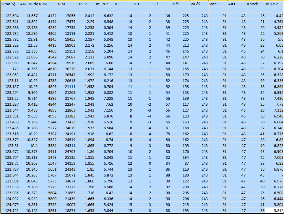
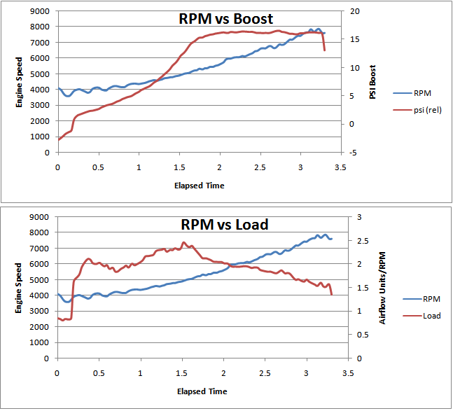
I did a ratio calculation on my last run of the season. I lost the clutch in 3rd gear so im not going to adjust from this data but i wanted to verify some numbers.
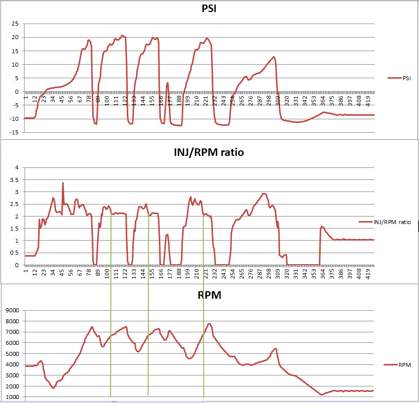
PSI and RPM are self expanatory.
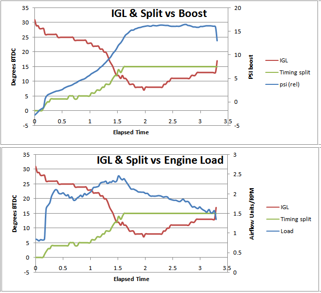
INJ/RPM ratio was calculated using a formula i created. I used the following variables:
InjFrPr - Primary Fuel Injectors Pulse in Milliseconds
InjFrSc - Secondary Fuel Injectors Pulse in milliseconds
PriCC - my primary injectors CC 550cc
SecCC - my secondary injectors CC 1680cc
RPM - engine RPM
InjFrPr*PriCC - to convert milliseconds into fuel used ratio to add with secondaries
InjFrSec*SecCC - to convert milliseconds into fuel used ratio to add with primaries
Added both of those and divided by RPM
The green lines are what i assume are the drop off points after max torque? it was consistently 6600 RPM and at this current boost control setting 17.5PSI. Am i correct in my logic for advancing timing?
I did a ratio calculation on my last run of the season. I lost the clutch in 3rd gear so im not going to adjust from this data but i wanted to verify some numbers.
PSI and RPM are self expanatory.
INJ/RPM ratio was calculated using a formula i created. I used the following variables:
InjFrPr - Primary Fuel Injectors Pulse in Milliseconds
InjFrSc - Secondary Fuel Injectors Pulse in milliseconds
PriCC - my primary injectors CC 550cc
SecCC - my secondary injectors CC 1680cc
RPM - engine RPM
InjFrPr*PriCC - to convert milliseconds into fuel used ratio to add with secondaries
InjFrSec*SecCC - to convert milliseconds into fuel used ratio to add with primaries
Added both of those and divided by RPM
The green lines are what i assume are the drop off points after max torque? it was consistently 6600 RPM and at this current boost control setting 17.5PSI. Am i correct in my logic for advancing timing?
Those green lines are probably correlated with your peak torque or a few hundred rpm after it. Intuitively it makes sense, and we know anecdotally that single turbo rotaries often make peak torque that high depending on a number of factors. But we can't be sure. So yes, you could probably start advancing timing after that, or maybe a little before--say from 6000rpm to max rpm.
just a little aside about your method...
I see what you're doing here with the INJ vs rpm calculation. Airflow/rpm is actually a pretty standard basis for calculating charging efficiency and load. A lot of Japanese stock ECUs use this method. For example, we have this section in the 1984 Rx-7 GSL-SE training manual which describes the basic fuel injection calculation:
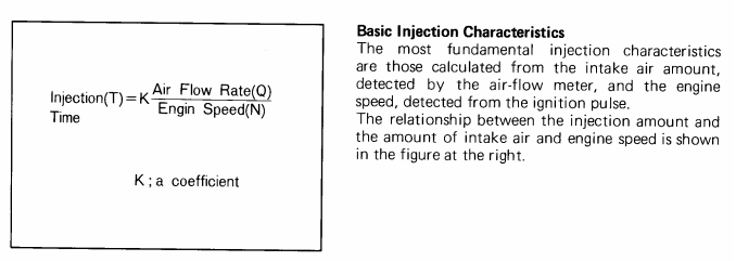
The problem here is that we don't have a MAF sensor to measure airflow and thus charging efficiency, and we don't have a model to back calculate charging efficiency either. You gotta work with what you have though.
What I would do is take your wideband reading, convert to lambda (also known as "Excess air ratio"), and back calculate to airflow. If you have the volume fuel flow, which you have already estimated, and you have the air/fuel ratio (lambda, aka excess air ratio), you can calculate the volume air flow. When you have the volume airflow you could calculate roughly the charging efficiency. Then you can have your timing curve follow that. Every 96+ OBDII car reports a type of charging efficiency calculation over the OBD port.
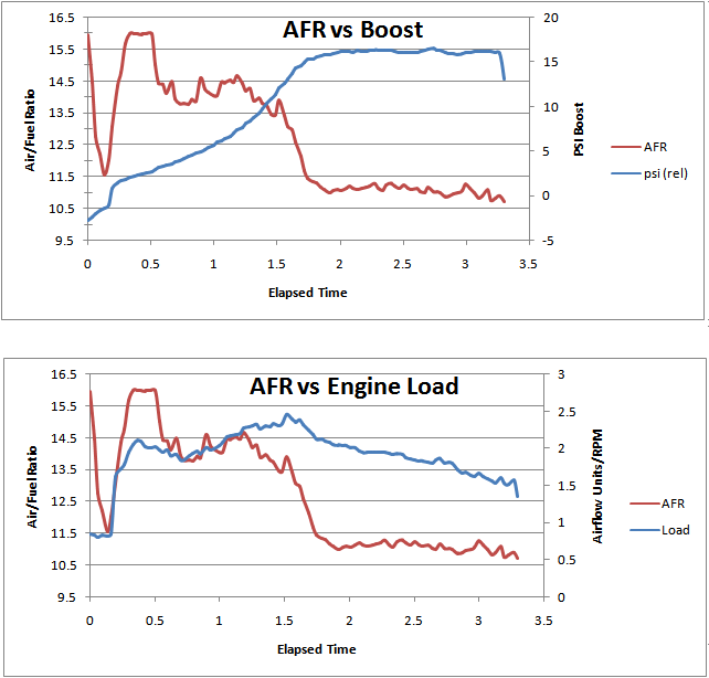
Here is a real world example to perhaps help you (or maybe even confuse you). This is from some road tuning I did a couple years ago on a 2005 STi with 18G turbo. Like most newer cars, it has a manifold pressure sensor and a MAF sensor. I put some graphs together at the time and you might find them useful.
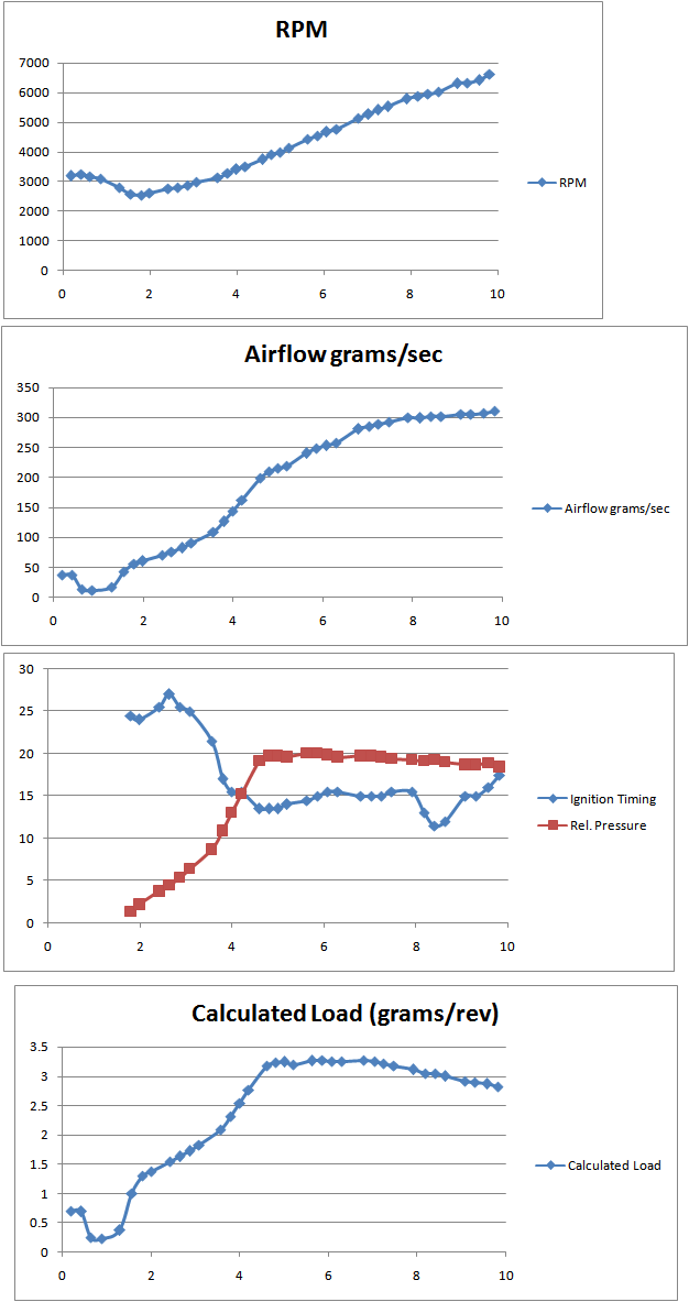
There are a couple dips in the timing curve as rpms increase, but iirc it may have been the ECU reacting to the knock sensor reading. Notice that this is based on mass air flow, but you should get the same basic trend if you used volume airflow.
just a little aside about your method...
I see what you're doing here with the INJ vs rpm calculation. Airflow/rpm is actually a pretty standard basis for calculating charging efficiency and load. A lot of Japanese stock ECUs use this method. For example, we have this section in the 1984 Rx-7 GSL-SE training manual which describes the basic fuel injection calculation:
The problem here is that we don't have a MAF sensor to measure airflow and thus charging efficiency, and we don't have a model to back calculate charging efficiency either. You gotta work with what you have though.
What I would do is take your wideband reading, convert to lambda (also known as "Excess air ratio"), and back calculate to airflow. If you have the volume fuel flow, which you have already estimated, and you have the air/fuel ratio (lambda, aka excess air ratio), you can calculate the volume air flow. When you have the volume airflow you could calculate roughly the charging efficiency. Then you can have your timing curve follow that. Every 96+ OBDII car reports a type of charging efficiency calculation over the OBD port.
Here is a real world example to perhaps help you (or maybe even confuse you). This is from some road tuning I did a couple years ago on a 2005 STi with 18G turbo. Like most newer cars, it has a manifold pressure sensor and a MAF sensor. I put some graphs together at the time and you might find them useful.
There are a couple dips in the timing curve as rpms increase, but iirc it may have been the ECU reacting to the knock sensor reading. Notice that this is based on mass air flow, but you should get the same basic trend if you used volume airflow.
Great catch. I havent ever owned a car with a mass air sensor that I wanted to upgrade so I forgot the difference.
I always appreciate your insight. Ill be playing with that information and calculate the air flow from there
My next adventure is the cosmo intake and port matching so volumetric efficiency is of great interest to me. I hear the upper intake manifold and lower are great for increased performance in the lower end.
Yes, when your airflow / rpm ratio peaks, generally speaking you want your timing curve to be at its most retarded point. Here's another example to consider. This was posted by RotaryRocket88 I think.
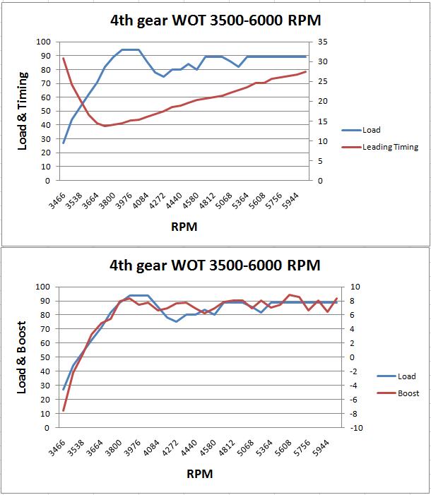
This is data recorded from his 2nd gen turbo convertible. He is using the Rtek 2.1 ECU, which is a programmable stock ECU. You can adjust timing based on the load calculation (directly related to airflow/rpm) or you can turn on boost-based timing. I have assisted a lot of Rtek guys with both types of timing control. Due to limitations in the stock airflow meter, load-based timing is limited for this platform. You can't rescale the airflow vs voltage curves like you can on newer engines (Rx-8 for example).
Now to further enlighten you, let's compare a load-based (load ~ airflow/rpm) timing map to a boost-based timing map. I will use Rtek examples here again, because it illustrates this concept. Below are the Mazda OEM leading and stock split maps on a 1987-1988 FC Turbo II. The Y axis is the load calculation. I don't know the exact physical units, but it is proportional to airflow/rpm.


now below are boost-based timing maps I made that a lot of Rtek guys are using as their starting point.


They key to remember here is that boost does not automatically = engine load... it goes back to discussions about airflow vs pressure.
This is data recorded from his 2nd gen turbo convertible. He is using the Rtek 2.1 ECU, which is a programmable stock ECU. You can adjust timing based on the load calculation (directly related to airflow/rpm) or you can turn on boost-based timing. I have assisted a lot of Rtek guys with both types of timing control. Due to limitations in the stock airflow meter, load-based timing is limited for this platform. You can't rescale the airflow vs voltage curves like you can on newer engines (Rx-8 for example).
Now to further enlighten you, let's compare a load-based (load ~ airflow/rpm) timing map to a boost-based timing map. I will use Rtek examples here again, because it illustrates this concept. Below are the Mazda OEM leading and stock split maps on a 1987-1988 FC Turbo II. The Y axis is the load calculation. I don't know the exact physical units, but it is proportional to airflow/rpm.
now below are boost-based timing maps I made that a lot of Rtek guys are using as their starting point.
They key to remember here is that boost does not automatically = engine load... it goes back to discussions about airflow vs pressure.
I went ahead and made a spreadsheet that takes injector pulsewidth, RPM, and AFR to calculate engine load. Engine load is a unitless relationship between airflow (back-calculated from lambda and injector pulsewidth) and rpm. When I say unitless, I mean that the calculations are simplified and the units are not really in exact physical quantities. Basically, the more air entering relative to the engine speed the higher the engine load. There are other types of load calculations that compare measured engine airflow to theoretical airflow at standard conditions; I deliberately avoided this for simplicity's sake.
You can use this tool to visualize your fuel and timing curves. You can also get an idea where the engine is most vulnerable to knock--the highest load areas
https://docs.google.com/open?id=0B_j...GRqdnlCZ3c3STQ
Download the spreadsheet and open it up in Excel. It has instructions--basically you put in your injector sizes, and carefully paste data from the FC-Edit .txt file. Then it spits out a bunch of graphs for you. Let me know if you can think of any improvements or bugfixes for it. Here's some data from a single turbo setup.