
Rtek Rtek AFM delete?


i think he's saying, we all wanted laptop supported tuning, and you knew about the emulator, but didn't tell anyone and lets us figure it out by ourselves... which is kinda true ain't it?
what would it take for me to be able to look at the rtek programming, and be able to alter the forumal used for AFM calculations based on Air temp sensor, and flapper door? your personal dev kit? is the coding hexidecimal, java, c++, binary even?, some form of basic or something completely diffrent? i just wanna help. i got skillz. i;m not looking to sell your ideas or steal them for myself, just make them better, and put more man power at these tasks at hand.
what would it take for me to be able to look at the rtek programming, and be able to alter the forumal used for AFM calculations based on Air temp sensor, and flapper door? your personal dev kit? is the coding hexidecimal, java, c++, binary even?, some form of basic or something completely diffrent? i just wanna help. i got skillz. i;m not looking to sell your ideas or steal them for myself, just make them better, and put more man power at these tasks at hand.
I did know about the emulator. It's a support thing. It's not easy to set up. *I* can't even get the garnet emu working right. I'm still using the palm OS 3/4 simulator because no matter what I do, the garnet emu crashes or won't connect to the serial port. I don't condone using the emulator because I already have enough workload helping people fix problems with their car that have nothing to do with the Rtek.
It's written in assembly. Unless you have intimate knowledge of how the processor works, you aren't going to be making any changes without spending an extensive amount of time learning the language, the architecture and schematic. And once you learn that you'd need to understand how the program actually works before you can make any changes that won't break anything. Is it impossibly? Certainly not. But are you willing to work at it for 6 months before you can make a change?
I am all for "community" help in making things better. I had given someone here full access to the communication protocol (which we have NEVER done), because he was interested in the web interface and I wanted to encourage the community. But nothing came of it. Unfortunately, giving free access to the code is like asking home depot to borrow tools for free and without a deposit. It's just not smart for business.
With that said, we are currently in talks with a company that could supply a Rtek version of their comprehensive PC based ECU editing software.
I encourage people to explore the MAS options. It's not impossible. I'm just saying, even knowing what we know, we looked at it and thought it was not worth it. So to me, that says someone with limited knowledge and no way to edit code is probably just wasting his time. I'm not trying to be a party pooper, just expressing my "more knowledgeable on the subject than the average guy" opinion on the idea. No one is stopping anyone from trying anything. Maybe you'll come up with something we didn't think of. I will try to help in any way I feel is going to be productive.
I did know about the emulator. It's a support thing. It's not easy to set up. *I* can't even get the garnet emu working right. I'm still using the palm OS 3/4 simulator because no matter what I do, the garnet emu crashes or won't connect to the serial port. I don't condone using the emulator because I already have enough workload helping people fix problems with their car that have nothing to do with the Rtek.
It's written in assembly. Unless you have intimate knowledge of how the processor works, you aren't going to be making any changes without spending an extensive amount of time learning the language, the architecture and schematic. And once you learn that you'd need to understand how the program actually works before you can make any changes that won't break anything. Is it impossibly? Certainly not. But are you willing to work at it for 6 months before you can make a change?
I am all for "community" help in making things better. I had given someone here full access to the communication protocol (which we have NEVER done), because he was interested in the web interface and I wanted to encourage the community. But nothing came of it. Unfortunately, giving free access to the code is like asking home depot to borrow tools for free and without a deposit. It's just not smart for business.
With that said, we are currently in talks with a company that could supply a Rtek version of their comprehensive PC based ECU editing software.
I encourage people to explore the MAS options. It's not impossible. I'm just saying, even knowing what we know, we looked at it and thought it was not worth it. So to me, that says someone with limited knowledge and no way to edit code is probably just wasting his time. I'm not trying to be a party pooper, just expressing my "more knowledgeable on the subject than the average guy" opinion on the idea. No one is stopping anyone from trying anything. Maybe you'll come up with something we didn't think of. I will try to help in any way I feel is going to be productive.
I encourage people to explore the MAS options. It's not impossible. I'm just saying, even knowing what we know, we looked at it and thought it was not worth it. So to me, that says someone with limited knowledge and no way to edit code is probably just wasting his time. I'm not trying to be a party pooper, just expressing my "more knowledgeable on the subject than the average guy" opinion on the idea. No one is stopping anyone from trying anything. Maybe you'll come up with something we didn't think of. I will try to help in any way I feel is going to be productive.
The problem with the afm, is that it actually restrict air flow, but rather it just doesn't measure over a certian limit. Some people don't understand this yet. I do.
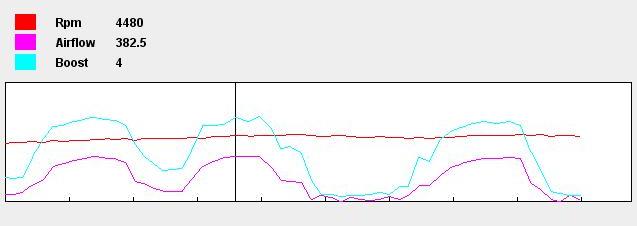
i think it would be easier to make a converter that replaces the AFM with a MAP sensor. this is a pic posted by arghx in another thread, look at how closely the MAP signal follows airflow:
it could probably be done with an SAFC that can invert the MAP 0-5V signal to the AFM 4V-0V signal, and then smooth it out with the rtek 2. I would try it myself, but i dont have a stock ecu FC anymore
can someone make a longer log and compare the boost sensor to AFM signal and see how much they differ? You could just look at the log and be able to figure out what correction you would need to put in the RTEK
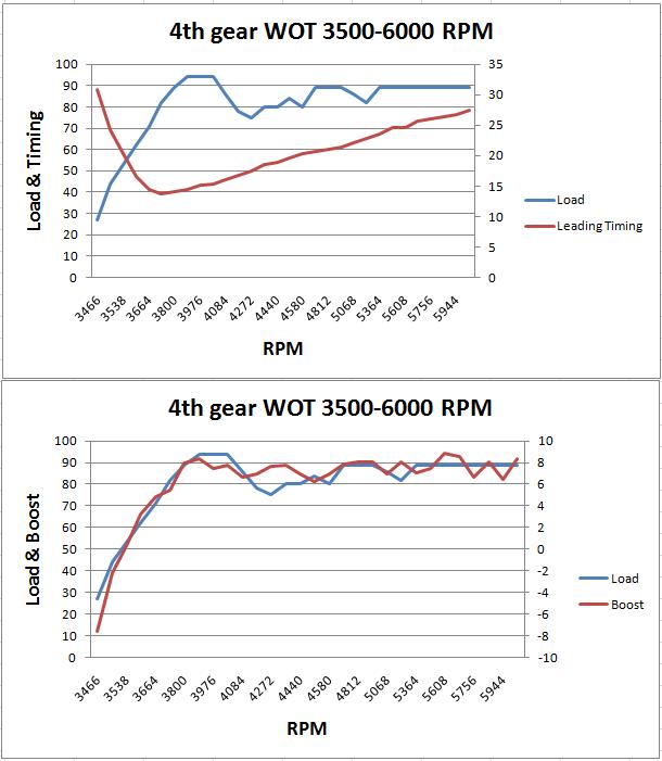
Load is calculated, via a formula based on map sensor, Rpm, and throttle sensor(?), maybe others that effect the way it's calculated.
Airflow is just that, an amount of air, whether CFM, or cubic cm/min. it starts low and only gets higher the more rpm/boost is given under WOT.
MAP signal on a boosted motor will begin at 0 psi under WOT, and gain to maximum boost pressure, and then slighly fall off in later rpm.
it's all the noobs trying to jump aboard this "we can do it ourselves" train that makes the people on the train get held back from actually getting something done. Thats why alot of the people that work on things for the rtek that is not supported by DTI usually keep it hush hush until they have it completely figure'd out.
( POSE EMU as an example)
If i was to have posted about how close i was to actually getting it to work , without it working, there woulda been dozens of people... doing all my work up to the point i was at, and then trying just senseless steps and complishing nothing.
It's like the blind thinking they can build a lego castle without directions just because the next guy can do it with directions/vision. Which all comes back to, if you have to ask, you shouldn't be ******* with it.
There are mechanical solutions to this.
Simply introducing a "controlled leak" into the system will move the range the AFM reads down, essentially giving you more headroom. Though you'll lose accuracy down low due to the slower velocity of air. So you need to put a flapper on the bypass that only opens when the velocity gets higher.
Simply introducing a "controlled leak" into the system will move the range the AFM reads down, essentially giving you more headroom. Though you'll lose accuracy down low due to the slower velocity of air. So you need to put a flapper on the bypass that only opens when the velocity gets higher.
Sounds like a solid plan for me, thread closed.

That might be hard to tune due to the abruptness. A lightly sprung flapper would "blend" better. You could certainly get into more advanced setups...like using a drive-by-wire throttle to adjust bypass air on the fly.. heh
Controlled leak? Wouldn't that make the AFM read lower? Thus compounding the problem? I believe the flapper actually has to open in order for teh car to run too... Raising fuel pressure and 'Mod'ing the AFM seem like better alternatives.
Yes it would read lower. The idea is you allow an alternate path for the air to flow thus moving the output range of the sensor to a different range of flow. Now the sensor has resolution at higher airflow which was the original complaint...it also allows less restrictive flow overall.
lol a fly by wire throttle body would have to be pretty small.
What about having TWO afms, one setup like a wide band(or external sensor under rtek)
And then just wire the two output wires in serias. thus doubling the voltage, and therefore making the ecu think it's readying half of what each afm is flowing. nope. that's dope talk there.
What about having TWO afms, one setup like a wide band(or external sensor under rtek)
And then just wire the two output wires in serias. thus doubling the voltage, and therefore making the ecu think it's readying half of what each afm is flowing. nope. that's dope talk there.
You're way off. WAY.. Think about that you are saying.
Load is calculated, via a formula based on map sensor, Rpm, and throttle sensor(?), maybe others that effect the way it's calculated.
Airflow is just that, an amount of air, whether CFM, or cubic cm/min. it starts low and only gets higher the more rpm/boost is given under WOT.
MAP signal on a boosted motor will begin at 0 psi under WOT, and gain to maximum boost pressure, and then slighly fall off in later rpm.

as simple as i can put it.
the stock ecu doesn't depend on rpm to decide injector"on time"(although it does in away)
With a map sensor, it would have to read the rpm and take that into account. otherwise you would have the same aounmt of fuel at 8psi, at 4 -6k rpm. and then less fuel after that.
the stock ecu doesn't depend on rpm to decide injector"on time"(although it does in away)
With a map sensor, it would have to read the rpm and take that into account. otherwise you would have the same aounmt of fuel at 8psi, at 4 -6k rpm. and then less fuel after that.
Yes, you are missing something, though maybe it's not so obvious.
So you have two readings:
Air flow: the *volume* of air going in
MAP: (along with air temp) the *density* of the air going in.
In order to calculate how much fuel to inject, the ECU has to know the MASS of the air. Both volume and density are required to calculate mass. m = v*d
With airflow, we know the volume, but not how dense the air is. You need a lot more fuel to be at the right AFR for 1 cu ft of air at 15 PSI than 1cu ft of air at 5 psi.
With MAP, we know the density but not how much air is at that density. How much fuel do you need for proper AFR at 15 psi when you don't know if it's 1cu ft or 10cu ft of air?
So if you remove one of the sensors, you take away the ability to calculate density and therefore loose all hope of properly fueling the engine.
And for completeness, Speed Density systems use a theoretical airflow number based on the volume of the engine, RPM and the TPS position. This eliminates the need to measure air with an airflow meter. But this also makes the system not adaptable to changes to the engine that result in deviations from the theoretical airflow (such as adding a free flowing exhaust) without "telling" the ECU. In order to have a proper SD system, you need to fully characterize the airflow through a given engine in a given configuration. No easy task without an engine dyno and good test equipment.

Senior Member


Joined: Aug 2010
Posts: 415
Likes: 8
From: Treasure coast
This eliminates the need to measure air with an airflow meter. But this also makes the system not adaptable to changes to the engine that result in deviations from the theoretical airflow (such as adding a free flowing exhaust) without "telling" the ECU. In order to have a proper SD system, you need to fully characterize the airflow through a given engine in a given configuration. No easy task without an engine dyno and good test equipment.

exactly.
You are going to get readings every 250 RPM from idle to redline, and for each RPM, every 10% throttle from 0 tp 100% in a static load condition while accurately measuring air *mass* on the street? I don't think so. The UEGO is useless, we don't care about AFRs, we care about air mass.
You are going to get readings every 250 RPM from idle to redline, and for each RPM, every 10% throttle from 0 tp 100% in a static load condition while accurately measuring air *mass* on the street? I don't think so. The UEGO is useless, we don't care about AFRs, we care about air mass.

I win
Joined: Jun 2004
Posts: 1,875
Likes: 2
From: NJ
I believe I made a post a while ago in the 2nd gen section about adding in airflow by introducing a Y pipe at the turbo... one end with the afm and the other with a filter on it and then using a safc to correct the signal the afm see's. Only thing I have a problem with even trying this is that by making adjustments with the safc it will change the timing in the ecu. I just think it would be hard to accomplish something like this it would take a lot of time to get it right.
It would be nice to see the afm somehow get deleted.
I would like to upgrade to a different ecu in my FC have been waiting to see if rtek can delete the afm, the megasquirt system can be built for about the same price so I am on the fence between the 2.
It would be nice to see the afm somehow get deleted.
I would like to upgrade to a different ecu in my FC have been waiting to see if rtek can delete the afm, the megasquirt system can be built for about the same price so I am on the fence between the 2.
Senior Member
Joined: Aug 2010
Posts: 415
Likes: 8
From: Treasure coast

Shouldn't boost be in the equation also. Maybe a simpler solution is a boost sensitive "controlled leak" - more boost, more bypass air.
You guys ever thought about selling the Rtek line? If it puts you upside down financially to better your product, wouldn't the smart decision be to offer the business to someone willing to invest the money in development costs? It almost sounds to me like it's becoming more like you're hemorrhaging money rather than making it, and no dis-respect at all, but you sound tired of supporting us picky Rx'ers 
So why not make it someone else's problem? I for one would hate to see you guys sell the line, as you have excellent customer support in my experience.
I suppose it also boils down to the fact that whoever would take the line, would take quite a bit of loss as well... As the demand for this product is far from where it would need to be to make this even a logical research endeavor...
Business sucks... that simple.
That being said, you guys have made a great product. So great, that you left your customers wanting you to do more
Senior Member
Joined: Aug 2010
Posts: 415
Likes: 8
From: Treasure coast
That's what I meant. The boost would actuate a device/valve (what ever you want to call it) allowing air to circumvent the flapper. As boost increases, circumvented air flow would increase in proportion to boost increase. One can set @ what boost to open and the rate of open mechanically.
Last edited by Clubuser; Feb 28, 2011 at 06:24 PM.
I win
Joined: Jun 2004
Posts: 1,875
Likes: 2
From: NJ
If someone has a safc and a Rtek this can be done really easily I think. You just need to make a Y pipe before the turbo have one end setup like normal and on the other end you can start out with using a coupler reducer and use a 1" tube with a filter on the end. Start the car make sure the afm door still functions properly. The safc will be used to trick what the afm see's. As long as the flapper door opens this will work. Then you can keep on trying a bigger tube on the other end of the Y until you know whats sufficient.
My whole thing with this is by making adjustments with the safc the computer will adjust timing to compensate for the changes you make with the safc. As long as you can keep timing stable with the rtek you reduce the risks of damage happening.
here's a link for you to read
http://autospeed.com/cms/title_Airfl...4/article.html
http://autospeed.com/cms/A_2449/article.html