Why Apex Seals Fail
 10-22-09, 10:30 AM
#126
"Elusive, not deceptive!�
Thread Starter
TO all the guys saying they are not seeing a drop in EGT's from water injection. Dont expect one. Water simply eliminates or hugely reduces KNOCK.
My 700rwhp engine on the freeway will go to over 1080 Degrees Celcius. My engine still has excellent compression no problems. 1050 degrees celcius over a short period of time is alittle high, but over a good distance of full power its not uncommon to see high egts.
My 700rwhp engine on the freeway will go to over 1080 Degrees Celcius. My engine still has excellent compression no problems. 1050 degrees celcius over a short period of time is alittle high, but over a good distance of full power its not uncommon to see high egts.
My EGT's run the same and the only negative result so far has been scale-like erosion of the cast iron divided exhaust housing.
It must really be glowing!
Barry
 10-23-09, 04:27 PM
#127
"Elusive, not deceptive!�
Thread Starter
That is hot. Mine are at 750-800C at 2" from exhaust port under full load. I barely get up to 1000C under lean cruise!
Funny my lean cruise is 850�C at 15.5 AFR.
You should try tuning to lower EGTs under load and see how much that helps. It will drop your power a small amount for sure, but it will help durability.
I have tried more and less fuel (10.2-11.8 AFR), and advancing and retarding 3 degrees with little to no effect to the EGT's.
High EGTs will affect every part inside the engine. Yes, the spark plug is hottest part, but it WILL be cooler there as well if you lower your EGTs.
Maybe it would make more sense to you if I referred to it as combustion gas temperature instead of EGTs, and you are just monitoring this CGT from resultant EGTs.
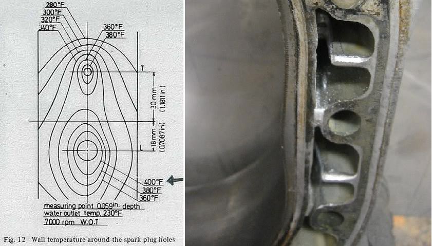
BTW, Mazda documentation shows there is the most heat from the housings being exchanged into the coolant where the peak gas pressure is at (directly between the 3:00 and 6:00 position as viewed from the front with the spark plugs just above and below 3:00 possition). This is why they have more cooling in passage #6 as you show with your test.
The leading spark plug has the highest localized peak surface temperature. It also has a chrome surface that transfers heat very poorly to the steel and then aluminum housing and finally into the coolant.
The chrome surface would protect the plugs from the heat of the "combustion gas temperatures" wouldn't it?
So it is a great idea to try to control the heat of this localized insulated surface from the inside where the heat is coming from, EGTs will guide you.
Funny my lean cruise is 850�C at 15.5 AFR.
You should try tuning to lower EGTs under load and see how much that helps. It will drop your power a small amount for sure, but it will help durability.
I have tried more and less fuel (10.2-11.8 AFR), and advancing and retarding 3 degrees with little to no effect to the EGT's.
High EGTs will affect every part inside the engine. Yes, the spark plug is hottest part, but it WILL be cooler there as well if you lower your EGTs.
Maybe it would make more sense to you if I referred to it as combustion gas temperature instead of EGTs, and you are just monitoring this CGT from resultant EGTs.
BTW, Mazda documentation shows there is the most heat from the housings being exchanged into the coolant where the peak gas pressure is at (directly between the 3:00 and 6:00 position as viewed from the front with the spark plugs just above and below 3:00 possition). This is why they have more cooling in passage #6 as you show with your test.
The leading spark plug has the highest localized peak surface temperature. It also has a chrome surface that transfers heat very poorly to the steel and then aluminum housing and finally into the coolant.
The chrome surface would protect the plugs from the heat of the "combustion gas temperatures" wouldn't it?
So it is a great idea to try to control the heat of this localized insulated surface from the inside where the heat is coming from, EGTs will guide you.
Thanks for your input.
Barry
 [/QUOTE]
10-27-09, 10:20 AM
[/QUOTE]
10-27-09, 10:20 AM
#129
"Elusive, not deceptive!�
Thread Starter
Hey Sean,
I like you idea for extra cooling.
My thought would be to actually warm the area on either side of the plug area and cool the plug boss as much as possible.
Look at your diagram above and think of the temp lines as a topographical map. If we could make it look like steps instead of a hill the apex seals would last a lot longer. That is why the fin would still be connected to the plug boss but the housing area would be allowed to heat up more.
Barry
10-27-09, 11:48 AM
#130
Your getting at less warpage from more even heat displacement, right??? smoother surtface for the seal to go across??
look at the left side compared to the right. think about coolant flow direction and the temp difference. Notice temp lines spread further from the plugs on the left side than the right. now think about what cbr said about the 20b and rear housing cooloimg lines....page 2 i think.
look at the left side compared to the right. think about coolant flow direction and the temp difference. Notice temp lines spread further from the plugs on the left side than the right. now think about what cbr said about the 20b and rear housing cooloimg lines....page 2 i think.
10-28-09, 10:57 AM
#131
"Elusive, not deceptive!�
Thread Starter
Your getting at less warpage from more even heat displacement, right??? smoother surtface for the seal to go across??
look at the left side compared to the right. think about coolant flow direction and the temp difference. Notice temp lines spread further from the plugs on the left side than the right. now think about what cbr said about the 20b and rear housing cooloimg lines....page 2 i think.
look at the left side compared to the right. think about coolant flow direction and the temp difference. Notice temp lines spread further from the plugs on the left side than the right. now think about what cbr said about the 20b and rear housing cooloimg lines....page 2 i think.
He was having boost control problems that kept getting in the way of long term testing of his cooling mods!
CBR's thoughts on keeping it as cool as possible seem to be what we are looking for.
My thoughts are that we should be running as hot as practical. Heat is energy (horsepower) and we want to use it wisely!
Barry
10-28-09, 02:50 PM
#132
...as hot as practical.
What is he doing to keep the heat down?? Thermostat?? Alcohol?? It seem pretty common for most of the people that I have read about on this forum to keep the stock thermostat with an fd. (80c-85c first opening) Why??? Shouldn't we run a little bit lower temp??
What is he doing to keep the heat down?? Thermostat?? Alcohol?? It seem pretty common for most of the people that I have read about on this forum to keep the stock thermostat with an fd. (80c-85c first opening) Why??? Shouldn't we run a little bit lower temp??
10-28-09, 04:44 PM
#133
Full Member

Join Date: Oct 2005
Location: England
Posts: 157
Likes: 0
Received 0 Likes
on
0 Posts
Some of you may have seen this thread
https://www.rx7club.com/2nd-generation-specific-1986-1992-17/engine-failure-diagnosis-strange-tip-breakage-photos-871017/
about my strange seal failure. The seals are mazda's. The tuner mentioned that my turbo and manifold being divided and not having any sort of accumulator between the engine and the turbine wheel may cause a build up of exhaust gasses in ine chamber and higher egt's which may have caused my premature failure, 2 in fact. I split the engine tonight and although its only done a few hundred miles since i lat put it together the area around the plugs is black as in the earlier picture of 2 rotor housings. My water temps never went over 86 deg c and i'm running 10's and 11's plugs.
Any ideas?
10-30-09, 11:06 AM
#137
Junior Member

Join Date: May 2009
Location: Onoway, Alberta
Posts: 32
Likes: 0
Received 0 Likes
on
0 Posts
When my engine failed, after teardown I found that my apex seals were still complete...no cracks or anything but I couldn't find a spring that sits under the apex seal itself, while the rotor and housing took on some DEEP scoring that actually fits the dimension of springs. The housing also has the same heat marks as posted in the first page. I'm very confused trying to figure out how my engine failed, from what I heard it overboosted, but is it possible for the apex seal springs to leave the rotor slots?
Pardon me, I'm a newb lol.
Pardon me, I'm a newb lol.
10-30-09, 06:24 PM
#138
"Elusive, not deceptive!�
Thread Starter
When my engine failed, after teardown I found that my apex seals were still complete...no cracks or anything but I couldn't find a spring that sits under the apex seal itself, while the rotor and housing took on some DEEP scoring that actually fits the dimension of springs. The housing also has the same heat marks as posted in the first page. I'm very confused trying to figure out how my engine failed, from what I heard it overboosted, but is it possible for the apex seal springs to leave the rotor slots?
Pardon me, I'm a newb lol.
Pardon me, I'm a newb lol.
Barry
10-31-09, 12:59 PM
#139
Junior Member
Join Date: May 2009
Location: Onoway, Alberta
Posts: 32
Likes: 0
Received 0 Likes
on
0 Posts

Yah I'll try and get some pictures of the housing and rotor up here.
11-02-09, 07:49 AM
#140
Full Member

Join Date: Nov 2007
Location: Dearborn, MI
Posts: 103
Likes: 0
Received 0 Likes
on
0 Posts
If decreasing the amount of waste heat generated in the first place is not an option (which it isn’t if you want to make lots of power without decreasing the BSFC of the engine), then more kW of heat must be rejected to keep material temps down.
Heat rejected = coolant mass flow * specific heat of coolant * (T_out – T_in)
T_in can be the temperature of the coolant into the engine. You might be able to assume that T_out equals the average surface temperature of the coolant jacket (in reality it will only approach this, not equal this).
Seems like the easiest thing to do here is increase the mass flow rate of the coolant, with a relatively equal importance in keeping T_in low.
I assume that people may have tried to overdrive their water pumps and possibly met with cavitation. However, if you can increase the suction side pressure of the water pump (or more accurately, decrease the pressure ratio across the pump impeller), you should be able to successfully overdrive it with no ill effects (aside from WP bearing life???). There are a variety of ways to accomplish this, but one that comes to mind is to add an electric water pump in series before the mechanical water pump. The electrical water pump would have to be sized so that it would be trying to move slightly more water than the mechanical pump so that a pressure rise is created between the two. This solution is admittedly a plumbing pain in the a$$, but there may be a more practical way of doing this. Someone probably makes a high flow electric pump?
I’ve always sort of liked the idea of an all electric coolant system, I almost switched over in my car, but I got lazy and just replaced my broken OEM mechanical pump….maybe some day.
11-02-09, 10:53 AM
#141
"Elusive, not deceptive!�
Thread Starter
If decreasing the amount of waste heat generated in the first place is not an option (which it isn�t if you want to make lots of power without decreasing the BSFC of the engine), then more kW of heat must be rejected to keep material temps down.
Heat rejected = coolant mass flow * specific heat of coolant * (T_out � T_in)
T_in can be the temperature of the coolant into the engine. You might be able to assume that T_out equals the average surface temperature of the coolant jacket (in reality it will only approach this, not equal this).
Seems like the easiest thing to do here is increase the mass flow rate of the coolant, with a relatively equal importance in keeping T_in low.
I assume that people may have tried to overdrive their water pumps and possibly met with cavitation. However, if you can increase the suction side pressure of the water pump (or more accurately, decrease the pressure ratio across the pump impeller), you should be able to successfully overdrive it with no ill effects (aside from WP bearing life???). There are a variety of ways to accomplish this, but one that comes to mind is to add an electric water pump in series before the mechanical water pump. The electrical water pump would have to be sized so that it would be trying to move slightly more water than the mechanical pump so that a pressure rise is created between the two. This solution is admittedly a plumbing pain in the a$$, but there may be a more practical way of doing this. Someone probably makes a high flow electric pump?
I�ve always sort of liked the idea of an all electric coolant system, I almost switched over in my car, but I got lazy and just replaced my broken OEM mechanical pump�.maybe some day.
You could draw water from the heater source on the block below the oil filter. It is inline with the hottest water passage,
this was probably done by design by Mazda
Most people underdrive the water to cut down on cavitation.
Take a look at this picture of the waterpump housing.
The square shaped blades on the stock 3rd gen don't help much either.
Barry
 11-03-09, 06:45 PM
#142
I posted both the Evans NPG+ and Sierra MSDS a few years ago, the older NPG may be mostly PG but NPG+ is about 70% EG and 30% PG.
Has anyone tore down and inspected an engine that ran only Evans to see if there are any differences in the heat affected areas?
Also, what about a three piece Apex seal? Not like oem 2 long ones and one wedge but a big center piece with two wedges? Could this work to better balance the stresses on the seals?
I have wanted to use Evan's for a while but I haven't done it because I'm afraid to convert fully in the event that I need to top it up, or if I ever need to crack the system since its basically $100 to fill it up.
Just use 100% Sierra Pet Safe coolant (PG based) then. It is MUCH cheaper and readily available.
I have done this for 3 years and before that ran Evans and I have seen no difference besides price.
In fact, Evans' performance data and Sierra (PG) is very close. Evans only claim to supperiority over straight PG that I have read is that PG will degrade and thicken quickly without their blend of additives, but I have had the coolant in and out of the engine and the engines apart and have noticed no degredation of the same 3 year old Sierra coolant.
Perhaps it is not a lifetime coolant as Evans advertises, but Sierra going on 3 years now with no degredation is good enough for me...
11-03-09, 08:44 PM
#143
4th string e-armchair QB
iTrader: (11)
Join Date: May 2005
Location: North Bay, Ontario
Posts: 2,745
Likes: 0
Received 0 Likes
on
0 Posts
I personally like the idea of well-clearanced 1 piece seals. You can always turn up the boost to compensate for compression, you can't turn down the damage of a 2-piece seal if this is infact the case.
11-04-09, 01:00 AM
#144
I'm running 3mm one piece ceramic seals. I have had audible detonation at 16 PSi leaning out to 14 AFR twice due to fuel pump wiring issues and the motor still lives today. The detonation happened in the spring when the engine had ~5,000 km on it. It currently has 30,000 km on it and has been running 16-17 PSi all summer with HEAVY abuse at the track every other weekend. Recently I turned the boost up to 20 PSi as well. Motor still running like a champ.
thewird
thewird
11-04-09, 06:14 AM
#145
"Elusive, not deceptive!�
Thread Starter
Mazda had that seal shown in Yamamoto's book.
It would balance the load on the apex seal but we would still have to deal with the leak on "the hill" at the sparkplug boss.
Barry
11-07-09, 05:13 AM
#146
Smells like 2 stroke.
Hey has anyone considered the stress placed on the apex seals due to cool air coming in through the intake? I should think that if the seal is being exposed to hot combustion and exhaust temps, then almost immediately being cooled by the intake charge, this would weaken and maybe even crack the seal. On the same token, the apex seals divide the combustion chambers of the rotor, so on one side of the seal there might be an air fuel mix that is considerably cooler than the combustion on the other side of the apex seal... Doesn't this put quite a bit of stress on the apex seal it self? Also, doesn't the temperature of the housing change considerably between the combustion and intake sections? This would also support drastic changes in apex seal temp, possibly leading to apex seal failure.
Or, maybe I just need to go to bed... lol
Or, maybe I just need to go to bed... lol
11-08-09, 07:10 AM
#147
"Elusive, not deceptive!�
Thread Starter
Hey has anyone considered the stress placed on the apex seals due to cool air coming in through the intake? I should think that if the seal is being exposed to hot combustion and exhaust temps, then almost immediately being cooled by the intake charge, this would weaken and maybe even crack the seal. On the same token, the apex seals divide the combustion chambers of the rotor, so on one side of the seal there might be an air fuel mix that is considerably cooler than the combustion on the other side of the apex seal... Doesn't this put quite a bit of stress on the apex seal it self? Also, doesn't the temperature of the housing change considerably between the combustion and intake sections? This would also support drastic changes in apex seal temp, possibly leading to apex seal failure.
Or, maybe I just need to go to bed... lol
Or, maybe I just need to go to bed... lol
The apex seals and housing actually need as much of this cooling as it can get!
Sure, the metallurgy has to handle the temps without hardening of softening but one of the biggest problems with the rotary is
that there is no time between cycles for cooling.
This is also a blessing because that is why it makes so much power for its size.
We have to remember �Heat is Power� and we only want to cool the parts that are at there limits.
Barry
 11-11-09, 10:49 AM
#149
Then that lends itself to ceramic surface coatings on the face of the rotors. This would retain more heat at the face and reduce thermal transfer to a point. Side effect is increased risk of preignition.
Hey guys, just to let you know I will be removing and tearing apart the motor finally at the end of this month. Will be taking some detailed pictures of what isn't damaged from the blow up.
Also I will be going with an AEM series one unit intially at the beginning of next year along with upgrading the ignition system, utilizing the EMS internal boost control features as well as adding AEM's AI kit. Later on with partnership of Forged Performance I will be upgrading to the new Series Two EMS universal setup once it becomes available. I will be doing an installation and tuning write up for both EMS systems to pass along to the community for future reference.
11-11-09, 12:19 PM
#150
Got Rotors?
iTrader: (1)
Join Date: Mar 2006
Location: Vancouver, WA
Posts: 35
Likes: 0
Received 0 Likes
on
0 Posts
I'm no rotary guru but one of the things I have done in the past is run fresh water right from the water pump to the front side of the leading spark plugs. This requires drilling and tapping the rotor housings to accept a fitting as well as the water pump housing for the water supply.
There is a rib that is centered on the spark plug hole and I drilled right through the center of this rib so there was cooler water flowing the entire circumference of the spark plug hole. This could also be done on the trailing but we opted not to do that.
I have no statistics or hard data to prove if this works but it was cheap and any cooler water you can get to the spark plugs can't hurt anything.
I can go into more detail if anyone is interested.