
Anyone every thought about combining rotor housings?

Thread Starter
Joined: Oct 2010
Posts: 605
Likes: 13
From: The Netherlands
Anyone every thought about combining rotor housings?
Anyone ever thought about stacking rotor housings onto each other, and joining the two rotors together, so that you essentially double the displacement?
I've been thinking about it for a while, and there are obviously a lot of problems with this, but the more I think about it, the more I think it can be done. Some of the problems:
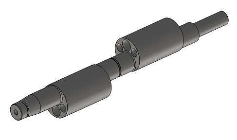
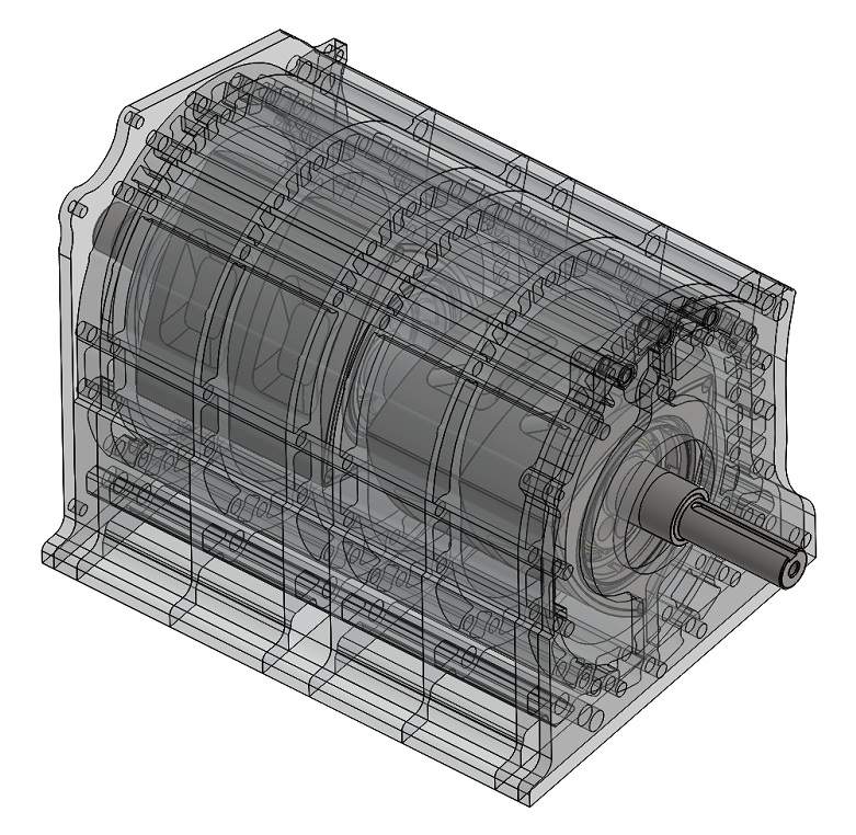
- The stock e-shaft obviously wouldn't work, for one the shaft is too short, and for two the shaft isn't made for the added weight. So a custom 2-piece e-shaft with a supporting bearing in the intermediate housing is in order. I've got the following design in mind:
- There needs to be a seal between the two stacked rotor housings. This can be solved to machine o-ring grooves in one housing like the older <86 housings had
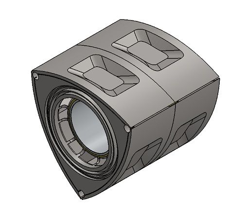
- 2 Rotors need to be modified and joined together. I think the best way to do this is machine the parts of the rotors that are going to be joined, and then turn two inserts, and some dummy cornerseals to support the apex-seals. Then weld the rotors in some non-critical area's away from the seal grooves. It would look something like this:
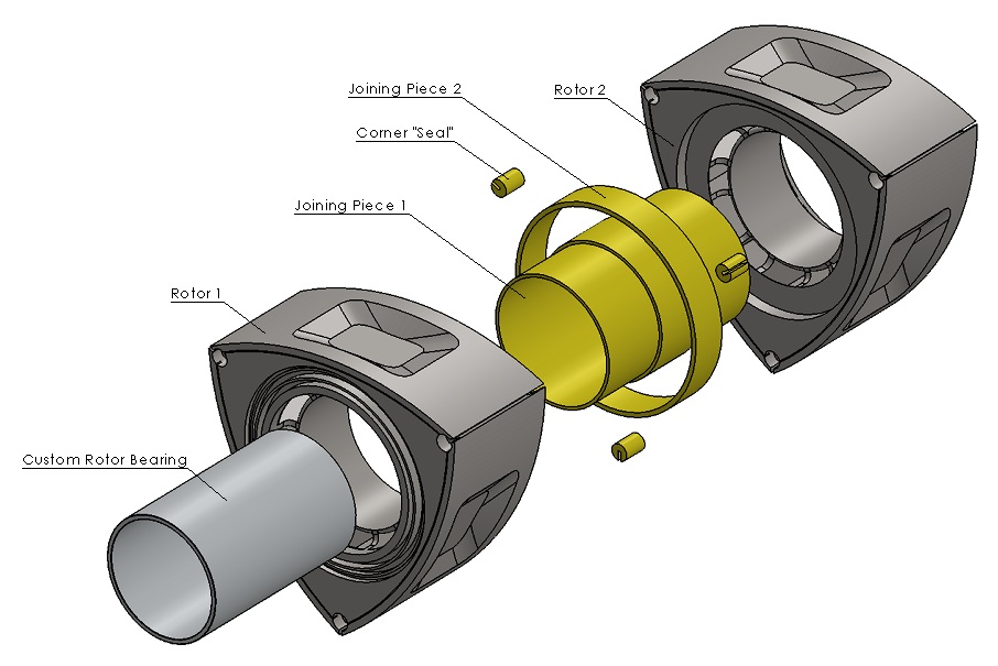
I guess the weight of these rotors will be around 8kg's.
- Obviously there are a LOT of other custom thing's that have to be made, custom exhaust manifold, custom oilpan, custom intake manifold, custom counterweights.
The whole goal of this is obviously to create an engine with a lot of torque and power, without the disadvantages such as turbolag and bad streetability. Yes it's a lot of work, but I don't think it's more work than building a 4rotor engine, and I can turn, mill or modify almost all of the parts myself. I also have 2 low milage S2 N/A engines in good shape lying around.
But my question, anyone ever thought about this? I've never seen anything like it, so there must be a reason for that.
I've been thinking about it for a while, and there are obviously a lot of problems with this, but the more I think about it, the more I think it can be done. Some of the problems:
- The stock e-shaft obviously wouldn't work, for one the shaft is too short, and for two the shaft isn't made for the added weight. So a custom 2-piece e-shaft with a supporting bearing in the intermediate housing is in order. I've got the following design in mind:
- There needs to be a seal between the two stacked rotor housings. This can be solved to machine o-ring grooves in one housing like the older <86 housings had
- 2 Rotors need to be modified and joined together. I think the best way to do this is machine the parts of the rotors that are going to be joined, and then turn two inserts, and some dummy cornerseals to support the apex-seals. Then weld the rotors in some non-critical area's away from the seal grooves. It would look something like this:
I guess the weight of these rotors will be around 8kg's.
- Obviously there are a LOT of other custom thing's that have to be made, custom exhaust manifold, custom oilpan, custom intake manifold, custom counterweights.
The whole goal of this is obviously to create an engine with a lot of torque and power, without the disadvantages such as turbolag and bad streetability. Yes it's a lot of work, but I don't think it's more work than building a 4rotor engine, and I can turn, mill or modify almost all of the parts myself. I also have 2 low milage S2 N/A engines in good shape lying around.
But my question, anyone ever thought about this? I've never seen anything like it, so there must be a reason for that.
Joined: May 2005
Posts: 2,745
Likes: 0
From: North Bay, Ontario
I believe you could physically get it to work, but the biggest problem IMO would be the width of the combustion chamber. It seems like it would be difficult to efficiently fill the entire combustion chamber in a uniform mixture using sideports, especially at higher RPM's. Peripheral ports would probably help, but there's also the issue of having two separate combustion chambers within the housing itself, and how the two flame fronts will interact. Not to mention, Mazda went with a taller rotor chamber for the 16x mainly because it made for a more efficient design, more like the 12A. This would be doing the opposite, to quite an extreme. Not saying Mazda is always right, but I'm sure there was sound reasoning for this.
My question would be, if you were going through the trouble of having a custom e-shaft machined, do you not feel you'd be better off simply going with a "natural" high-compression 4-rotor with individual combustion chambers, or even a 3-rotor?
Now, if you took 10A rotors on the other hand (60mm in width vs 70mm on the 12A or 80mm on the 13B) you would get a combined width of 120mm, and therefore would be adding 50% more width vs 100% more of the 13B. You might even accomplish this by modifying both rotor combustion chambers by grinding away the inside faces of each rotor, creating one uniform combustion chamber, and afterwards filling it in to reach a desired compression ratio. This would be a lot of work however, and I don't even know where to find 10A rotors, it's just food for thought...
Edit: I just re-read my post, and wanted to clarify. I'm not trying to put your idea down one bit, you've obviously put a lot of thought and effort into the modeling and design, and I think it's awesome that individuals are still trying to push technology forward for the rotary! I'm just trying to offer some insight from another perspective, and in the end I hope you go through with it and find out for sure if it will work.

Joined: Mar 2001
Posts: 31,857
Likes: 3,243
From: https://www2.mazda.com/en/100th/
ive had the idea, but didn't go as far as to model it!
joining rotor housings is/are easy, as you can use water seals. joining rotors is the trick, i wonder if using an extra deep side seal/corner seal would work well enough? welding wont work, as you have to be able to assemble/disassemble it. or maybe a solid piece where the rotor oil seals go?
joining rotor housings is/are easy, as you can use water seals. joining rotors is the trick, i wonder if using an extra deep side seal/corner seal would work well enough? welding wont work, as you have to be able to assemble/disassemble it. or maybe a solid piece where the rotor oil seals go?
Thread Starter
Joined: Oct 2010
Posts: 605
Likes: 13
From: The Netherlands
I believe you could physically get it to work, but the biggest problem IMO would be the width of the combustion chamber. It seems like it would be difficult to efficiently fill the entire combustion chamber in a uniform mixture using sideports, especially at higher RPM's. Peripheral ports would probably help, but there's also the issue of having two separate combustion chambers within the housing itself, and how the two flame fronts will interact. Not to mention, Mazda went with a taller rotor chamber for the 16x mainly because it made for a more efficient design, more like the 12A. This would be doing the opposite, to quite an extreme. Not saying Mazda is always right, but I'm sure there was sound reasoning for this.
My question would be, if you were going through the trouble of having a custom e-shaft machined, do you not feel you'd be better off simply going with a "natural" high-compression 4-rotor with individual combustion chambers, or even a 3-rotor?
Now, if you took 10A rotors on the other hand (60mm in width vs 70mm on the 12A or 80mm on the 13B) you would get a combined width of 120mm, and therefore would be adding 50% more width vs 100% more of the 13B. You might even accomplish this by modifying both rotor combustion chambers by grinding away the inside faces of each rotor, creating one uniform combustion chamber, and afterwards filling it in to reach a desired compression ratio. This would be a lot of work however, and I don't even know where to find 10A rotors, it's just food for thought...
Edit: I just re-read my post, and wanted to clarify. I'm not trying to put your idea down one bit, you've obviously put a lot of thought and effort into the modeling and design, and I think it's awesome that individuals are still trying to push technology forward for the rotary! I'm just trying to offer some insight from another perspective, and in the end I hope you go through with it and find out for sure if it will work.
My question would be, if you were going through the trouble of having a custom e-shaft machined, do you not feel you'd be better off simply going with a "natural" high-compression 4-rotor with individual combustion chambers, or even a 3-rotor?
Now, if you took 10A rotors on the other hand (60mm in width vs 70mm on the 12A or 80mm on the 13B) you would get a combined width of 120mm, and therefore would be adding 50% more width vs 100% more of the 13B. You might even accomplish this by modifying both rotor combustion chambers by grinding away the inside faces of each rotor, creating one uniform combustion chamber, and afterwards filling it in to reach a desired compression ratio. This would be a lot of work however, and I don't even know where to find 10A rotors, it's just food for thought...
Edit: I just re-read my post, and wanted to clarify. I'm not trying to put your idea down one bit, you've obviously put a lot of thought and effort into the modeling and design, and I think it's awesome that individuals are still trying to push technology forward for the rotary! I'm just trying to offer some insight from another perspective, and in the end I hope you go through with it and find out for sure if it will work.
ive had the idea, but didn't go as far as to model it!
joining rotor housings is/are easy, as you can use water seals. joining rotors is the trick, i wonder if using an extra deep side seal/corner seal would work well enough? welding wont work, as you have to be able to assemble/disassemble it. or maybe a solid piece where the rotor oil seals go?
joining rotor housings is/are easy, as you can use water seals. joining rotors is the trick, i wonder if using an extra deep side seal/corner seal would work well enough? welding wont work, as you have to be able to assemble/disassemble it. or maybe a solid piece where the rotor oil seals go?
talking head
Joined: Apr 2008
Posts: 2,775
Likes: 15
From: Perth, WA, OZ
http://www.ausrotary.com/viewtopic.php?f=3&t=207806
we are all still trying to work out if this one is a scam,, or if it actually happened,, or not
-----------------
that dual chamber is being fed only from the side ports that normally feed one engine,, not two
the equiv of feeding two cylinders,, but with one set of inlet valves?
i would think you would need to go PP to take advantage out of the extra displacement without choking it to the runners and intake of the standard 12a/13b
Thread Starter
Joined: Oct 2010
Posts: 605
Likes: 13
From: The Netherlands
Yes, I saw that 2B thing a while ago.
I agree that the side ports will be too small for the engine. That's why I want to make the best out of it, by porting the side housings as large as possible (while retaining the stock port timings), and turbocharging it.
I'm not trying to make an engine with double the horsepower of a 13B here, I'm trying to make an engine with a lot of torque and driveability. The fact that the ports are small for the displacement will definitly help in this department.
Two peripheral ports would make the most power, but driveability goes out the window. Maybe two very small p-ports. Engine life is also an important factor here, I don't want to spend half a year building an engine which only last a few thousand miles.
Trending Topics
You know I was Bs'ing about this same concept years ago.
https://www.rx7club.com/showthread.p...=double&page=4
I guess someone actually decided to go ahead and make it after all these years. LOL!
https://www.rx7club.com/showthread.p...=double&page=4
I guess someone actually decided to go ahead and make it after all these years. LOL!
Senior Member


Joined: Jul 2007
Posts: 432
Likes: 14
From: california/n. carolina
Not thinking too in depth and prolly might be a lil too much but what about custom housings and rotors that arnt just welded together but are already created as one unit- two long housings and 2 long rotors with only 3 compression grooves instead of 6? This might not even make sense lol just a thought...
tard of teh century
Joined: Jul 2005
Posts: 104
Likes: 1
From: Dublin, OH
You could always try blocking off runners on a regular 13B and see how it turns out for your power curve. This would give you a bit of an idea of how much you're going to choke the top end if you effectively only have one port per rotor. Hopefully you'll get the project figured out as it would be awesome to see.
I don't really see this as being easier than a normal four rotor though. You're still making a custom e-shaft so that's the same. Still need a custom exhaust and intake, so that's the same. Still need an aftermarket ECU to control them but if you're going for a far less power goal than you maybe able to get away with less/smaller injectors. Also if you're also planning on some way of casting into the plates I don't see why you would be against adding stationary gears. Both are going to require a good bit of work and the heat from casting will require you to remachine the plates as I don't see them making a good fit and seal without warping anything. I think you're basically just sacrificing efficiency for weight, as you'll have less plates.
I don't really see this as being easier than a normal four rotor though. You're still making a custom e-shaft so that's the same. Still need a custom exhaust and intake, so that's the same. Still need an aftermarket ECU to control them but if you're going for a far less power goal than you maybe able to get away with less/smaller injectors. Also if you're also planning on some way of casting into the plates I don't see why you would be against adding stationary gears. Both are going to require a good bit of work and the heat from casting will require you to remachine the plates as I don't see them making a good fit and seal without warping anything. I think you're basically just sacrificing efficiency for weight, as you'll have less plates.
Thread Starter
Joined: Oct 2010
Posts: 605
Likes: 13
From: The Netherlands
Not thinking too in depth and prolly might be a lil too much but what about custom housings and rotors that arnt just welded together but are already created as one unit- two long housings and 2 long rotors with only 3 compression grooves instead of 6? This might not even make sense lol just a thought...
Anyway, I've done a lot of work in CAD, and I think I'm going ahead with the project for now. I am going to wait with modifying the rotors and rotor housings, because well there's a fair chance that this project get's aborted for some reason, and I don't want to be stuck with 4 unusable rotors and 2 unusable rotor housings. I'm going to try to fabricate the e-shaft first, because it's one of the most difficult parts of the project, and if the project gets aborted all I've wasted is time and some material.
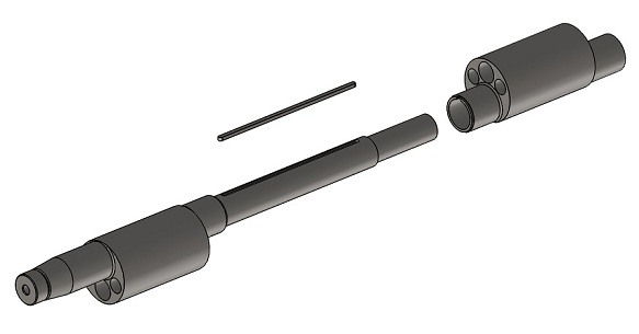
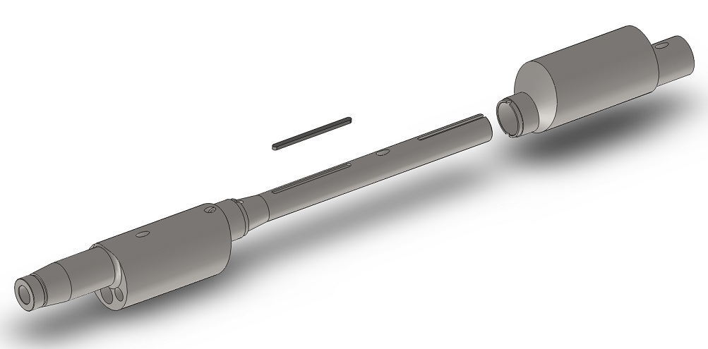
I already had made a quick drawing of the construction, but I've drew up a shaft with all of the exact sizes and details for manufacturing. I've also got a bit of forged crankshaft material (34CrNiMo6+QT), not enough for the entire shaft, but enough to get started with the slip-on piece. Anyway, here is the design:
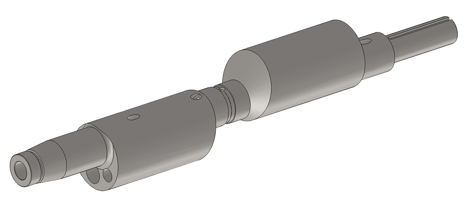
Note the conical piece where the slip-on piece sits on, this is to lock the slipon piece. All two piece shafts (20B, 26B, Guru shaft) have this so it must be a good idea.
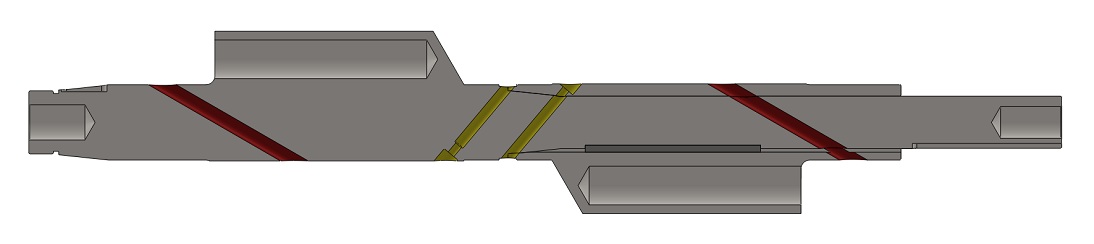
And here is a cutout view. Note that there isn't any central hole in the shaft, just a hole for the pilot bearing and a threaded hole for the front bolt. I did this for two reasons, for one the central hole weakens the shaft, not somuch when you think of torque, but more when you think of bending forces). The second reason is that I can't drill such a long hole on my lathe, I probably can't get the drill to stay aligned. The shaft is 23 inches long. Besides, this doesn't add a lot of inertia because the mass is centered.
Instead of the central hole I'm going to use crossdrilled holes for lubrication. The yellow coloured holes are going to supply oil for the jets (I'm planning on using mikuni #220 main jets) These are fed by holes through the bearing in the intermediate housing. The red coloured holes supply oil for the rotor bearings. These are fed through the main bearings. This means that all three engine bearings have got to have it's own oil supply, this is done by adding a adapter underneath the oilfilter and placing looplines.
You could always try blocking off runners on a regular 13B and see how it turns out for your power curve. This would give you a bit of an idea of how much you're going to choke the top end if you effectively only have one port per rotor. Hopefully you'll get the project figured out as it would be awesome to see.
I don't really see this as being easier than a normal four rotor though. You're still making a custom e-shaft so that's the same. Still need a custom exhaust and intake, so that's the same. Still need an aftermarket ECU to control them but if you're going for a far less power goal than you maybe able to get away with less/smaller injectors. Also if you're also planning on some way of casting into the plates I don't see why you would be against adding stationary gears. Both are going to require a good bit of work and the heat from casting will require you to remachine the plates as I don't see them making a good fit and seal without warping anything. I think you're basically just sacrificing efficiency for weight, as you'll have less plates.
I don't really see this as being easier than a normal four rotor though. You're still making a custom e-shaft so that's the same. Still need a custom exhaust and intake, so that's the same. Still need an aftermarket ECU to control them but if you're going for a far less power goal than you maybe able to get away with less/smaller injectors. Also if you're also planning on some way of casting into the plates I don't see why you would be against adding stationary gears. Both are going to require a good bit of work and the heat from casting will require you to remachine the plates as I don't see them making a good fit and seal without warping anything. I think you're basically just sacrificing efficiency for weight, as you'll have less plates.
If I cast material into the housing I'll probably cast aluminium. This is a softer material than the iron housing, and has a lower melting temperature so I don't think it will warp the housing. It does have a different expansion rate, maybe use some defcon in the runner to make sure there won't be any water leaks. I'll have to look into this some more.
I'm not with you on the sacrificing efficiency for weight though, maybe in terms of power, but I bet a large displacement side port fed engine has far better mileage than a peripheral port 4rotor.
Last edited by John Huijben; Jul 31, 2011 at 05:52 PM.
Joined: Mar 2001
Posts: 31,857
Likes: 3,243
From: https://www2.mazda.com/en/100th/
Fair points, I have thought a lot about a 4rotor, but that kind of engine just isn't streetable. Wicked as hell though.
I'm not with you on the sacrificing efficiency for weight though, maybe in terms of power, but I bet a large displacement side port fed engine has far better mileage than a peripheral port 4rotor.
I'm not with you on the sacrificing efficiency for weight though, maybe in terms of power, but I bet a large displacement side port fed engine has far better mileage than a peripheral port 4rotor.
2. peripheral ports do have some issues in a street application, but with EFI its really close to a side port. the issues basically are noise, and sensitivity to back pressure. Mazda's 4 rotor engines are race engines only, if you go see the 787B run, it actually acts a lot like a stock FC. if you built the engine with an eye toward street use it might be quite nice.
mileage? yes, putting around the side port should be a little better, the P port has better bsfc, but it still uses more fuel because it makes more power.
not to dissuade you from your project, do it! it'll be interesting
Joined: May 2005
Posts: 2,745
Likes: 0
From: North Bay, Ontario
Just a couple arguments re: the natural 4-rotor.
1) Engine management: Can be exactly the same as your design, if you design the e-shaft to fire 1-3 together and 2-4 together (180* offsets) vs a 90* rotor offset.
2) You don't have to go full P-Port on a 4-rotor. I was just discussing this with another guy looking to go side-port 4-rotor. If you used all standard intermediate housings, and just modified the front and rear iron to have smaller ports, each rotor would have 2 primary ports feeding it. This would be no less efficient than having 1 large port per rotor with your design IMO, even though it won't be nearly as efficient as a PP.
3) Stationary gears: I don't have any exp. here, but it seems to me that it would not be much if any more difficult to machine stationary gears for the int. housings than modifying a center iron for a bearing in your current design. It would also give the rotors better support; with your configuration you will be essentially doubling the load on the stationary gear teeth.
3) Exhaust: Someone covered that, same difficulty.
4) Cooling: I suspect you may have the same issues as a 4-rotor keeping the second "stacked" rotor housing of each pair cool, especially if it's being fed hot coolant from the front chamber.
5) "porting the side housings as large as possible" and "retaining the stock port timings" Just doesn't work. The only way to increase area without affecting timing is to port towards the oil seal (very limited distance) and to port the bottom of the port about as large as a cosmo port. And once you have two large ports feeding the large combustion chamber, low-end torque (which you seem to be seeking) will very likely be negatively affected vs. having a small primary port and large secondary for each.
6) Engine life: Time will tell for this design, but I still feel that the cooling challenges with this configuration could negatively impact engine life.
7) Oil supply: With your configuration, it looks like you will be more than doubling the surface area of the rotor bearings, while keeping supply roughly the same as stock. This may or may not be an issue. I might suggest that you cross drill the shaft twice, once on each side of the stationary gear lobe of the e-shaft to increase your supply. If you slightly offset them, you could keep them both independent.
Also, it doesn't look like the outside rotor of each pair will not be receiving the cooling of the oil jets (and oil cooling accounts for 1/3 of total engine cooling in a rotary)
About the casting in the runners, if you read up some posts by Lynn Hanover from nopistons.com, he recommends using the Devcon putty, and then drilling and tapping through it into the existing housing and using a set-screw to make sure it doesn't come loose and destroy your engine.
In the end, I just really want to see another true 4-rotor project, which is why I'm being argumentative. LOL
Thread Starter
Joined: Oct 2010
Posts: 605
Likes: 13
From: The Netherlands
Nothing wrong with people being argumentative, it's why I started this thread in the first place 
There are actually a few good arguments there, dammit.
When I think about it again, a non turbo 4rotor is actually about the same amount of work than this 2+2 design, especially if it needs turbocharging to get enough air into the engine. Plus it has been done already so I know it works, and it's a lot cooler.
I just can't picture a peripheral ported 4rotor as a daily driver though. Maybe a smaller wider port cut high in the housing to reduce overlap Lot's of food for thought here.
There are actually a few good arguments there, dammit.
When I think about it again, a non turbo 4rotor is actually about the same amount of work than this 2+2 design, especially if it needs turbocharging to get enough air into the engine. Plus it has been done already so I know it works, and it's a lot cooler.
I just can't picture a peripheral ported 4rotor as a daily driver though. Maybe a smaller wider port cut high in the housing to reduce overlap
Lot's of food for thought here.
Joined: Mar 2001
Posts: 31,857
Likes: 3,243
From: https://www2.mazda.com/en/100th/
Joined: Mar 2001
Posts: 31,857
Likes: 3,243
From: https://www2.mazda.com/en/100th/
i'm not looking at the picture, but i think the cold water inlet on a mazda 4 rotor is on the center, so its like cooling 2 13b's
tard of teh century
Joined: Jul 2005
Posts: 104
Likes: 1
From: Dublin, OH
You could always look into running a semi-pp. Seems like they come back into the spotlight every few years but the 20b that was around recently is the only one I remember running it closed off at the beginning. If it does turn out that you aren't getting the airflow you're wanting you could put a couple of short but wide peripheral ports and throttle them as the 20b did. Seemed like the best of both worlds but it's hard to say when there's so few people pulling it off. Would definitely add even more uniqueness to your project.
Can you really be that worried about fuel economy when you're doubling the displacement of your motor?
Here is the thread with that 20b
https://www.rx7club.com/20b-forum-95/defined-n-20b-semi-p-port-421rwhp-931068/
Can you really be that worried about fuel economy when you're doubling the displacement of your motor?
Here is the thread with that 20b
https://www.rx7club.com/20b-forum-95/defined-n-20b-semi-p-port-421rwhp-931068/
just to add my two cents ....
i'd be quite worried about a 160 mm long apex seal in a combustion environment. generally speaking, i, too, don't see it being any less of an issue building this engine as opposed to building a 26B. you still have to fabricate a shaft, modify housings and use custom tension bolts - but you're also adding customized rotors to the work (fabrication) load. however, i do see the monstrous torque advantage to this method though. personally, i like the idea and if you can make it happen, i say go for it.
if Madbouncy didn't say it already, i definitely would have been the first to say consider semi-peripherals to augment the modified sideports. you wouldn't have to make anything nearly as complicated as the intake system on the Renesis, but if you make a system similar to Toyota's TVIS, i think it would create quite a driveable setup.
Joined: Mar 2001
Posts: 31,857
Likes: 3,243
From: https://www2.mazda.com/en/100th/
here's an idea. it might not be possible, but why not cut the rotor apart and section it? and instead of going 160mm wide, maybe you only 120mm? that gives you 10A dimensions. either cut a rotor in half, and use 2 halves, or cut the center, and use an insert.
rotor housings could be milled down rx8, you put your own exhaust port in it.
rotor housings could be milled down rx8, you put your own exhaust port in it.
Thread Starter
Joined: Oct 2010
Posts: 605
Likes: 13
From: The Netherlands
That would be crazy difficult to fabricate, and you'll get a very low compression ratio because instead of 2 small original bowls, you get one large bowl, with less displacement.
I've also thought of this, but you seem to be way more ahead and equipped to do it!!
I've also thought about, the opposite direction..
to make custom rotors/housings only 40 mm wide.... and to use 4 to 6 of them. 1.3 to 1.8. other wise the same stock detentions. just thoughts... the rotors could NOT be cut in half, they would have to be custom made.. but should result in more power for the same displacement (4 rotor version).

Junior Member
Joined: Jul 2008
Posts: 10
Likes: 0
From: Rochester NY
http://www.rotaryeng.net/pat20090101103.pdf
According to this paper it is a really bad idea to do what you propose as Wankel engines prefer high L/b ratios for every aspect of performance.
According to this paper it is a really bad idea to do what you propose as Wankel engines prefer high L/b ratios for every aspect of performance.
^ interesting paper.
Also, visualizing your design using two stock rotors fused together vs two half-cuts made into one larger rotor, it would seem that the division in between the two bathtubs would provide a major impediment to both charge flow and flame front propogation, as it is a small gap and would provide poor flow and large quenching area...
Also, visualizing your design using two stock rotors fused together vs two half-cuts made into one larger rotor, it would seem that the division in between the two bathtubs would provide a major impediment to both charge flow and flame front propogation, as it is a small gap and would provide poor flow and large quenching area...
Thread Starter
Joined: Oct 2010
Posts: 605
Likes: 13
From: The Netherlands
Yes, all true, it wouldn't be the most effici�nt engine. I ditched the idea anyway, I'm building a 4-rotor now. Rotor housings are done, E-shaft is also coming along great. Also lot's of work, but should be great when done.
