
Power FC settings 5 custom features? datalogit

settings 5 custom features? datalogit
In settings 5 i noticed in the lower left hand corner some special features with check boxes.
FC Box Custom Features (Key Off / Key On for changes to take effect)
[__________] Tuner string (8 char)
[]ENABLED
[]Boost switch (SW4/AN8)
[]AN5-8 Switch to ground (Internal 5v pullups)*
*This option allows simple wiring and logging of switches(good for Boost Switch Feature) but reduces AN5-8 input accuracy. Only use if all AN5-8 are switch inputs.
What does this stuff do? It sounds like you can enable it to use the AN5-8 as switches. I'm wondering if I could use this to activate my water injection solenoid rather then my boost sensor switch.. or if these serve a different purpose?? How can they be used? Do they only work if the laptop is connected or does it somehow activate something in the datalogit??
Ok did more research and I guess the boost switch is just for switching between settings 1 and 2. You can switch between boost settings with a momentary switch wired from ground to the datalogit sw4/AN8. (Something like that anyway... I already have one wired up to my profec B for low/high so didn't pay full attention on how it gets wired up.)
The AN5-8 Switch to ground. I'm still not exactly sure what this does but I don't think its useful for much more then simplifying the boost switch in some way.
It would be nice to be able to activate things using the datalogit, but I cant think of any other ways these settings could be used. I tried to think if any of the crap I disconnected when going single could some how control additional features by using them to activate relays, but so far can't think of a good way to make use of that stuff.
EDIT: Just had an idea... what if the seq turbo control check box was checked, and then the turbo control solenoid harness' were connected to relays to be used as RPM switches. Changing the turbo transition RPM numbers would change the point at which they were activated. And putting in 100% duty should keep the signal from going on/off on/off. I don't know if this would work very well or at all, just something I thought of. Anyone have any ideas?

100ms would work fine. User programmable boost and rpm would be nice. Those are the primary ones. Water temp might be useful for some but i wouldn't worry about that one if it takes awhile to add these kind of things.


Just had an idea... what if the seq turbo control check box was checked, and then the turbo control solenoid harness' were connected to relays to be used as RPM switches. Changing the turbo transition RPM numbers would change the point at which they were activated. And putting in 100% duty should keep the signal from going on/off on/off. I don't know if this would work very well or at all, just something I thought of. Anyone have any ideas?
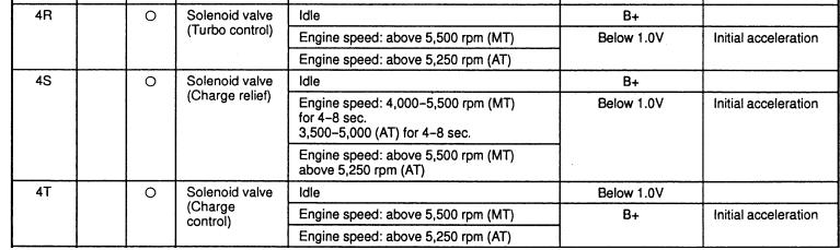
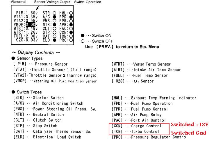
What you need to do is enable sequential turbo control. Set all 3 of your "High" transition values to whatever target RPM you are looking for. Under the monitor window, click "switches" and then click TCN and and CCN. Then wire in an LED or some other such diagnostic method to each output for diagnostic purposes. The LED for the TCN should be run to power, and then the ground would be switched by the PFC at the target RPM. The LED for the CCN would be grounded, and then the +12V would come from the PFC.
Go out and drive the car. See if the LED's light up. Verify the control behavior of the PFC through the log (see if the TCN is being switched at exactly the transition value you input under the transition settings). I'm not sure how an active switch comes up in the Log Viewer program of FC-Edit, but there should at least be something you can find in the .txt file if you open it with Excel. Post that log up.
Trending Topics
Thanks for the information, I think it will work. Could be used as an rpm switch at the very least if it works out as planned. Are the charge control and turbo control activated at different RPMs? If so, it might be possible to run RPM stages for certain things.
For relay switching purposes only one of them would have to be used, either the ground or 12v+ because the rest of the circuit could be completed either on the frame, the battery, or an aux switch. I think the connections at the harness already have both + & ground, so extra wires probably wouldn't need to be run.
I'll try to do some testing with a multimeter when I have the ambition to figure out which wires used to go to the charge control and turbo control solenoids. One of these days I need to simplify the whole harness too... or get another one and simplify it..
In this pic, https://www.rx7club.com/attachment.p...6&d=1240870897
I think the turbo control may be the silver rats nest plug, 3rd from the left. I am basing that on the stock vacuum routing diagram, http://www.rx7.org/Robinette/images/hoses.gif , solenoid letter "E"
From the factory they appear to be switched at the same time.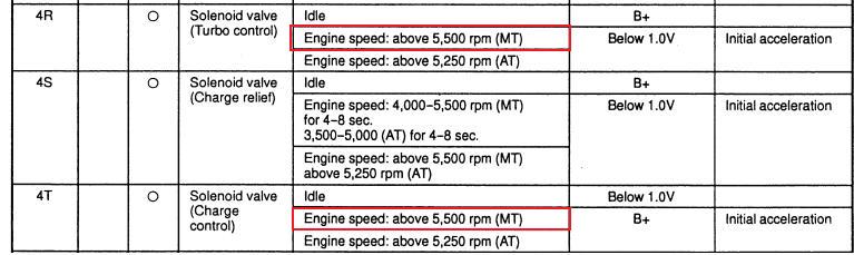
A datalog and the LED test I mentioned would confirm this. If you are testing with an LED, just locate pin 4R and strip back part of the wire under the dash, then hook up an LED from there. Or just use a ghetto vampire tap. You also could take a multimeter lead, backprobe the pin on one end of the lead, then strip the other end of the lead and twist it on to the ground side of the LED.

Thread
Thread Starter
Forum
Replies
Last Post
Jeff20B
1st Generation Specific (1979-1985)
4
Jun 26, 2016 10:21 AM