
Power FC Replacement Mini DIN cable for Dartalogit?

Replacement Mini DIN cable for Dartalogit?
Loaned out my Datlogit a while back and when it was returned - someone broke the guide pin out of the mini din plug and bent a few pins.
I cut the end of the cable figuring I could pull a fast one and just solder a PS2 connector from an old keyboard or mouse in. NOPE! Its not the same.
Opened up the datalogit and here are the connections:
RED
PURPLE
YELLOW
BLACK
WHITE
Shielding
Where can I get a replacement cable to solder in?
I cut the end of the cable figuring I could pull a fast one and just solder a PS2 connector from an old keyboard or mouse in. NOPE! Its not the same.
Opened up the datalogit and here are the connections:
RED
PURPLE
YELLOW
BLACK
WHITE
Shielding
Where can I get a replacement cable to solder in?
Joined: Dec 2001
Posts: 10,630
Likes: 3
From: NY, MA, MI, OR, TX, and now LA or AZ!
I'm lost here.... What are you trying to fix? The entire cable or just the connector?
If you just need the connector:
MD-50 Mini-Din 5
I use those for all of my PowerFC adapter boxes.
If you just need the connector:
MD-50 Mini-Din 5
I use those for all of my PowerFC adapter boxes.
I would fix either - but I cut the connector off and tossed it in the trash figuring that any PS2 connector would wire right in.
It might have worked except the color codes are different and I didn't pin out the connector before I trashed it.
What I really need is for someone to take pity on my ***-hattery and pin out the datalogit connector to the cable color for color. This way I can add a new connector or cable or whatever.
Joined: Dec 2001
Posts: 10,630
Likes: 3
From: NY, MA, MI, OR, TX, and now LA or AZ!
I meant on the PCB itself -- not the connector.
You should have:
1 - GND
1 - 5V
1 - 12V (probably not connected to anything)
1 - RX (this will be hard to find with a MM)
1 - TX (this too will be hard to find with a MM)
The ground should be easy to track down, as should the 5V and 12V. This leaves you the two communication lines, that you may have to trace on the board to determine which is which. Definitely, it'll be easier for someone to pin it out for you, but if you can't find that...
Trending Topics
Years ago when mine actually went bad due to internal wire breakage, I could not find any 5 pin DIN on the web. I used a 6 pin, broke off the alignment plastic tab, and removed the sixth pin.
So simple a cave man can do it.
So simple a cave man can do it.
Junior Member
Joined: Jul 2014
Posts: 25
Likes: 0
From: tx
I think this is what your looking for.
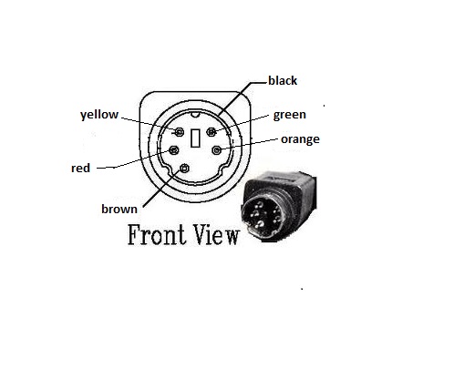
This is how my commander pins out. It is a non oled.
and on the black and red wires I got continuity through both wires at both pins. I made the assumption that the largest of the wires (black) goes to the outer shield. But I could be wrong and the red and black could be swapped.
This is how my commander pins out. It is a non oled.
and on the black and red wires I got continuity through both wires at both pins. I made the assumption that the largest of the wires (black) goes to the outer shield. But I could be wrong and the red and black could be swapped.

New to the Club!
Joined: Dec 2020
Posts: 1
Likes: 0
From: QLD
Hey Guys,
Sorry to redig this post from the dead, but I have a similar problem.
Got my car back from the tuners and they broke the plug from my Datalogit to the ECU.
I cut the plug off but cant piece together what colour is what, any my colours are very different to those in the diagram above. I have the black box Datalogit and the colours I see in the cable are as follows:
1. Cable shielding wire.
2. Black.
3. Red.
4. Green.
5. Blue.
6. Brown.
7. White.
Please help!

Thread
Thread Starter
Forum
Replies
Last Post
ZaqAtaq
New Member RX-7 Technical
2
Sep 5, 2015 08:57 PM
Nosferatu
2nd Generation Specific (1986-1992)
7
Sep 5, 2015 02:13 PM