
Power FC New Power FC Software RasPexi Viewer


That dropbox link doesn't work for me. I downloaded your image from your google drive link in post # 232. Unzipped it and wrote it to my SD card last night but didn't get around to powering it up yet. Plus I need to figure out where to mount my 10" LCD screen in the car... Could get interesting
Thread Starter
Senior Member
Joined: Aug 2013
Posts: 613
Likes: 44
From: Wolnzach Germany
I made quickly a new image this morning and uploaded it . You need a 8GB card for this
https://drive.google.com/open?id=0Bw...mtIWnl2VTUxYXM
it will autostart into Raspexi at boot .
when using in the first time , quit raspexi by pressing "Q" on the keyboard .
Then type the following :
startx
When the desktop has started go the the start menu and open the raspiconfig.
select "expand filesystem" then reboot
Thread Starter
Senior Member
Joined: Aug 2013
Posts: 613
Likes: 44
From: Wolnzach Germany
Hi Guys
I finally managed to adapt the megatunix dash dedsigner to raspexi and add the raspexi datasources . I made a new image with working dash designer and uploaded it to my google drive .Happy dash designing
https://drive.google.com/open?id=0Bw...FU2RHNKdl90WTg
I finally managed to adapt the megatunix dash dedsigner to raspexi and add the raspexi datasources . I made a new image with working dash designer and uploaded it to my google drive .Happy dash designing
https://drive.google.com/open?id=0Bw...FU2RHNKdl90WTg


REVIT
Joined: Mar 2008
Posts: 130
Likes: 4
From: Florida
Raspexi
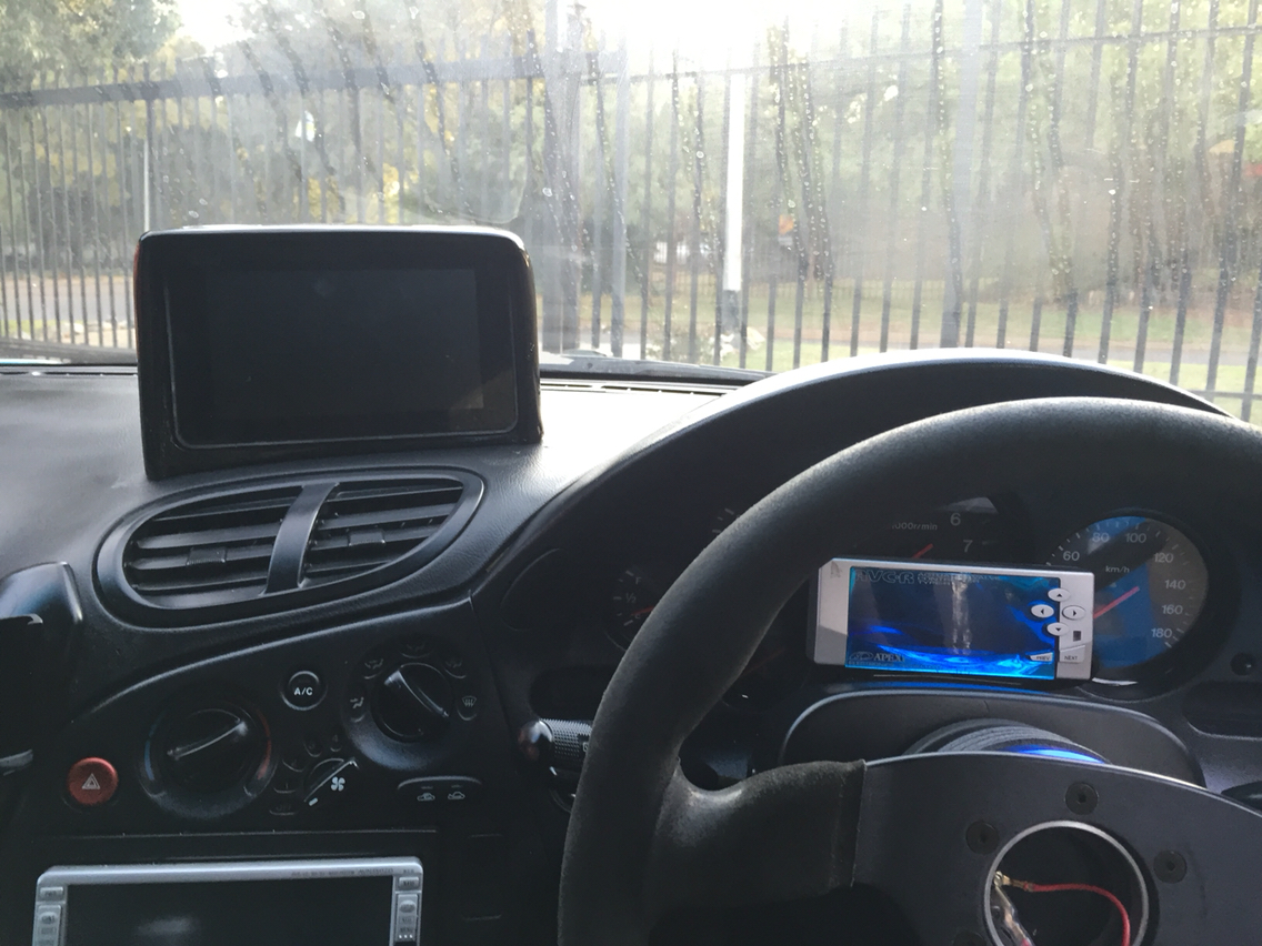
Hi Markus, so will all the components fit into that enclosure? What is the display that is depicted? Interesting to see it running in the car. Looks good and the carbon fiber looks good as well.
Thread Starter
Senior Member
Joined: Aug 2013
Posts: 613
Likes: 44
From: Wolnzach Germany
Originally Posted by REVIT93RX7
Hi Markus, so will all the components fit into that enclosure? What is the display that is depicted? Interesting to see it running in the car. Looks good and the carbon fiber looks good as well.
https://www.adafruit.com/product/2718
http://mausberry-circuits.myshopify....upply-switches
There is still plenty space for the cables and ventilation as well
Junior Member
Joined: Jun 2016
Posts: 4
Likes: 0
From: Birmingham, UK
I'm loving the look of this as a nice neat solution to get extra info out of the ECU!
I got an RPi 2 loaded up with the image last night and have just fitted a 2 DIN head unit to my FD last weekend so i'm working towards having everything, just saving up some cash to buy an FC Datalogit and i should be able to give it a try. I'm assuming everything will be fine for use on a '99 spec FD PowerFC as i can't see a reason the interface port would have changed much.
I've had a cursory look over the protocol for the early PowerFC interface port and it looks like it shouldn't be too hard to build an add-on board for the RPi with a micro-controller (at worst a small FPGA or CPLD) on it to take the place of the FC Datalogit and other interfaces (which aren't much more than a micro controller and some level shifting circuitry anyway).
Once I've got it all working and I've got my hands on a logic analyser (I've been looking for an excuse to buy a Saleae logic for ages) I'll start trying to reverse engineer the protocol a bit more. APEX PowerFC?????? gives some really good clues about how simple it should be (even if their circuit design is a bit of an odd one) but the protocol it uses isn't well documented and i'd definitely agree with them referring to It's relation to I2C as "Bimyo". I'll have a dig through the user manual for the NEC micro-controller they found at the heart of the PowerFC and see if that says anything useful otherwise it'll just be a case of capturing the traffic to and from the ECU and working back from there.
Thread Starter
Senior Member
Joined: Aug 2013
Posts: 613
Likes: 44
From: Wolnzach Germany
I forgot to answer your question . All FD's use the same communication protocol , there is no difference on the interface port protocol between the Series 6 ,7 and 8 . So it will definitly work on a 99 spec series 8. You can also maybe ask SonicRat here on the forum , he actually built his own Datalogit like cable and even sold a few . Maybe he can give you some tips so you don't have to start from scratch
Last edited by Markus1981; Jun 22, 2016 at 05:21 AM.
REVIT
Joined: Mar 2008
Posts: 130
Likes: 4
From: Florida
Rx7 pc
We do have another option, Markus has done great work on RasPexi. I built a PC based solution that integrates a PC in the car and uses the datalogit to communicate with the ECU. It utilizes a 7" touch screen installed within the dashboard. Currently it reads ECU parameters and saves them to a file with synched GPS data. All data is displayed in real-time so you can monitor the performance of the car. I have other features designed to be part of this system as well. RasPexi would work great for anyone especially with the new features he is adding, just wanted to make another option available.
 The system don't let me save !
Junior Member
Joined: Jun 2016
Posts: 4
Likes: 0
From: Birmingham, UK
From the information on Kashimas page it looks like anything with a USART or more generic synchronous serial peripheral is going to be able to implement the protocol as long as it runs slow enough. I calculate the clock speed of the data to be 25KHz (40us period) from the timing diagram which is really slow so you could even bit bang it out with really slow micro-controller if you really had to.
The information is just a bit hard to follow even if Google translate does a pretty serviceable job on it. But, it looks like the PowerFC itself is the bus master for the two wire serial interface which would sort of make sense but then raises the question of who initiates communication.
It would be odd for a slave device to do it but then i'm not super familiar with SBI, however it looks like that's what the CMD-REL-CMD sequence is for. The NEC user manual calls that the start of "Bus Release signal transfer" so that must be how the Slave device asks the bus Master to release the Bus so that it can transmit. Then the PowerFC is address 0x10 which is why that gets sent, then 0x40 is sent to request data from the PowerFC and finally 0x02 which i'm not quite sure what that it is if it's anything (i'm assuming that is the actual command to ask for data - do you have different commands for different data or do you just get it all and you discard what you're not interested in).
This next bit is where i'm still figuring it out (and it'd be much easier if i had a PowerFC on my bench with a logic analyser and working interface). But i'm assuming it does one of the following:
- the PowerFC then performs the bus release signal back to you and starts shifting data out onto the serial data line that you as the slave device have to just catch.
- the PowerFC then performs the bus release signal back to you then sends an address and command back followed by the data you want (if so what're they going to be).
I'm going to mull over it a bit more and see if i can think my way around this one.
I think i've managed to solve the mystery of some of Kashimas odd design points on his interface schematic. Referencing the the datasheet for the PIC he's using in his interface it looks like he's using a pretty configurable USART with tri-state bus buffers to either allow the micro-controller to talk via the RS232 port or to the ECU but then there are also GPIO lines connected to the SCK and SBO lines to the ECU.
It must be a combination of bit banging (with the bus buffers (74LS125) facing the ECU set to high-Z) on GPIO pins for the more esoteric bits of the SBI protocol (like the bus release signal) followed by using the USART in synchronous mode to just shift some data out via the bus buffers and then going back to bit banging other bits. Then when the data has been collected from the ECU (however that happens) the USART flips over into UART mode, the buffers are set to connect it to the RS232 line transceiver before the data gets blasted out to the host system.
I'm sorry for the wall of text and it being a bit of a dump of a train of thought but i've been writing it and thinking about the problem at the same time so as i've come up with ideas i've just been writing a bit more of this post.
I forgot to answer your question . All FD's use the same communication protocol , there is no difference on the interface port protocol between the Series 6 ,7 and 8 . So it will definitly work on a 99 spec series 8. You can also maybe ask SonicRat here on the forum , he actually built his own Datalogit like cable and even sold a few . Maybe he can give you some tips so you don't have to start from scratch
Thread Starter
Senior Member
Joined: Aug 2013
Posts: 613
Likes: 44
From: Wolnzach Germany
Sorry i forgot to give permissions to the user on the raspexi folder .
You can do that very easily yourself
open a terminal window and type :
sudo chown -R $user /home/pi/raspexi
this will change the directory ownership to you and allow you to edit all files in the directory raspexi and its sub folders
I see your username mr2powerfc , are you going to use this in a Toyota MR2 ?
If so please give me feedback if everything displays correctly
Thread Starter
Senior Member
Joined: Aug 2013
Posts: 613
Likes: 44
From: Wolnzach Germany
Yeah, so do i which why i'd like to do it. I'd also like to help out on the software side at some point because i had a thought about using bluetooth or some other low power radio for the Pi to communicate data from the ECU wirelessly to physical gauges or warning lights.
From the information on Kashimas page it looks like anything with a USART or more generic synchronous serial peripheral is going to be able to implement the protocol as long as it runs slow enough. I calculate the clock speed of the data to be 25KHz (40us period) from the timing diagram which is really slow so you could even bit bang it out with really slow micro-controller if you really had to.
The information is just a bit hard to follow even if Google translate does a pretty serviceable job on it. But, it looks like the PowerFC itself is the bus master for the two wire serial interface which would sort of make sense but then raises the question of who initiates communication.
It would be odd for a slave device to do it but then i'm not super familiar with SBI, however it looks like that's what the CMD-REL-CMD sequence is for. The NEC user manual calls that the start of "Bus Release signal transfer" so that must be how the Slave device asks the bus Master to release the Bus so that it can transmit. Then the PowerFC is address 0x10 which is why that gets sent, then 0x40 is sent to request data from the PowerFC and finally 0x02 which i'm not quite sure what that it is if it's anything (i'm assuming that is the actual command to ask for data - do you have different commands for different data or do you just get it all and you discard what you're not interested in).
This next bit is where i'm still figuring it out (and it'd be much easier if i had a PowerFC on my bench with a logic analyser and working interface). But i'm assuming it does one of the following:
I'm going to mull over it a bit more and see if i can think my way around this one.
I think i've managed to solve the mystery of some of Kashimas odd design points on his interface schematic. Referencing the the datasheet for the PIC he's using in his interface it looks like he's using a pretty configurable USART with tri-state bus buffers to either allow the micro-controller to talk via the RS232 port or to the ECU but then there are also GPIO lines connected to the SCK and SBO lines to the ECU.
It must be a combination of bit banging (with the bus buffers (74LS125) facing the ECU set to high-Z) on GPIO pins for the more esoteric bits of the SBI protocol (like the bus release signal) followed by using the USART in synchronous mode to just shift some data out via the bus buffers and then going back to bit banging other bits. Then when the data has been collected from the ECU (however that happens) the USART flips over into UART mode, the buffers are set to connect it to the RS232 line transceiver before the data gets blasted out to the host system.
I'm sorry for the wall of text and it being a bit of a dump of a train of thought but i've been writing it and thinking about the problem at the same time so as i've come up with ideas i've just been writing a bit more of this post.
Aaah fantastic, i thought that might be the case but i know the 8-bit and 16-bit harnesses aren't compatible and the '99 onwards PowerFCs aren't compatible with '93 spec cars (not sure if that's just a connection to the vehicle harness problem or if the ECU hardware is incompatible)
From the information on Kashimas page it looks like anything with a USART or more generic synchronous serial peripheral is going to be able to implement the protocol as long as it runs slow enough. I calculate the clock speed of the data to be 25KHz (40us period) from the timing diagram which is really slow so you could even bit bang it out with really slow micro-controller if you really had to.
The information is just a bit hard to follow even if Google translate does a pretty serviceable job on it. But, it looks like the PowerFC itself is the bus master for the two wire serial interface which would sort of make sense but then raises the question of who initiates communication.
It would be odd for a slave device to do it but then i'm not super familiar with SBI, however it looks like that's what the CMD-REL-CMD sequence is for. The NEC user manual calls that the start of "Bus Release signal transfer" so that must be how the Slave device asks the bus Master to release the Bus so that it can transmit. Then the PowerFC is address 0x10 which is why that gets sent, then 0x40 is sent to request data from the PowerFC and finally 0x02 which i'm not quite sure what that it is if it's anything (i'm assuming that is the actual command to ask for data - do you have different commands for different data or do you just get it all and you discard what you're not interested in).
This next bit is where i'm still figuring it out (and it'd be much easier if i had a PowerFC on my bench with a logic analyser and working interface). But i'm assuming it does one of the following:
- the PowerFC then performs the bus release signal back to you and starts shifting data out onto the serial data line that you as the slave device have to just catch.
- the PowerFC then performs the bus release signal back to you then sends an address and command back followed by the data you want (if so what're they going to be).
I'm going to mull over it a bit more and see if i can think my way around this one.
I think i've managed to solve the mystery of some of Kashimas odd design points on his interface schematic. Referencing the the datasheet for the PIC he's using in his interface it looks like he's using a pretty configurable USART with tri-state bus buffers to either allow the micro-controller to talk via the RS232 port or to the ECU but then there are also GPIO lines connected to the SCK and SBO lines to the ECU.
It must be a combination of bit banging (with the bus buffers (74LS125) facing the ECU set to high-Z) on GPIO pins for the more esoteric bits of the SBI protocol (like the bus release signal) followed by using the USART in synchronous mode to just shift some data out via the bus buffers and then going back to bit banging other bits. Then when the data has been collected from the ECU (however that happens) the USART flips over into UART mode, the buffers are set to connect it to the RS232 line transceiver before the data gets blasted out to the host system.
I'm sorry for the wall of text and it being a bit of a dump of a train of thought but i've been writing it and thinking about the problem at the same time so as i've come up with ideas i've just been writing a bit more of this post.
Aaah fantastic, i thought that might be the case but i know the 8-bit and 16-bit harnesses aren't compatible and the '99 onwards PowerFCs aren't compatible with '93 spec cars (not sure if that's just a connection to the vehicle harness problem or if the ECU hardware is incompatible)
I hope this helps a little.
If you want to contribute to the Raspexi code , give me your github name and i can add you to the repo
Junior Member
Joined: Jun 2016
Posts: 4
Likes: 0
From: Birmingham, UK
Kashimas page has lots of info , but his cable has a few differences to the Hako and Datalogit . Kashimas Cable is only 19K Baud , the Hako and Datalogit are capable of 56K Baud . Also Kashima uses even parity in his protocol , the Hako and datalogit run with no parity . The best english information of the protocol can be found in this thread https://www.rx7club.com/power-fc-for...alogit-147597/
I hope this helps a little.
If you want to contribute to the Raspexi code , give me your github name and i can add you to the repo
I hope this helps a little.
If you want to contribute to the Raspexi code , give me your github name and i can add you to the repo
I'm not too worried about the interface to host system side commnication, that's the super easy bit. It's just the on-the-wire protocol from the interface to the PowerFC i'm trying to make sure I understand.
My end goal once this works is to just open source the entire thing from PCB design and GERBER files to source code of the firmware needed for whatever processing system the interface uses.
I'll PM you my github username when i get a moment / have tidied up the account a bit as i do most of my version control via bit bucket these days.

Junior Member
Joined: Jun 2016
Posts: 10
Likes: 0
From: Miami
Hi! Yes is for a MR2 3sgte , it works fine speed and tach and some others
Nice work!
Thanks for your reply!
Nice work!
Thanks for your reply!
Hi
Sorry i forgot to give permissions to the user on the raspexi folder .
You can do that very easily yourself
open a terminal window and type :
sudo chown -R $user /home/pi/raspexi
this will change the directory ownership to you and allow you to edit all files in the directory raspexi and its sub folders
I see your username mr2powerfc , are you going to use this in a Toyota MR2 ?
If so please give me feedback if everything displays correctly
Junior Member
Joined: Jun 2016
Posts: 10
Likes: 0
From: Miami
Hi Markus I type: sudo chown -R $user /home/pi/raspexi
not working
Says:
chown: missing aperand after ' /home/pi/raspexi
try 'chown --help' for more information
Thanks
not working
Says:
chown: missing aperand after ' /home/pi/raspexi
try 'chown --help' for more information
Thanks
Rotary Enthusiast
Joined: Jan 2004
Posts: 782
Likes: 3
From: Sonoma, CA
I think you need to use $USER
I am not near my pi to check but I am pretty sure it needs to be capitalized... so you could try this:
sudo chown -R $USER /home/pi/raspexi
or even use the user directly and do this:
sudo chown -R pi /home/pi/raspexi
I hope that helps...
I am not near my pi to check but I am pretty sure it needs to be capitalized... so you could try this:
sudo chown -R $USER /home/pi/raspexi
or even use the user directly and do this:
sudo chown -R pi /home/pi/raspexi
I hope that helps...
Last edited by elfking; Jun 23, 2016 at 04:55 PM. Reason: added direct user line
Rotary Enthusiast
Joined: Jan 2004
Posts: 782
Likes: 3
From: Sonoma, CA
I was thinking of picking this up and trying it for in the car...
In theory it uses the AA's as a UPS for the pi, so when you say turn the key off for the ignition it has a moment to gracefully shutdown the pi, not just cut the power off...
https://www.pi-supply.com/product/pi...FQmQaQod24MNZA
I haven't tested it yet but looks interesting... a little bulky unfortunately with the batteries... There are other options that could work but this is the only one I saw so far with the ability to detect power cut and shutdown like a traditional UPS..
Hi , the screen is the official 7" raspberry pi screen . The Housings fits the screen ,my pi 3 as well as my Mausberry 3A car switch .
https://www.adafruit.com/product/2718
Car Ignition Switch With Power Supply ? Mausberry Circuits
There is still plenty space for the cables and ventilation as well
https://www.adafruit.com/product/2718
Car Ignition Switch With Power Supply ? Mausberry Circuits
There is still plenty space for the cables and ventilation as well
Junior Member
Joined: Jun 2016
Posts: 10
Likes: 0
From: Miami
thanks is working now.