
My 2JZ attempt:

Thread Starter


Joined: Jul 2010
Posts: 499
Likes: 23
From: Greensboro, North Carolina
Got some interest from folks here that aren't on Supraforums, but wanted to see some of the work I've done.
I'll post the pictures here and explain some of them, but regardless there should be quite a bit of information in here for those curious about the problems and solutions for this swap.
Feel free to ask questions, and if I don't know the answer I'll know someone that does.
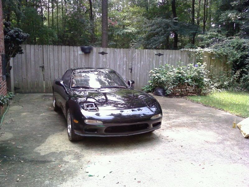
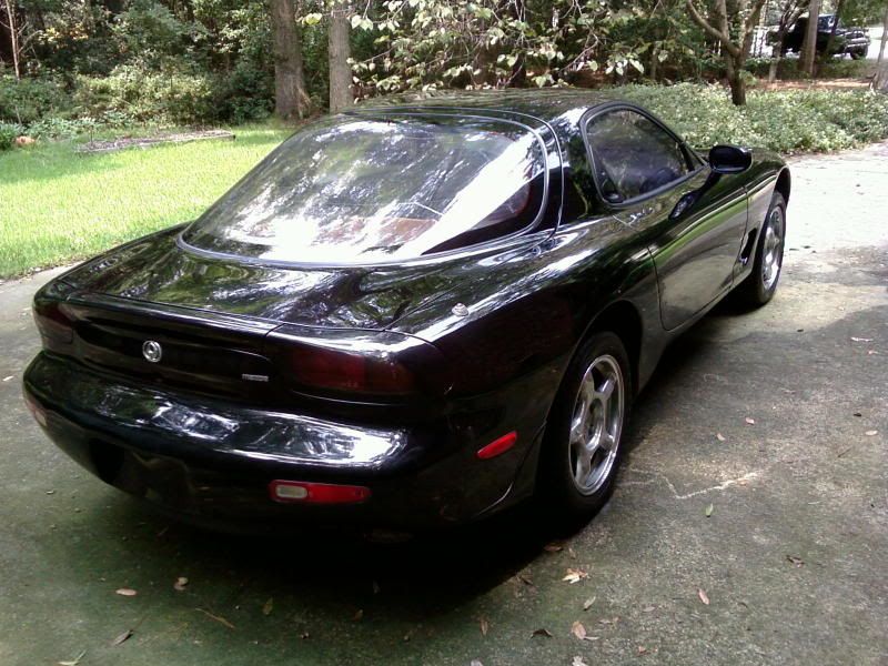
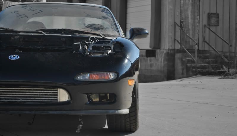
We'll start from the beginning when I bought the car last August.
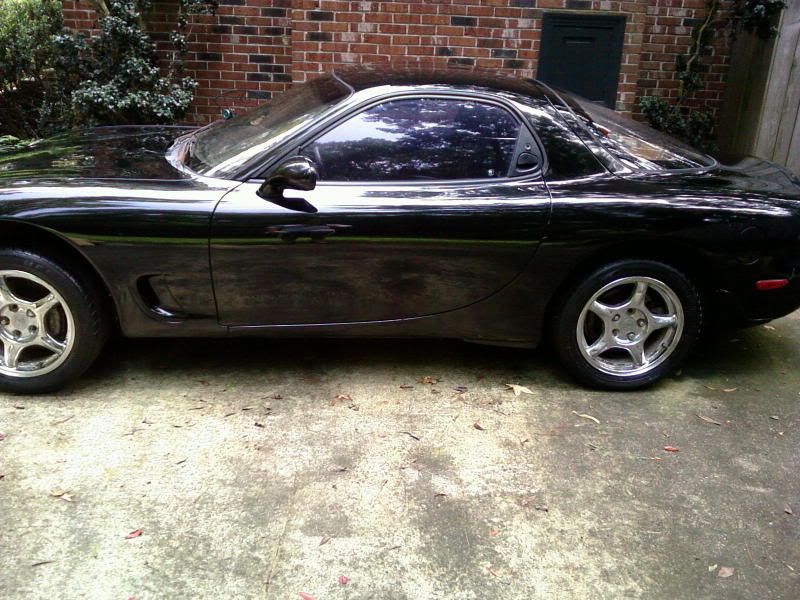
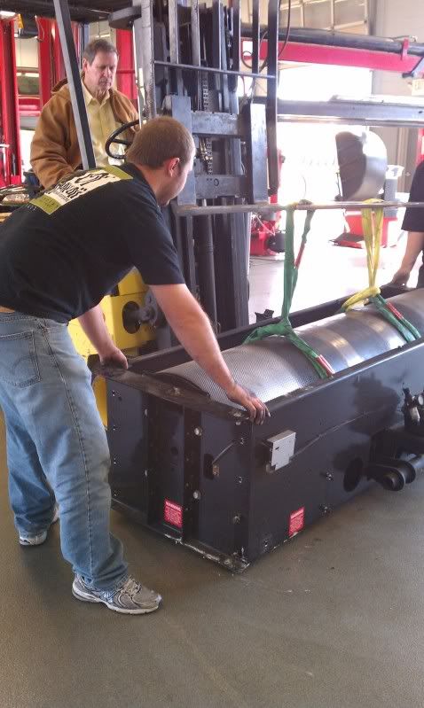
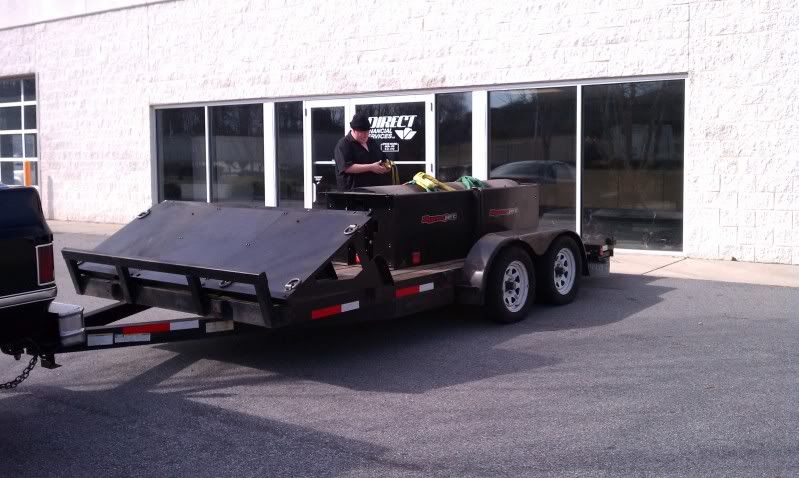
Packing the car up to ship to the shop:
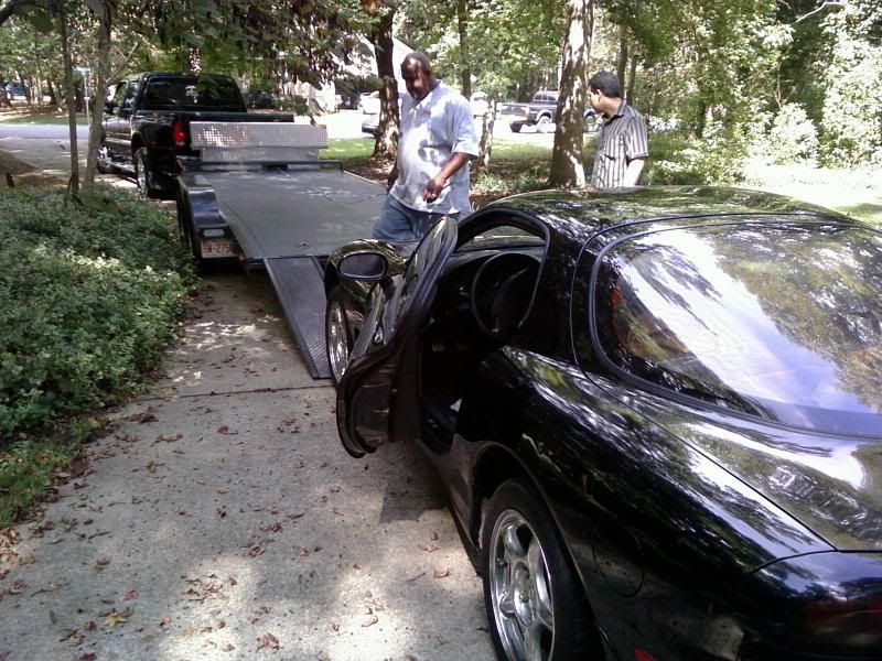
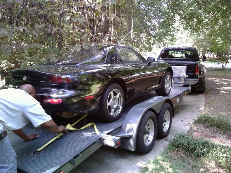
The truck, trailer, and car were just so beautiful I had to take some shots together.
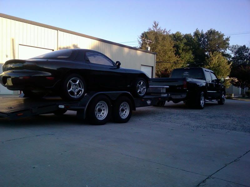
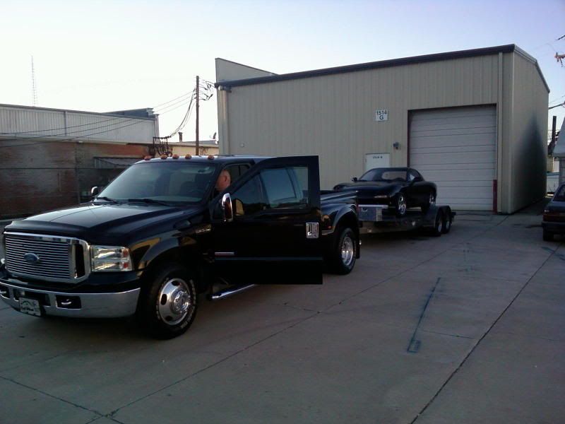
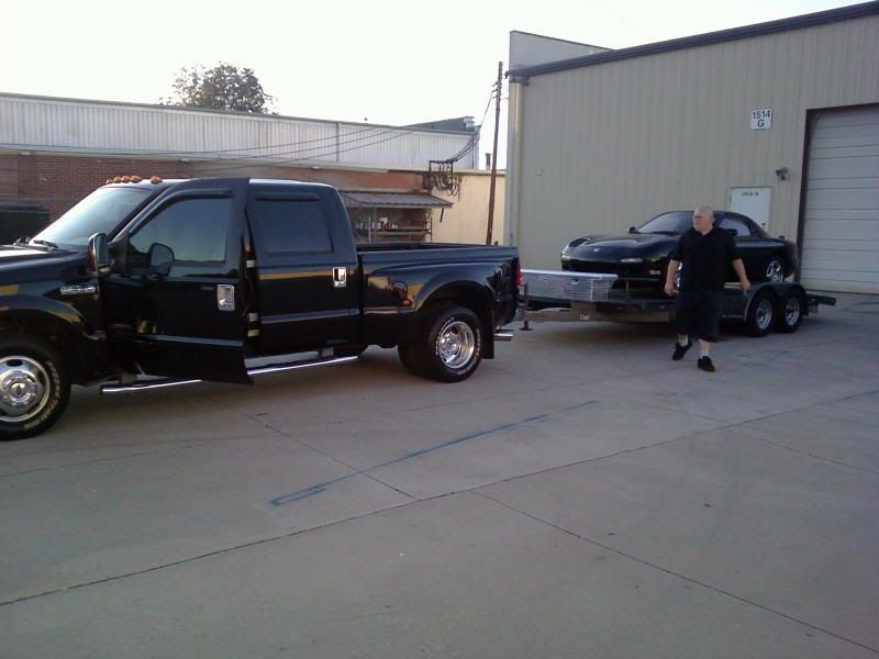
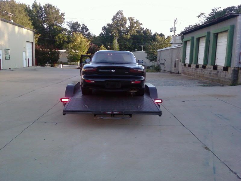
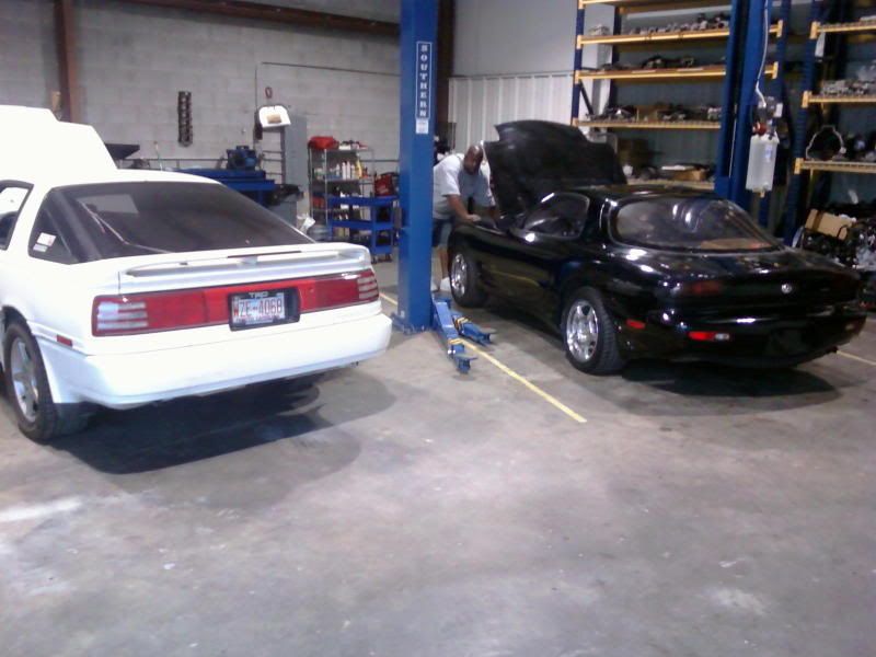
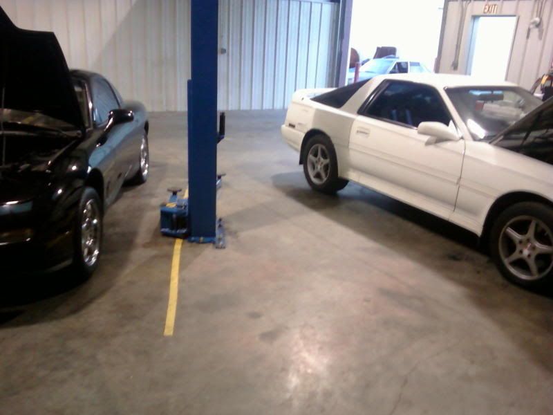
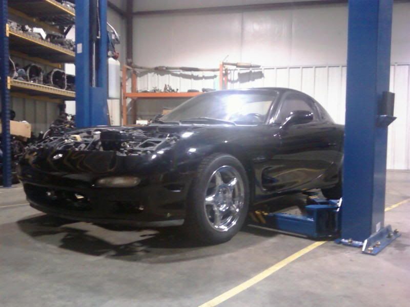
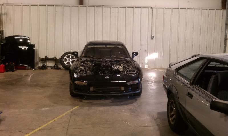
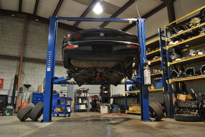
Wheel the car into the shop, and start pulling stuff apart. (The white MKIII is also mine.)
I'll post the pictures here and explain some of them, but regardless there should be quite a bit of information in here for those curious about the problems and solutions for this swap.
Feel free to ask questions, and if I don't know the answer I'll know someone that does.
We'll start from the beginning when I bought the car last August.
Packing the car up to ship to the shop:
The truck, trailer, and car were just so beautiful I had to take some shots together.
Wheel the car into the shop, and start pulling stuff apart. (The white MKIII is also mine.)
Thread Starter
Joined: Jul 2010
Posts: 499
Likes: 23
From: Greensboro, North Carolina
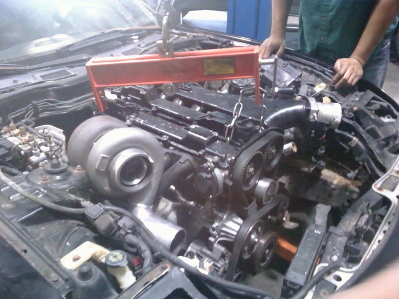
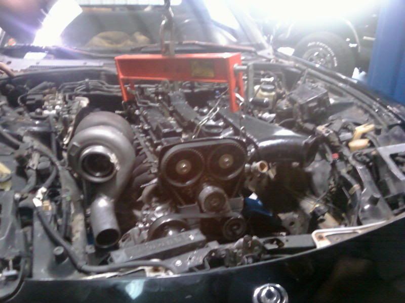
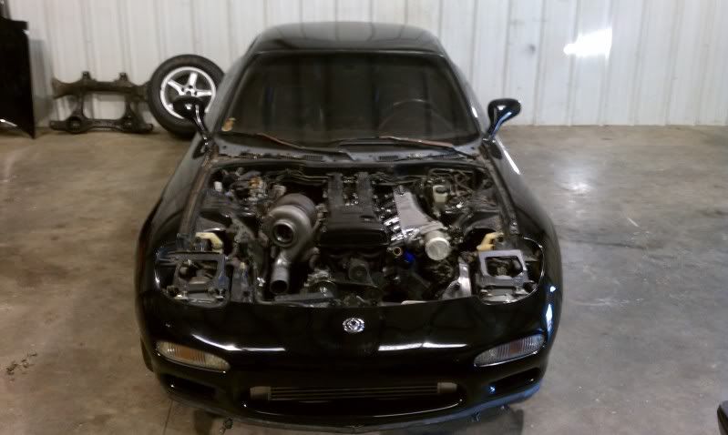
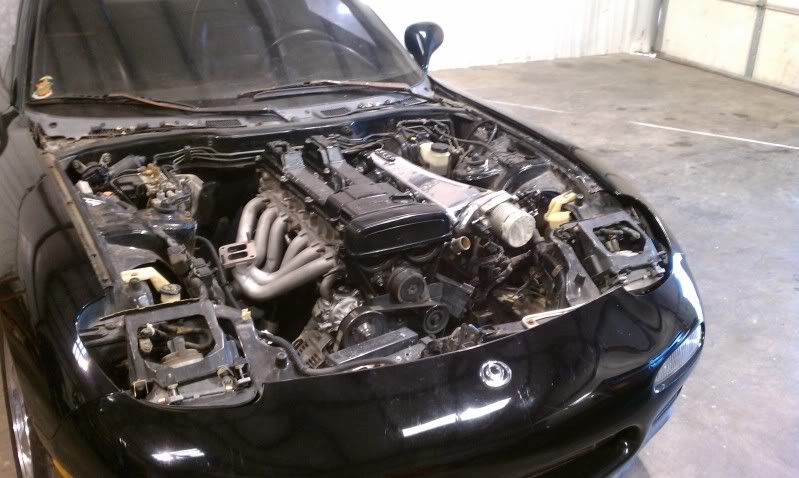
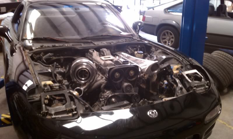
Mock-up engine, that later turned out to be a blown piece of ****:
I purchased a set of 2JZ swap mounts from e-bay that positioned the engine in the bay for measurement and later fabrication.
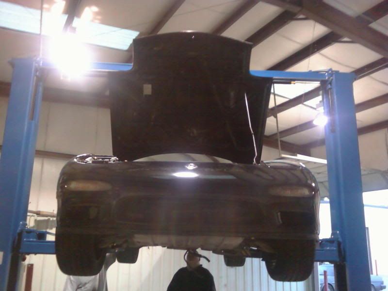
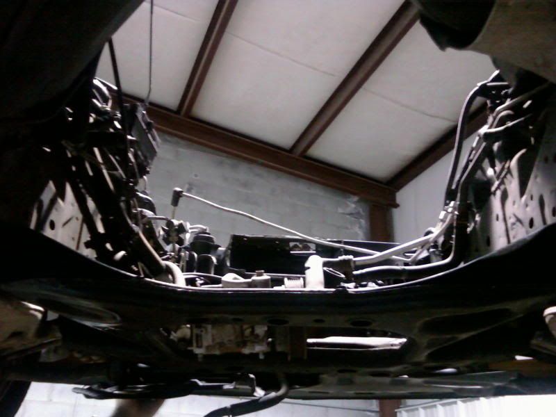

I purchased a set of 2JZ swap mounts from e-bay that positioned the engine in the bay for measurement and later fabrication.
Thread Starter
Joined: Jul 2010
Posts: 499
Likes: 23
From: Greensboro, North Carolina
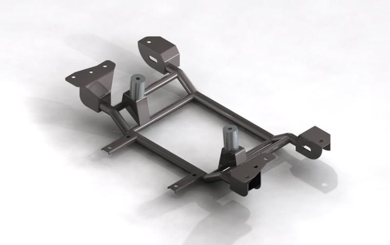
Next step was to design a subframe, so I got a hold of a Tech2 frame and reverse engineered it.
Here are a couple pics of the frame and models.

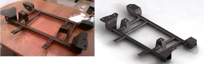
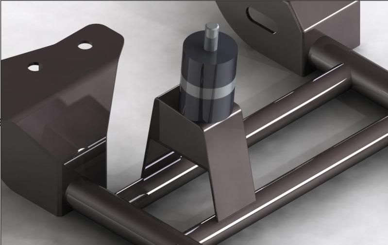
As for the mounts, I used some MIL spec hi-density UHMW stock with some 6061 T6 al stock.
If these fail, I'm going to revert to some Poly-urethanes I have at work.
Here are a couple pics of the frame and models.
As for the mounts, I used some MIL spec hi-density UHMW stock with some 6061 T6 al stock.
If these fail, I'm going to revert to some Poly-urethanes I have at work.
Thread Starter
Joined: Jul 2010
Posts: 499
Likes: 23
From: Greensboro, North Carolina
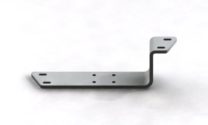
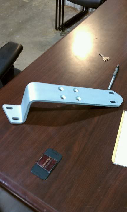
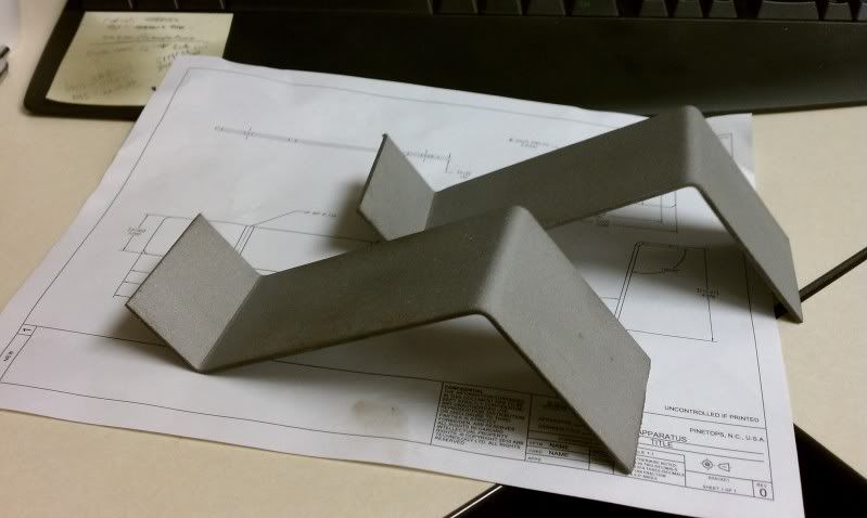
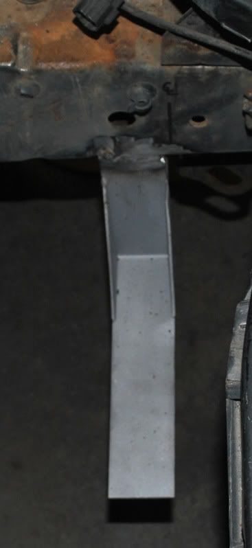
After the engine and sub-frame were in, I tackled the transmission mount.
I have access to a plethora of tools and equipment, so I decided to try a formed aluminum bracket for high weight to strength ratio.
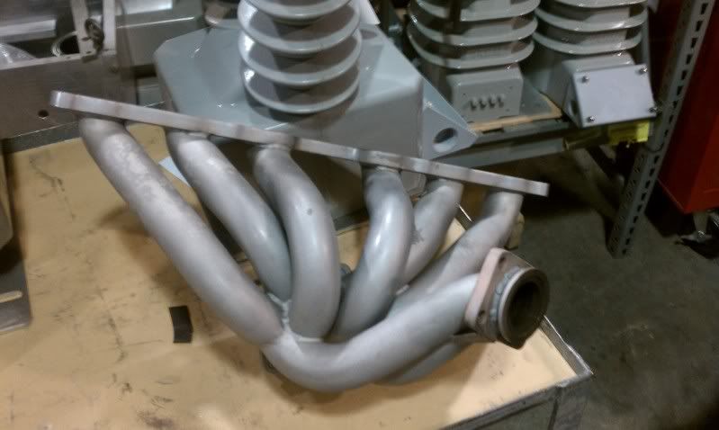
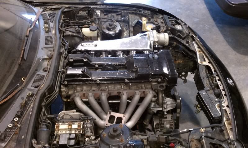
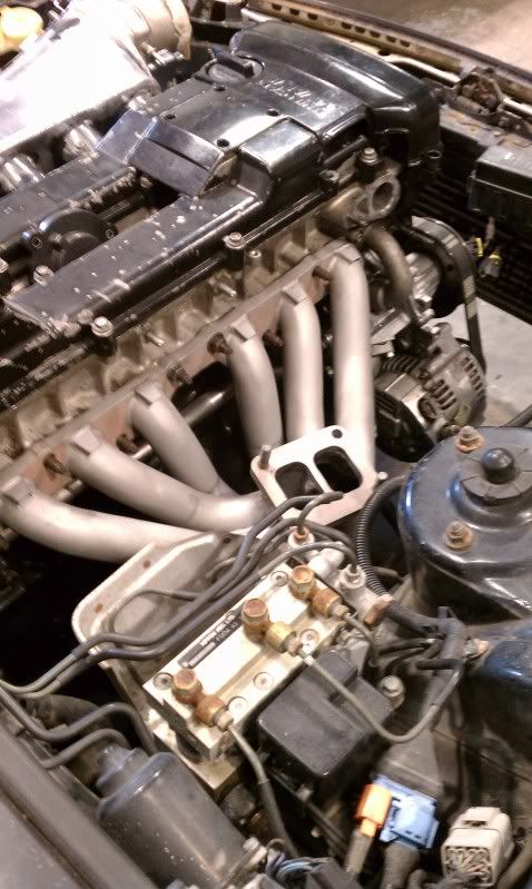
In the mean-time, I prepared my exhaust manifold for installing.

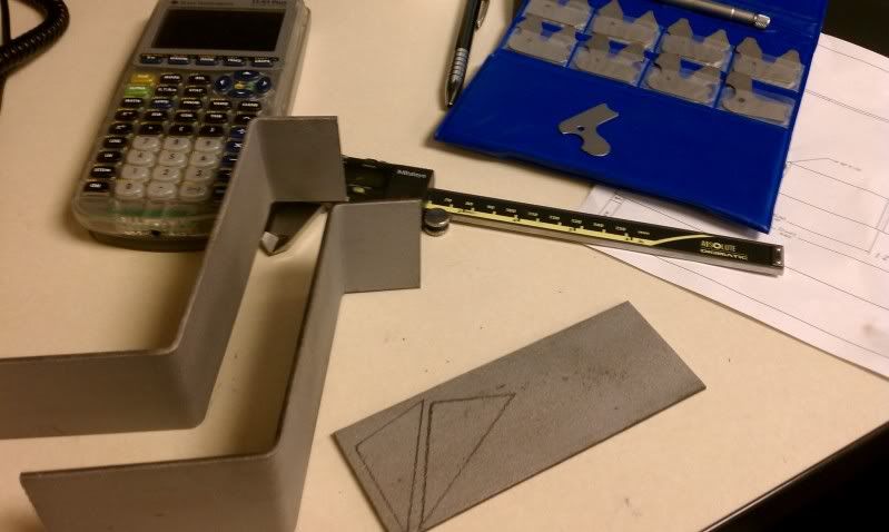
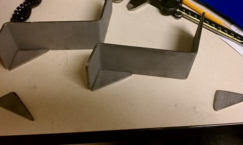
The first bracket came out "okay" but I wanted perfect, so I ended up making 2.
I have access to a plethora of tools and equipment, so I decided to try a formed aluminum bracket for high weight to strength ratio.
In the mean-time, I prepared my exhaust manifold for installing.
The first bracket came out "okay" but I wanted perfect, so I ended up making 2.
Thread Starter
Joined: Jul 2010
Posts: 499
Likes: 23
From: Greensboro, North Carolina
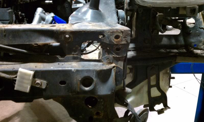
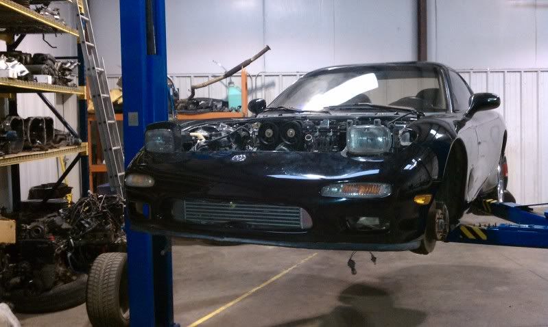
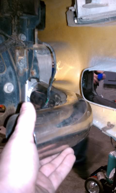
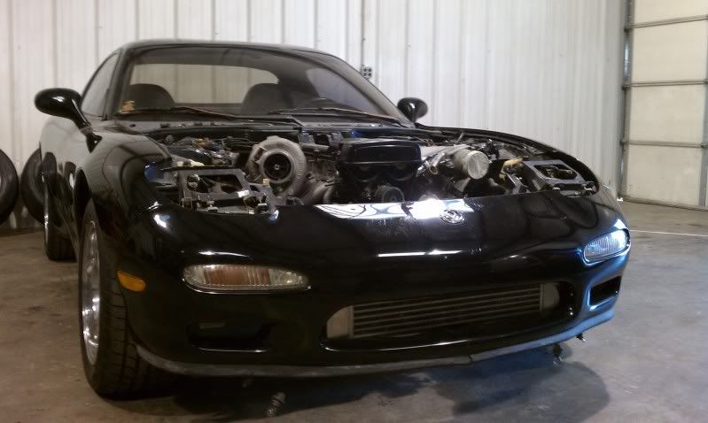
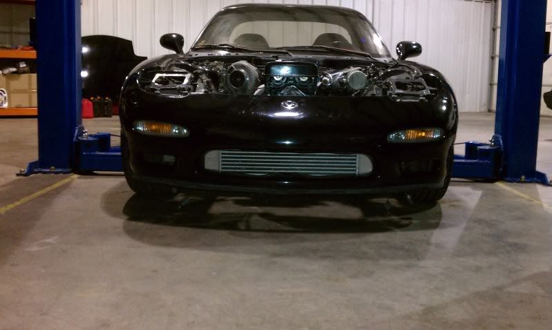
In preparation for the intercooler, I removed the front bumper cover as well as the fender liners. This FD has been in a fender bender, so the crash bar had a small pucker on the driver's side.
To mount it, I welded some .125" steel plate pads to my custom hanger brackets on the core, marked, drilled, and tapped.
Here are some pictures:
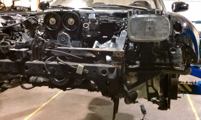
Collision damage:
Cleaning up the intercooler. (I used this cooler on my MKIII supra up to 650hp.)
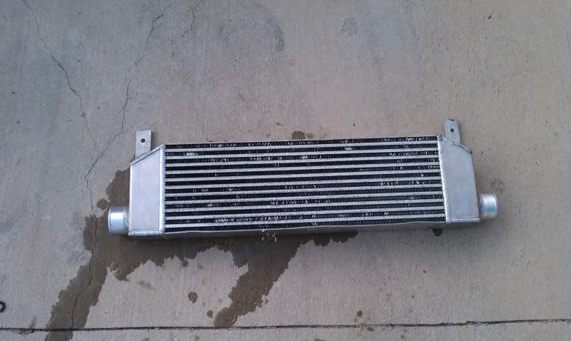
With some small pilot holes, we hung the intercooler in a couple places with zip-ties to get an idea where it will go.
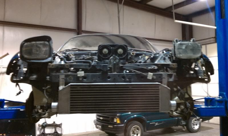
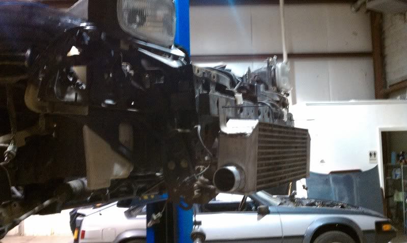
And here we are after welding in the pads, tapped, and bolted up:
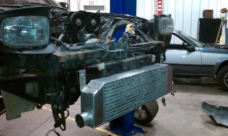
The duct in the OEM bumper needs to be trimmed a little so it's not rubbing on the core:
Here we are with the bumper back on. (I couldn't have a better fitting intercooler for this bumper.. I'm really happy with it.)
(ps, check out my hover car!)
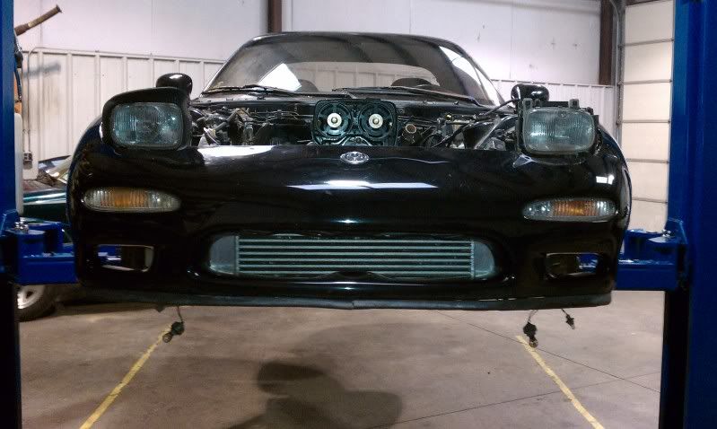
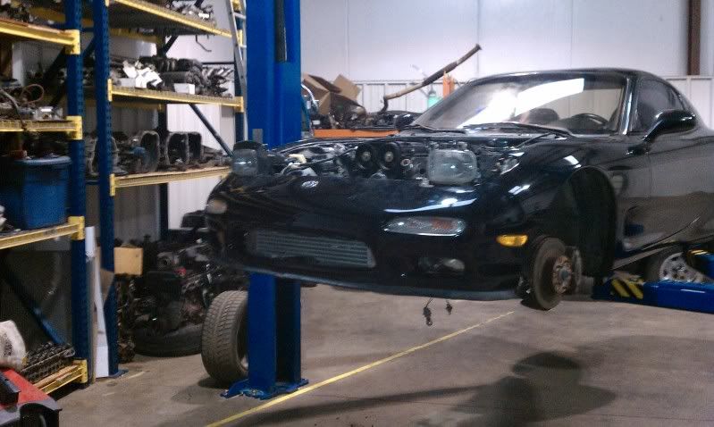
Next will be IC pipe routing, and it's got a great path.
To mount it, I welded some .125" steel plate pads to my custom hanger brackets on the core, marked, drilled, and tapped.
Here are some pictures:
Collision damage:
Cleaning up the intercooler. (I used this cooler on my MKIII supra up to 650hp.)
With some small pilot holes, we hung the intercooler in a couple places with zip-ties to get an idea where it will go.
And here we are after welding in the pads, tapped, and bolted up:
The duct in the OEM bumper needs to be trimmed a little so it's not rubbing on the core:
Here we are with the bumper back on. (I couldn't have a better fitting intercooler for this bumper.. I'm really happy with it.)
(ps, check out my hover car!)
Next will be IC pipe routing, and it's got a great path.
Thread Starter
Joined: Jul 2010
Posts: 499
Likes: 23
From: Greensboro, North Carolina
Since I only get to work on the RX7 on weekend, during the week I spend some time running simulations of components I design or would like to use.
I typically design for a FOS of 2.5 or greater on something like this.
For the engine sub frame, I choose a force comparable to a of 1,000 lbs in various directions to highlight any areas of concern.
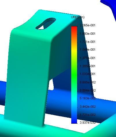
In the Tech2 style subframe, assuming an basic AISI 304 material I was able to determine a couple key areas that had zone where the stress surpassed the yield strength of the material. In an average weld, depending on the filler metal or post annealing the strength of bond can be as low as 70% of the yield strength. So I'll be keeping an eye on these areas.
Here are a couple screen shots of the calculation results.
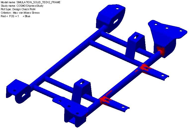
Here shows a small buckling scenario at the weld joint near the steering rack engine standoff interface.
This was simulated at 1,000lbs static force with the car frame mounting locations restrained. (The scaling is 16X.)
I typically design for a FOS of 2.5 or greater on something like this.
For the engine sub frame, I choose a force comparable to a of 1,000 lbs in various directions to highlight any areas of concern.
In the Tech2 style subframe, assuming an basic AISI 304 material I was able to determine a couple key areas that had zone where the stress surpassed the yield strength of the material. In an average weld, depending on the filler metal or post annealing the strength of bond can be as low as 70% of the yield strength. So I'll be keeping an eye on these areas.
Here are a couple screen shots of the calculation results.
Here shows a small buckling scenario at the weld joint near the steering rack engine standoff interface.
This was simulated at 1,000lbs static force with the car frame mounting locations restrained. (The scaling is 16X.)
Trending Topics
Thread Starter
Joined: Jul 2010
Posts: 499
Likes: 23
From: Greensboro, North Carolina
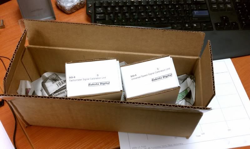
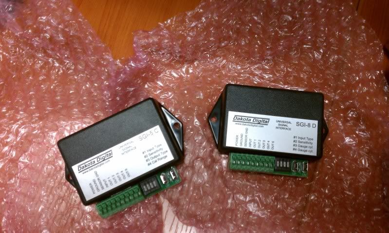
Acquired my dakota digital signal converters for my speedometer and tachometer.
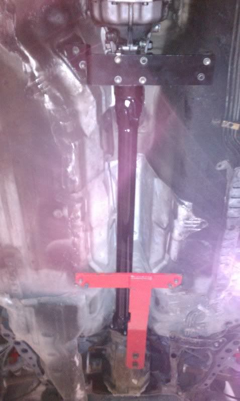
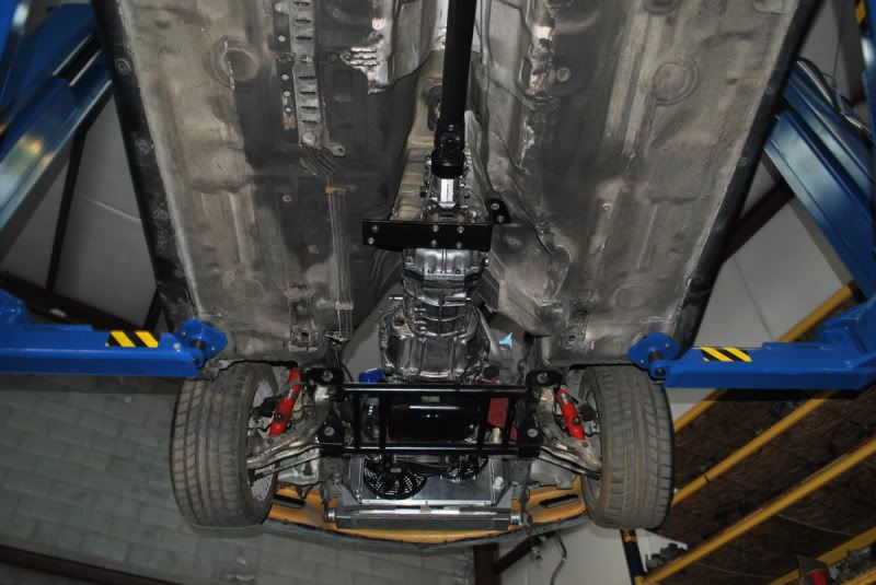
Began work on the transmission brace:
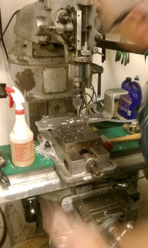
It's going to look really nice once finished:
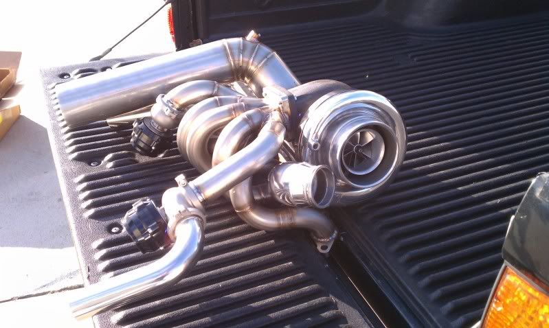
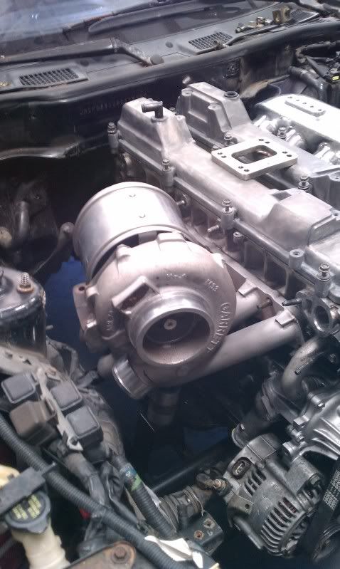
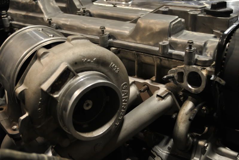
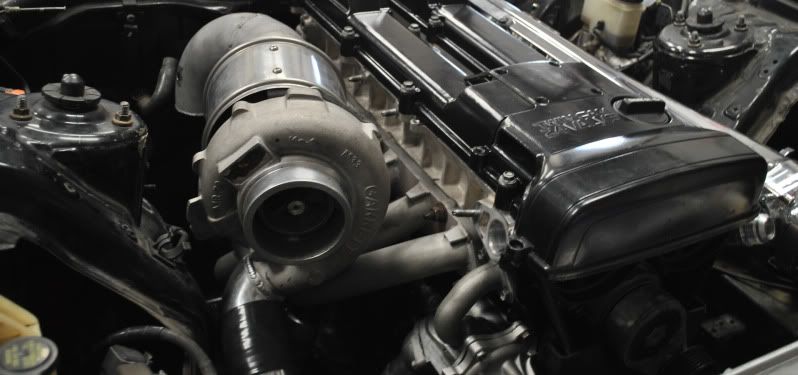
I was swapping out different turbos I have laying around, and had a little fun:
The prepped and media blasted HKS clone. (I'm guessing it's a clone.. No idea where it came from.)
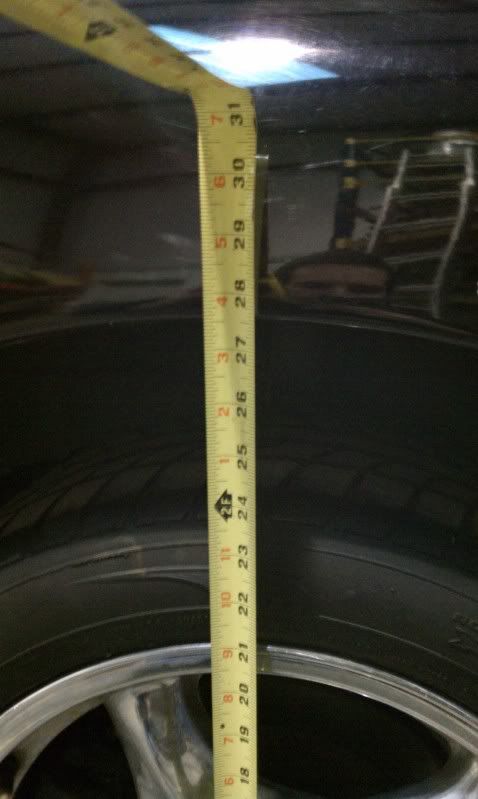
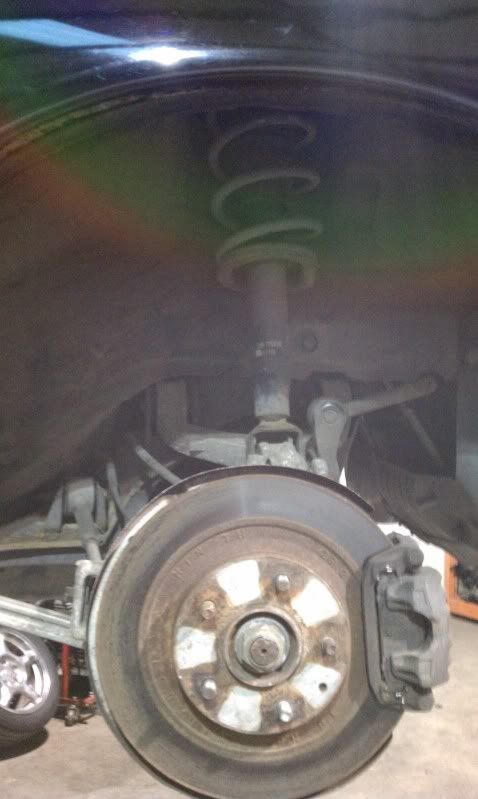
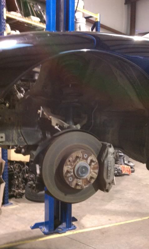
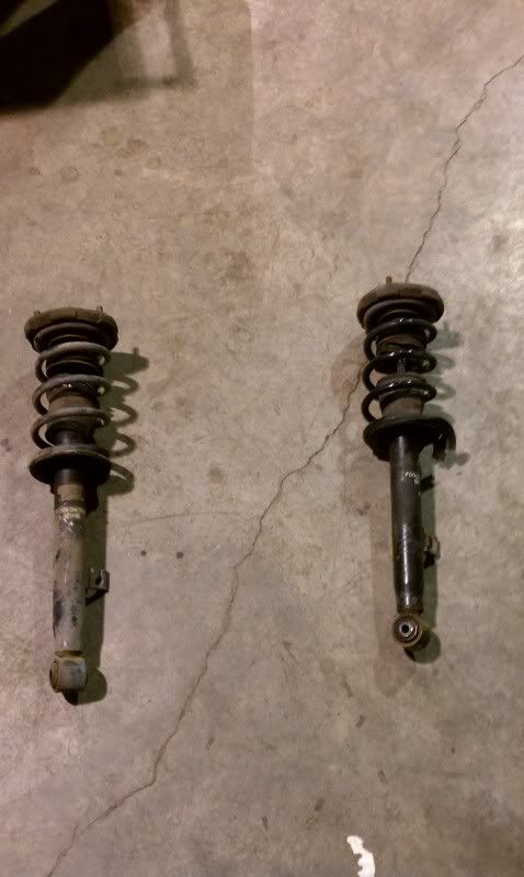
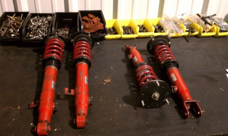
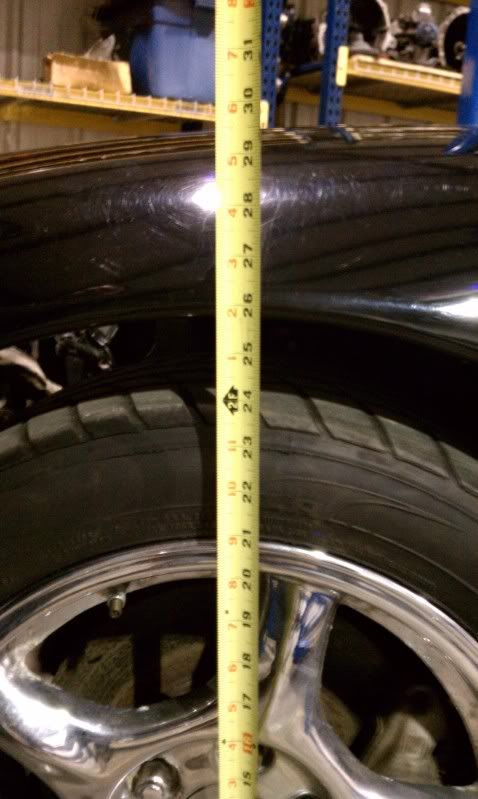
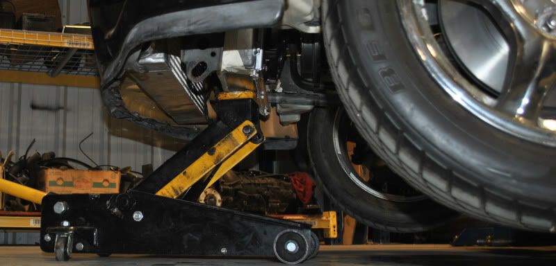
Pulling out the front suspension:
Original height for reference:
Began work on the transmission brace:
It's going to look really nice once finished:
I was swapping out different turbos I have laying around, and had a little fun:
The prepped and media blasted HKS clone. (I'm guessing it's a clone.. No idea where it came from.)
Pulling out the front suspension:
Original height for reference:
Thread Starter
Joined: Jul 2010
Posts: 499
Likes: 23
From: Greensboro, North Carolina
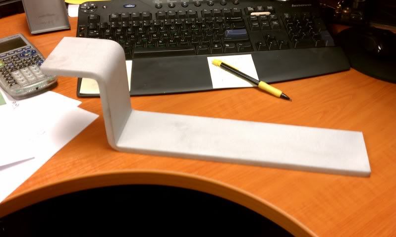
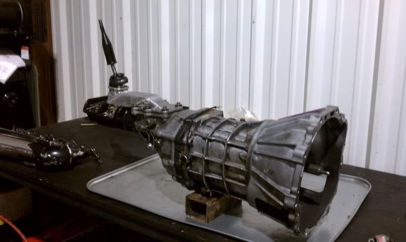
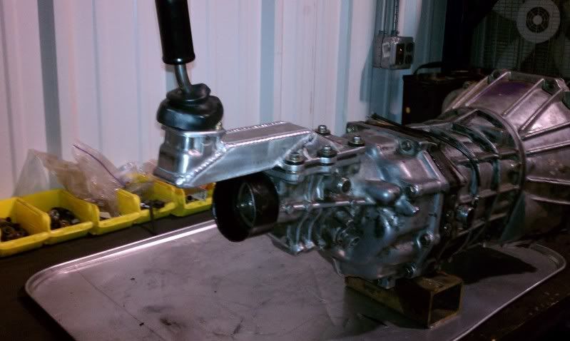
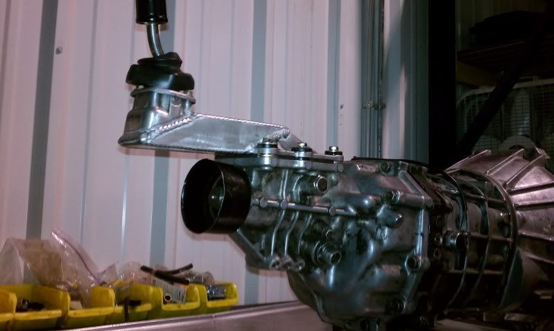
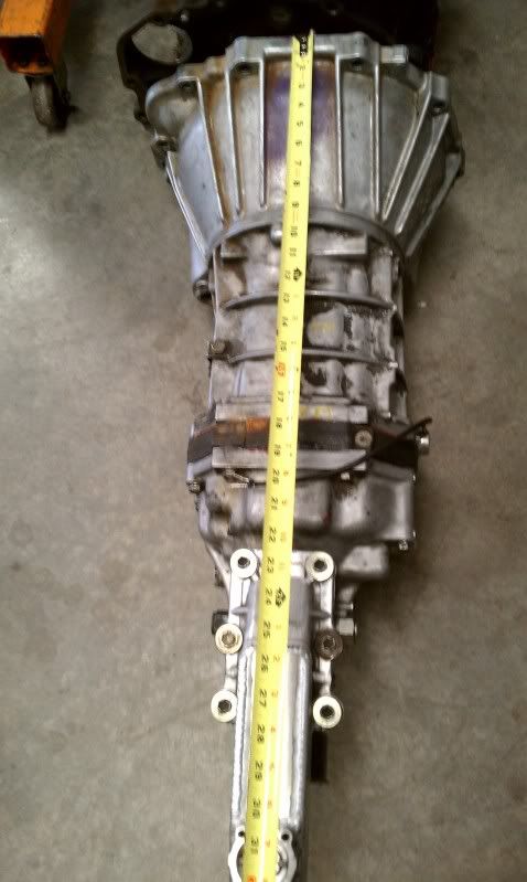
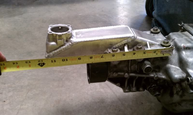
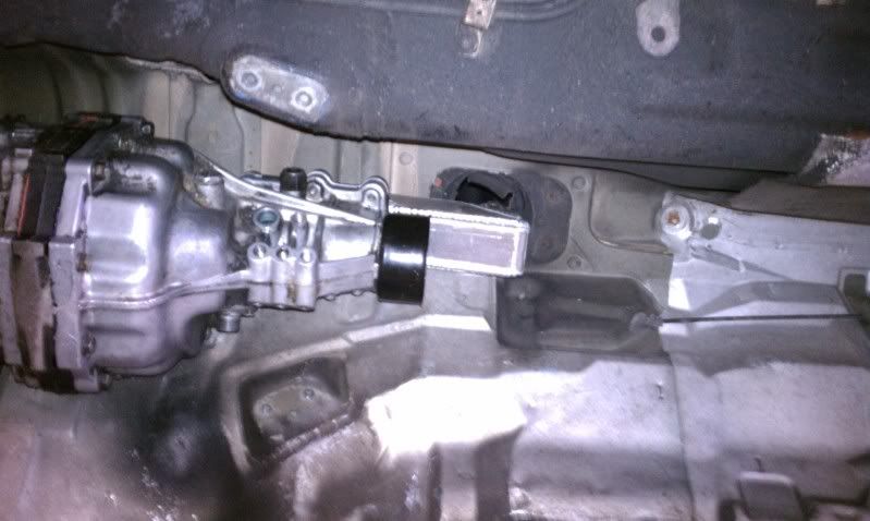
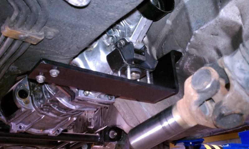
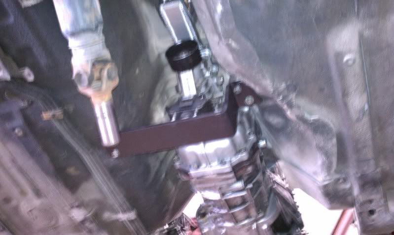
Here is the transmission shifter extension portion of the swap.
Aaron at Driftmotion did the shifter housing extension.
Here are a couple pics of the tranny
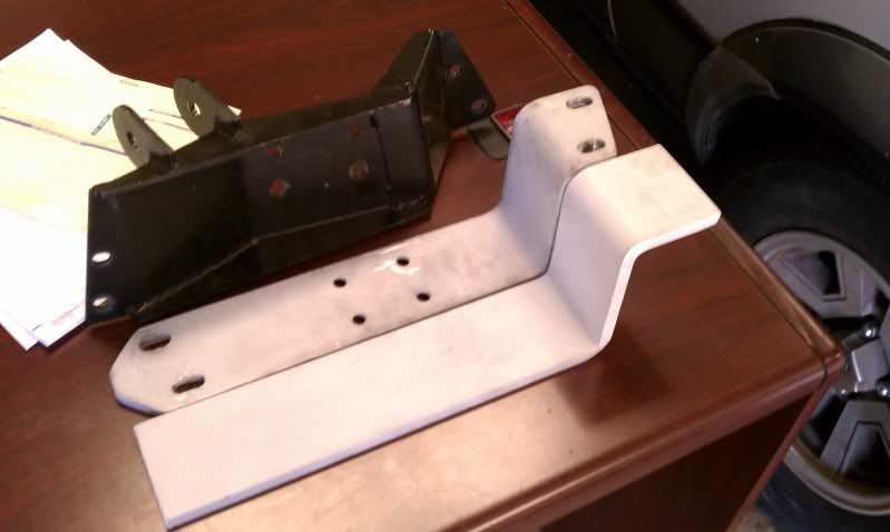
Here's the new transmission brace... looks much better.
I haven't trimmed the sides yet, or added the standoffs for the rubber mount.
Aaron at Driftmotion did the shifter housing extension.
Here are a couple pics of the tranny
Here's the new transmission brace... looks much better.
I haven't trimmed the sides yet, or added the standoffs for the rubber mount.
Thread Starter
Joined: Jul 2010
Posts: 499
Likes: 23
From: Greensboro, North Carolina
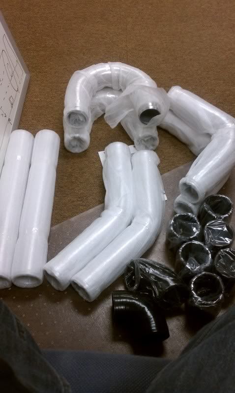
Purchased a standard CXRacing IC pipe kit to piece together my bends.
They look decent.
We'll see how they work out:
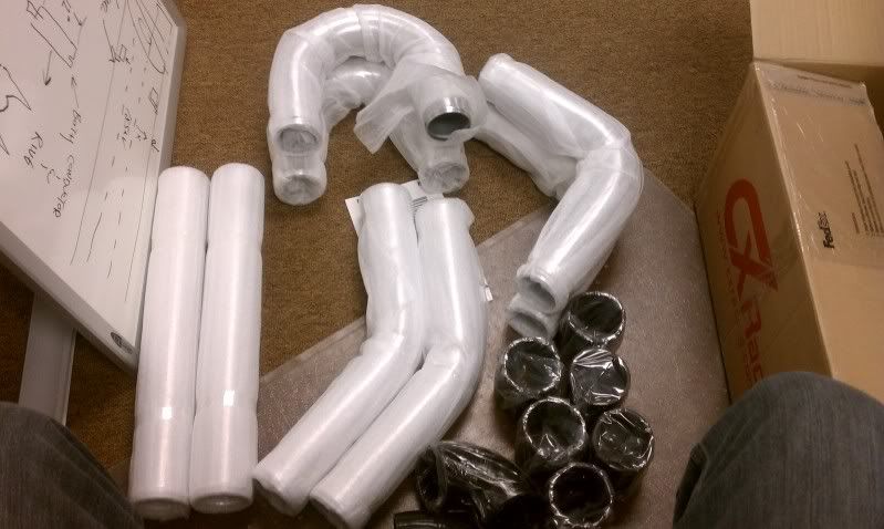
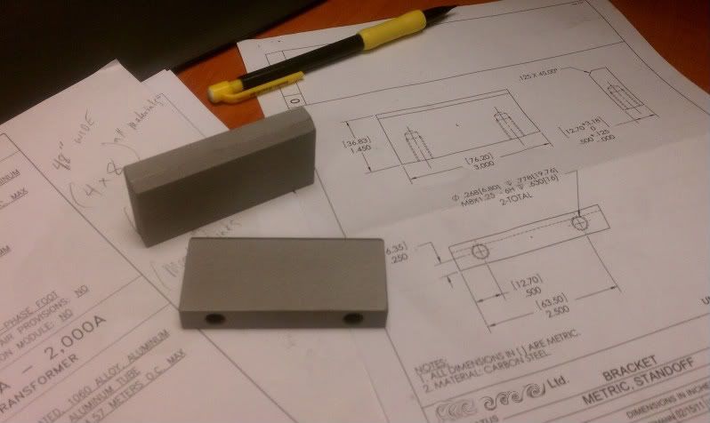
Milled off a couple standoffs that I intend to weld to my transmission mount.
Some other misc. parts to fabricate the exhaust:
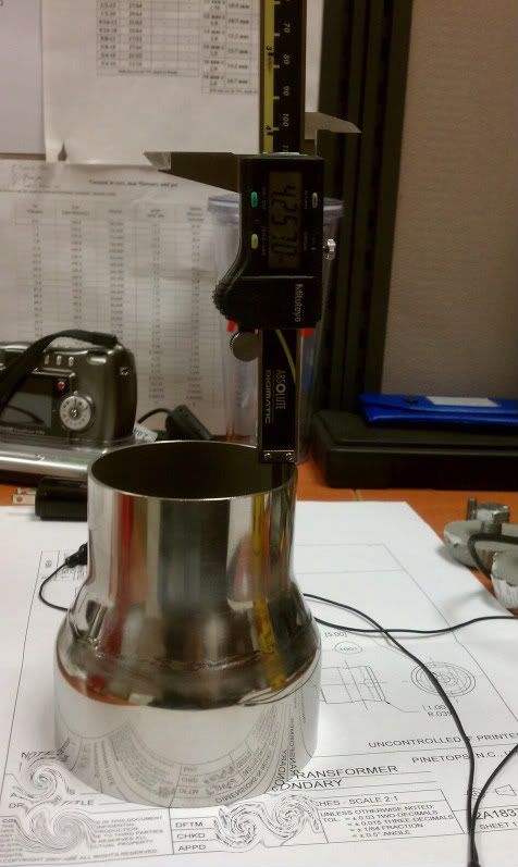
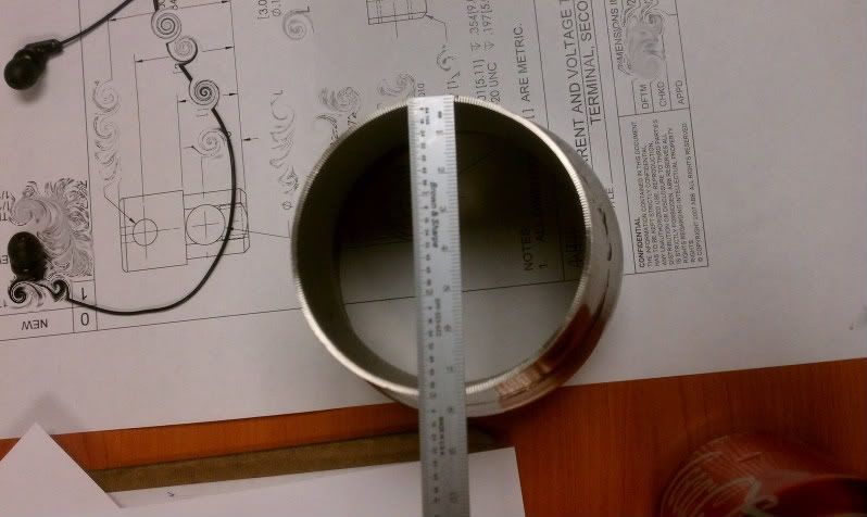
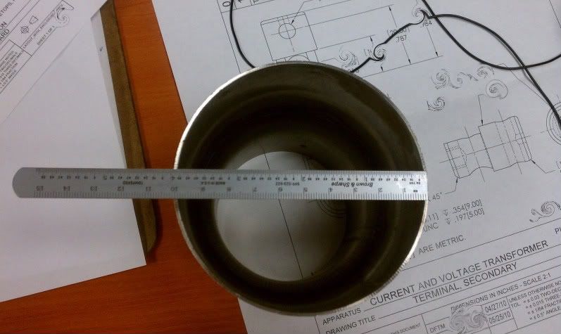
I got my 316 stainless reducer to make my down pipe. Currently, it's a 4" pipe with 4" v-band flange. What I would like to do for the time being, is use my GT4088 with the 3" turbine exit and reuse my 4" downpipe.
So I'll go from 3" to 4" to open dp.
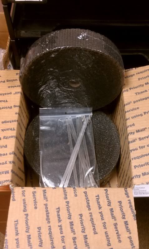
Also got some fiberglass heat shielding wrap for whatever I'd like to insulate.
About 100' by 2" here.
They look decent.
We'll see how they work out:
Milled off a couple standoffs that I intend to weld to my transmission mount.
Some other misc. parts to fabricate the exhaust:
I got my 316 stainless reducer to make my down pipe. Currently, it's a 4" pipe with 4" v-band flange. What I would like to do for the time being, is use my GT4088 with the 3" turbine exit and reuse my 4" downpipe.
So I'll go from 3" to 4" to open dp.
Also got some fiberglass heat shielding wrap for whatever I'd like to insulate.
About 100' by 2" here.
Thread Starter
Joined: Jul 2010
Posts: 499
Likes: 23
From: Greensboro, North Carolina
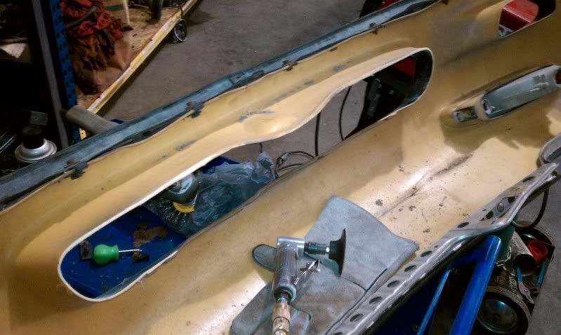
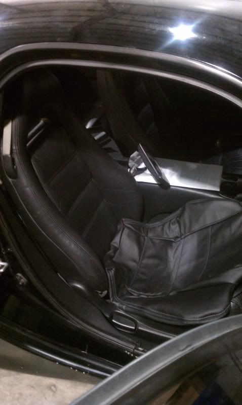
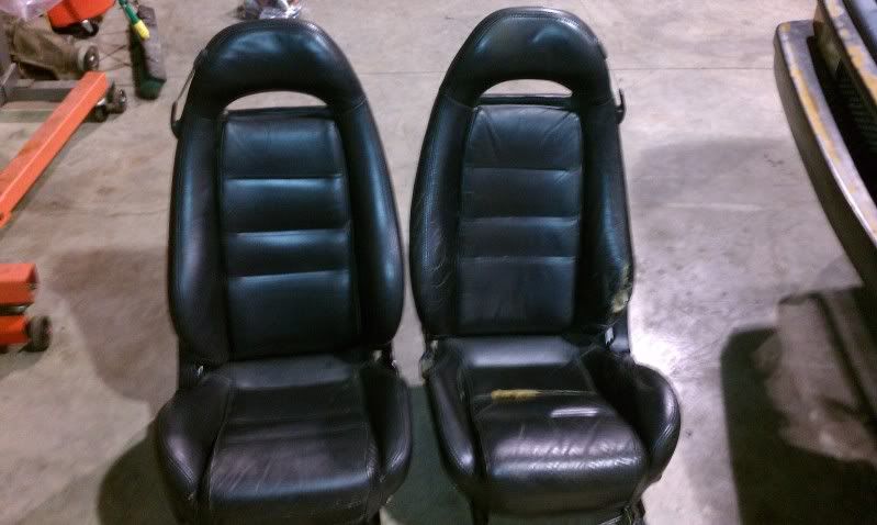
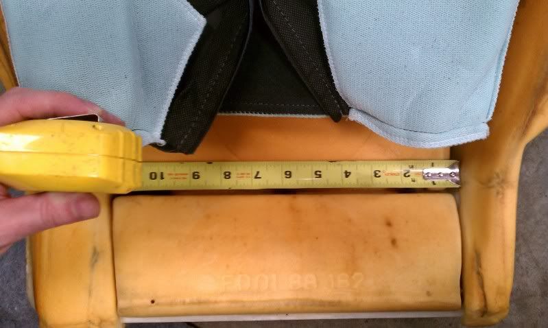
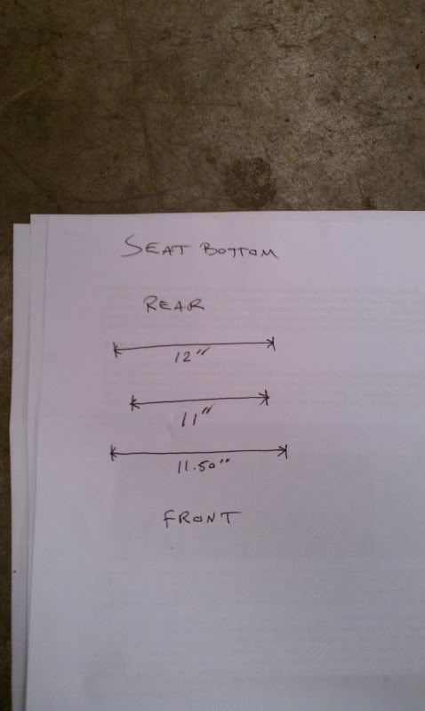
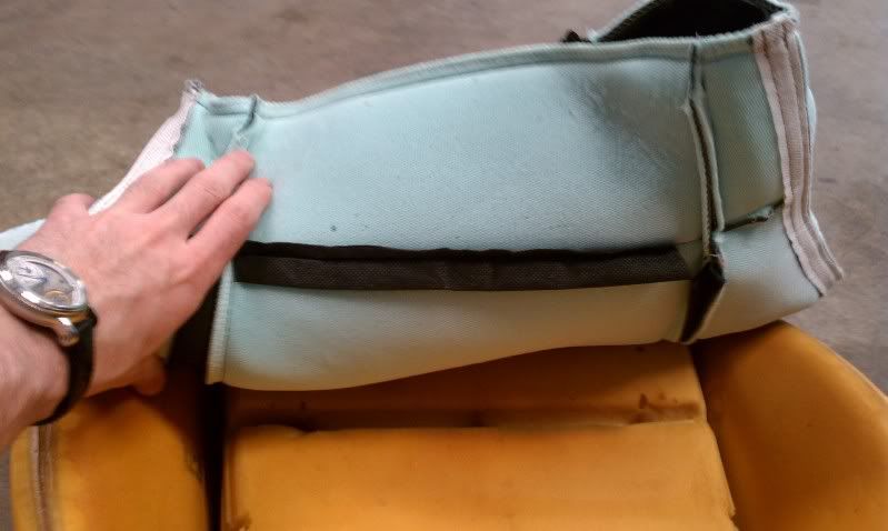
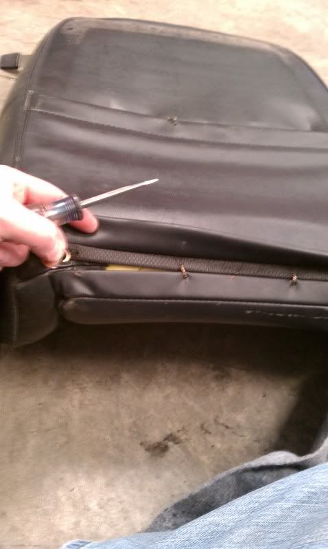
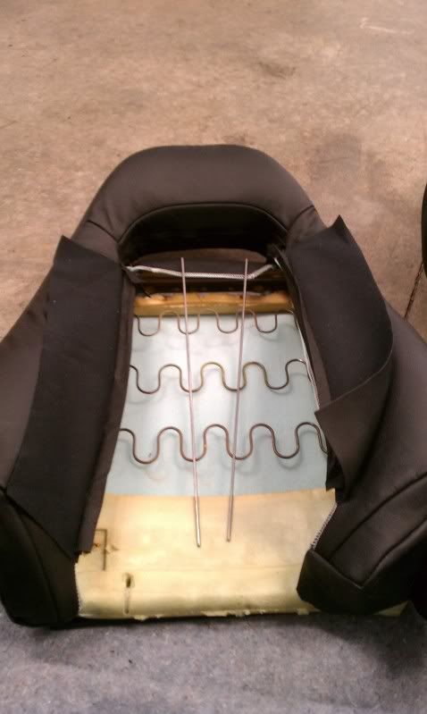
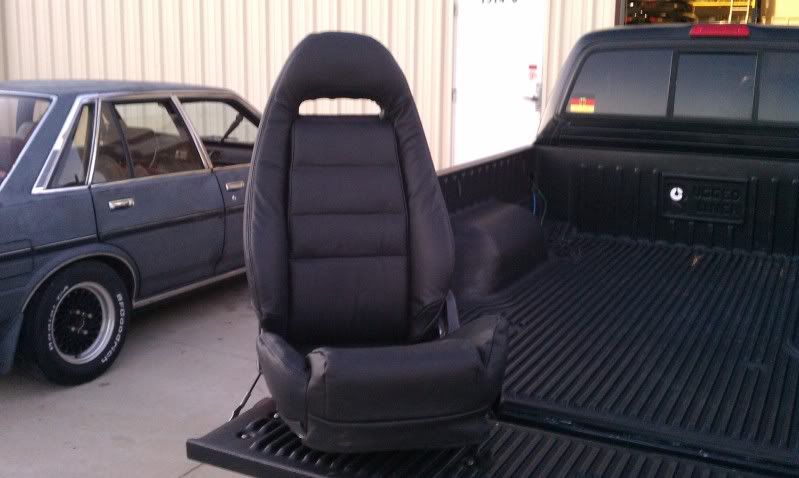
Then I wanted to learn a little upholstery work.
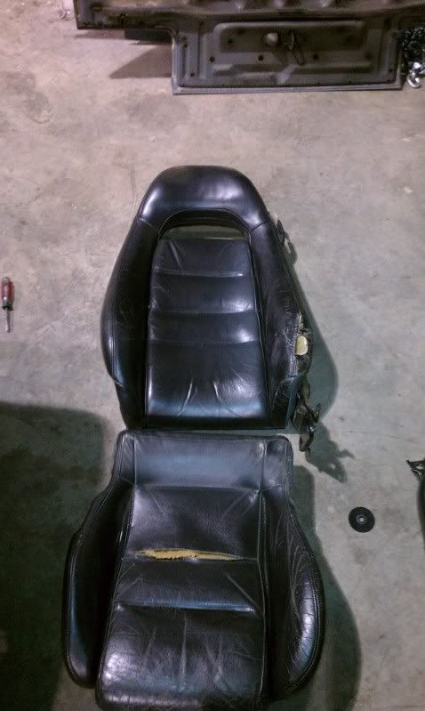
I figured I'd try my hand at some upholstery work, and re-finish the RX7's leather seats.
Now, I have no real experience doing this... so I was delighted they came out half decent. Here are a couple pictures of the process.
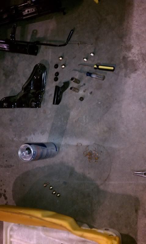
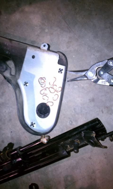
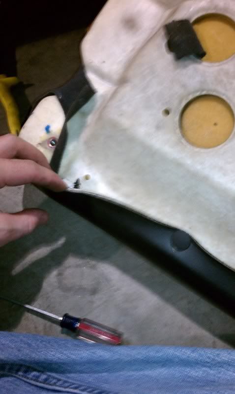
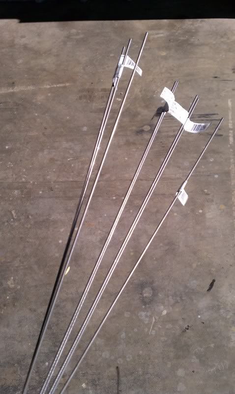
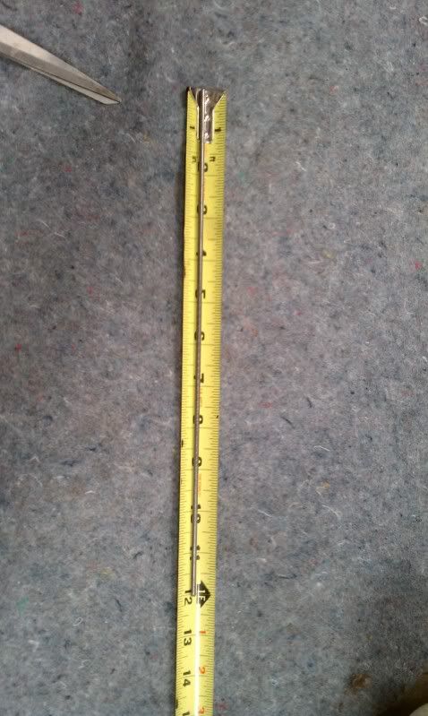
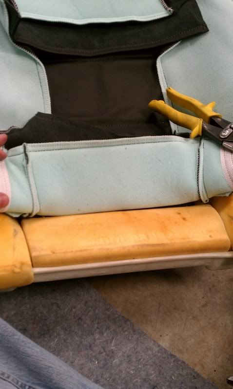
Instead of using the vinyl trim pieces to pull in the material to the foam, I purchased some aluminum rods to run through the eyelets to give a nice flat plane to pull against the seat leather:
I figured I'd try my hand at some upholstery work, and re-finish the RX7's leather seats.
Now, I have no real experience doing this... so I was delighted they came out half decent. Here are a couple pictures of the process.
Instead of using the vinyl trim pieces to pull in the material to the foam, I purchased some aluminum rods to run through the eyelets to give a nice flat plane to pull against the seat leather:
Thread Starter
Joined: Jul 2010
Posts: 499
Likes: 23
From: Greensboro, North Carolina
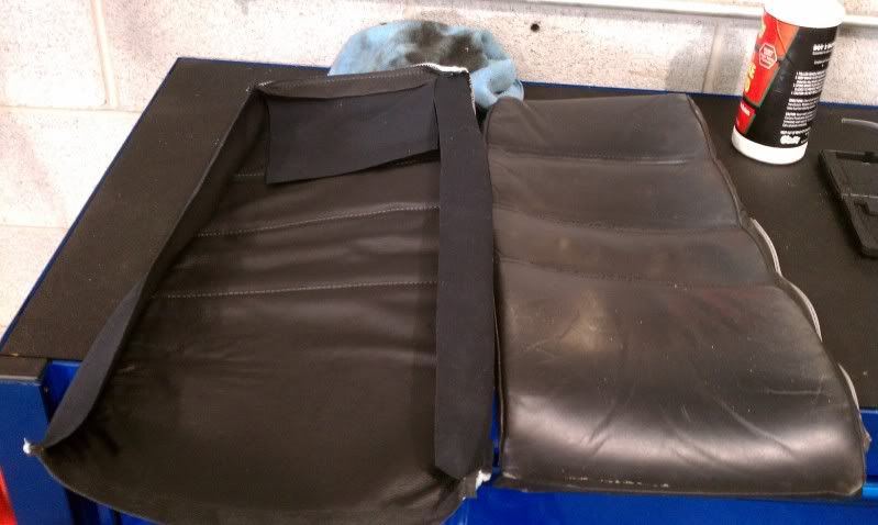
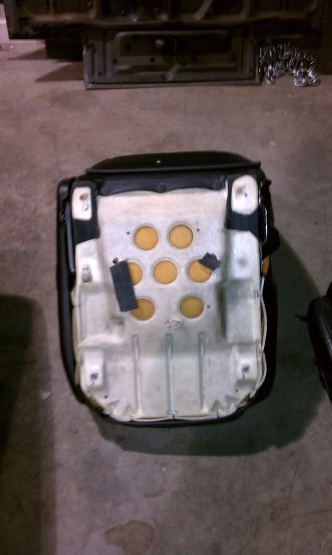
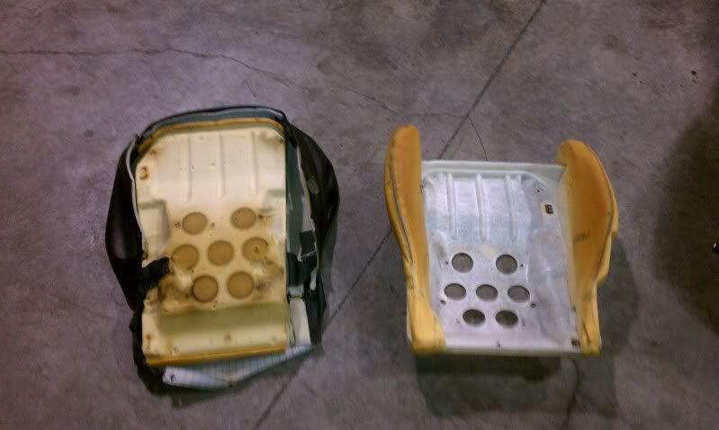
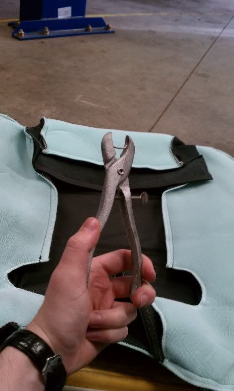
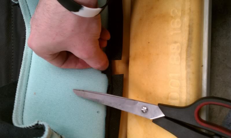
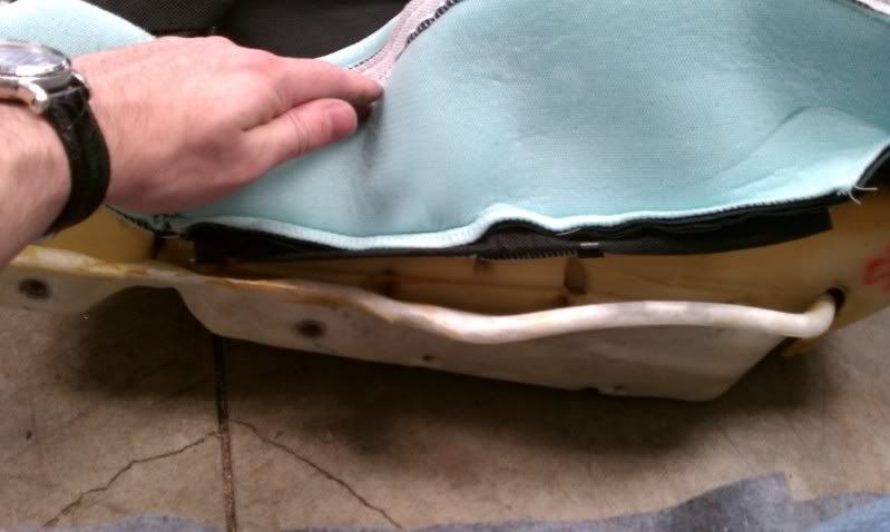
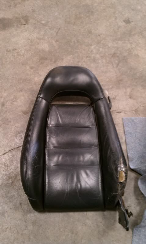
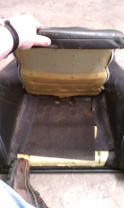
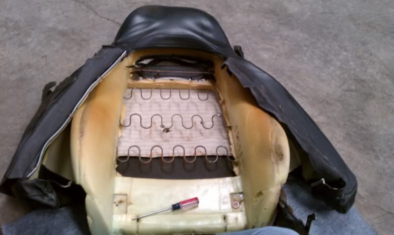
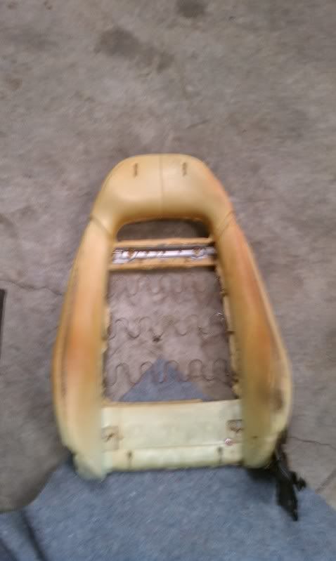
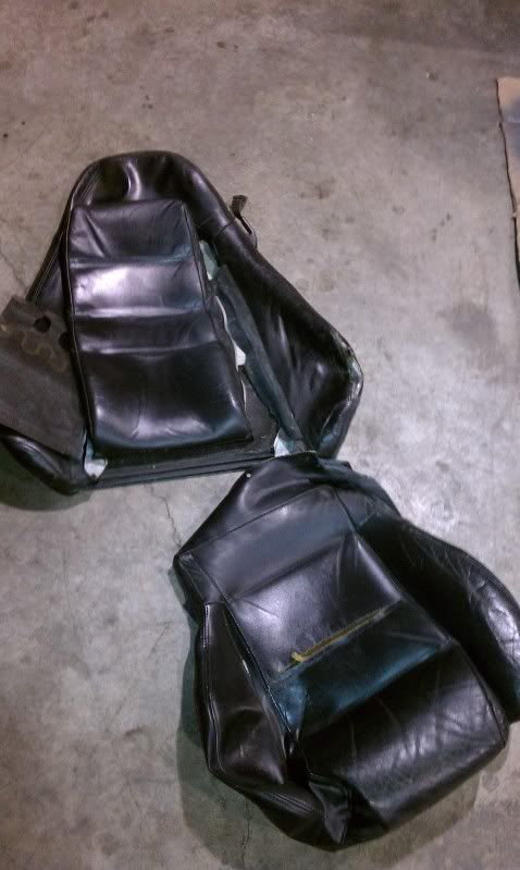
Here are the remains of the worn out leather stripped from the seats:
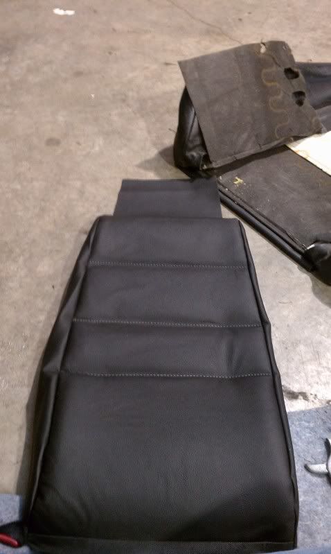
Still could use a little more pulling and tucking, but overall I think I did a pretty decent job for my first time

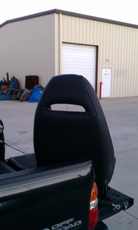
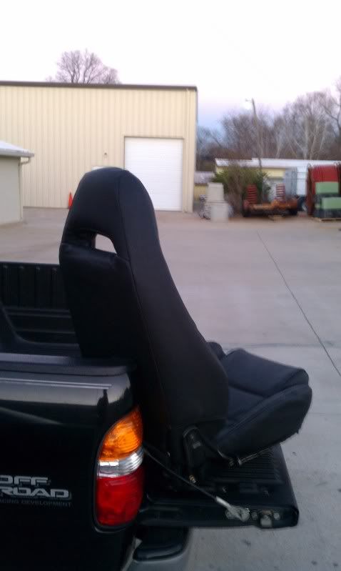
All in all, it took me about 10 hours to do one seat. The next one should take much less.
Thread Starter
Joined: Jul 2010
Posts: 499
Likes: 23
From: Greensboro, North Carolina
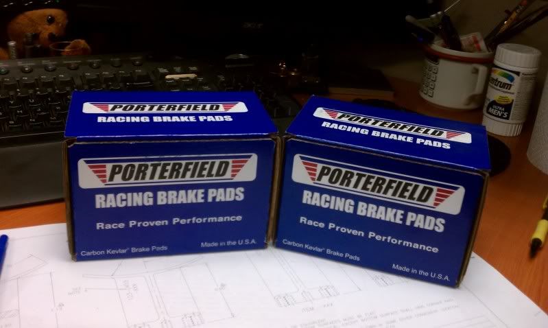
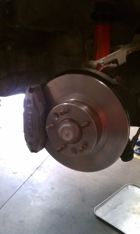
Replaced all the brakes with new rotors and Porties:
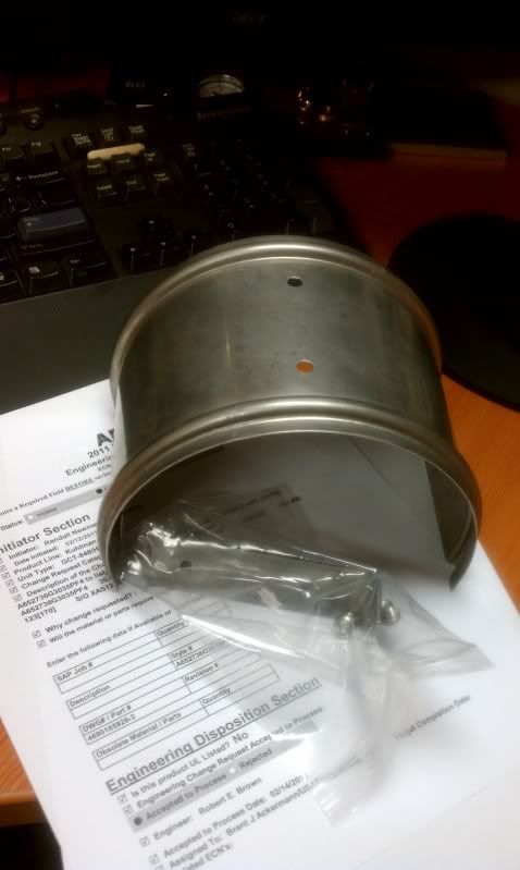
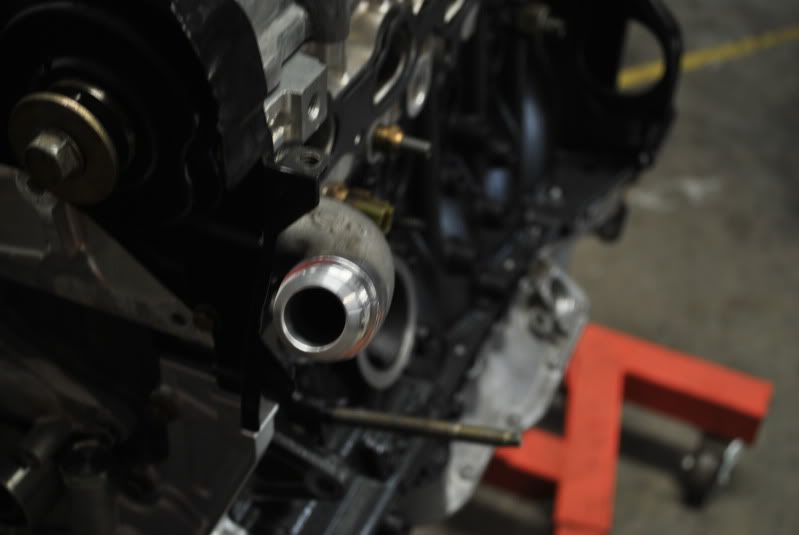
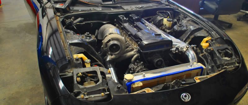
New heat shield from ATP Turbo:
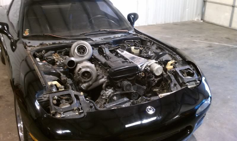
Did a little bit of work on the 7, but check out what we got one morning.;-)
Seth came for a visit today to bring me my manifold for the supra, so I took the opportunity to see what my billet turbo would look like on the. Rx7
Got the driveshaft installed, and the fuel tank drained ready for dropping.
New heat shield from ATP Turbo:
Did a little bit of work on the 7, but check out what we got one morning.;-)
Seth came for a visit today to bring me my manifold for the supra, so I took the opportunity to see what my billet turbo would look like on the. Rx7
Got the driveshaft installed, and the fuel tank drained ready for dropping.
Thread Starter
Joined: Jul 2010
Posts: 499
Likes: 23
From: Greensboro, North Carolina
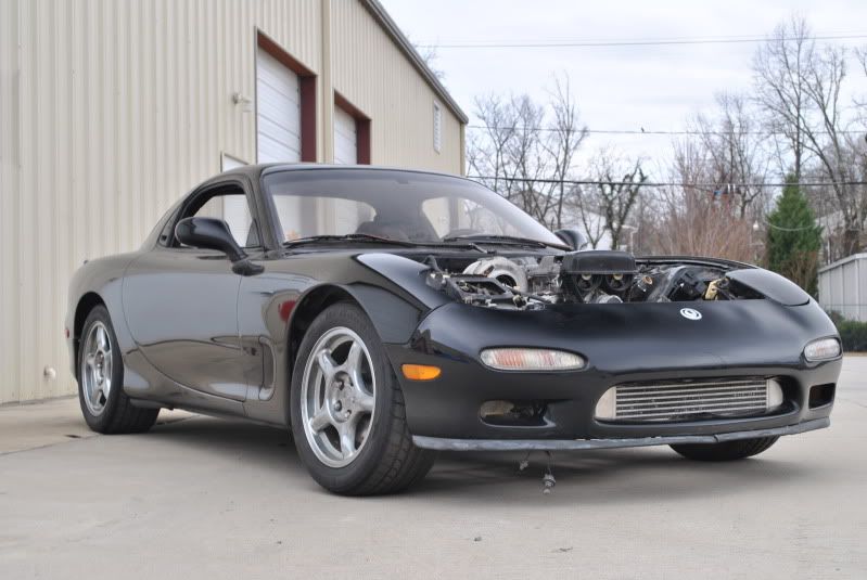
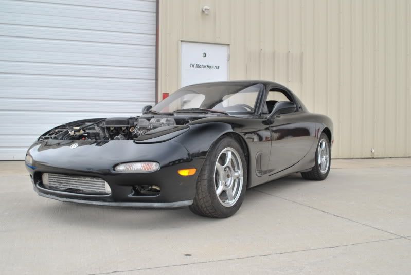
Gonna put the brakes on this project.
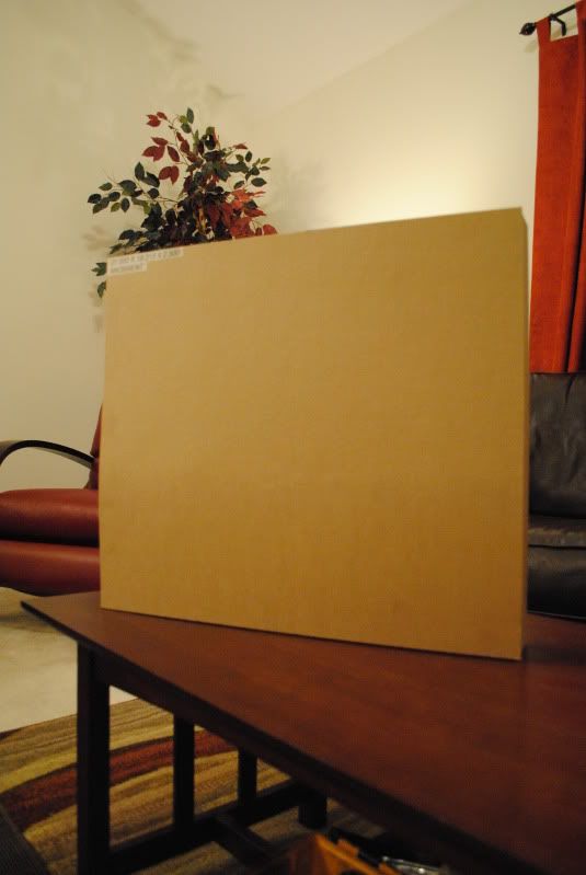
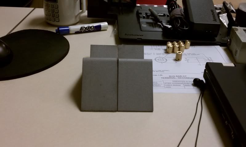
Bought a new camera, so the pictures from here on out will be better:
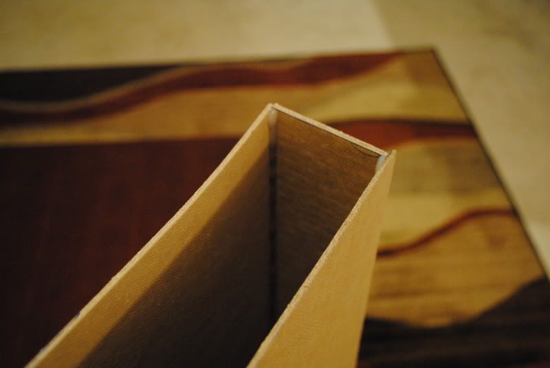
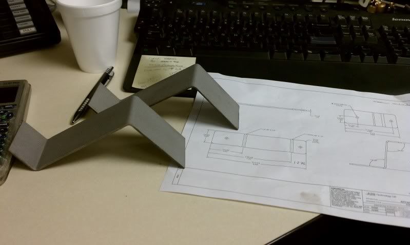
Before heading home today, I took some scrap pieces of pressboard, sheared out 4 pieces to some dimensions I'm thinking of making a radiator to.
It's always nice to have a model to work with in the car.
I epoxied the sides together, so it's a real quick and dirty mock radiator.


Thread Starter
Joined: Jul 2010
Posts: 499
Likes: 23
From: Greensboro, North Carolina
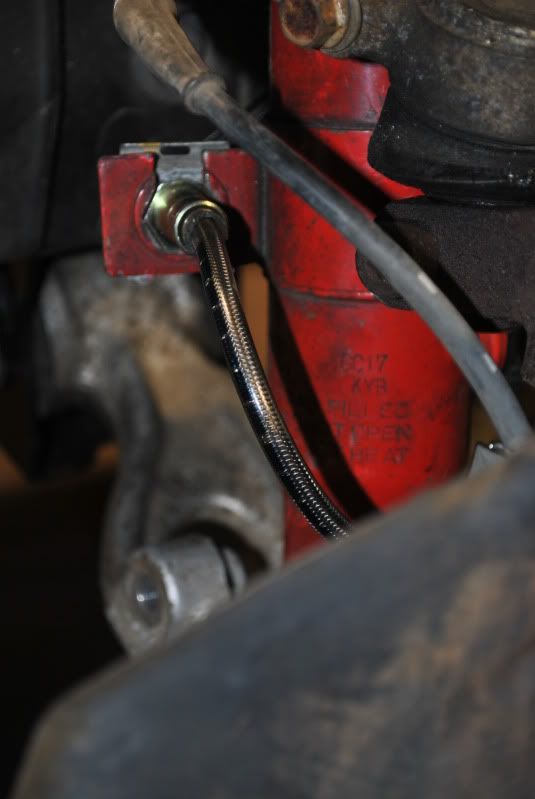
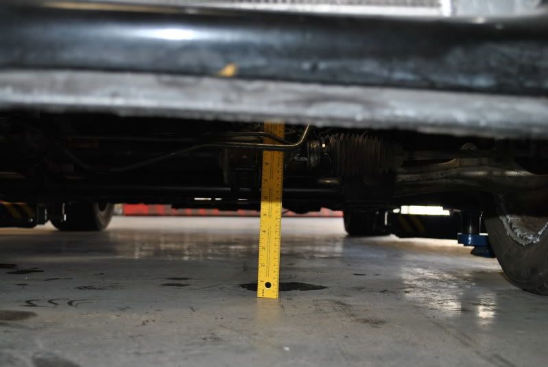
Shots of the smoked stainless steel brake lines to the calipers:
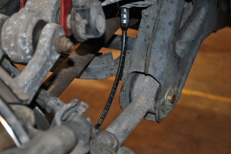
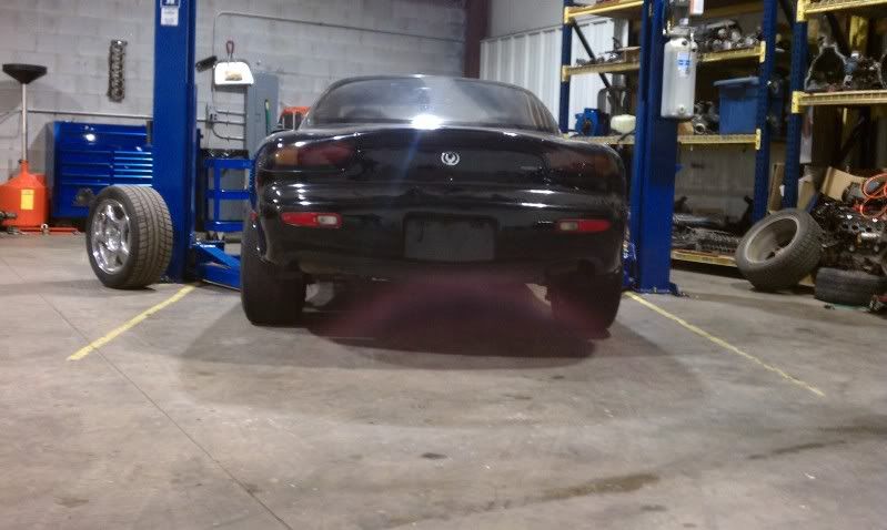
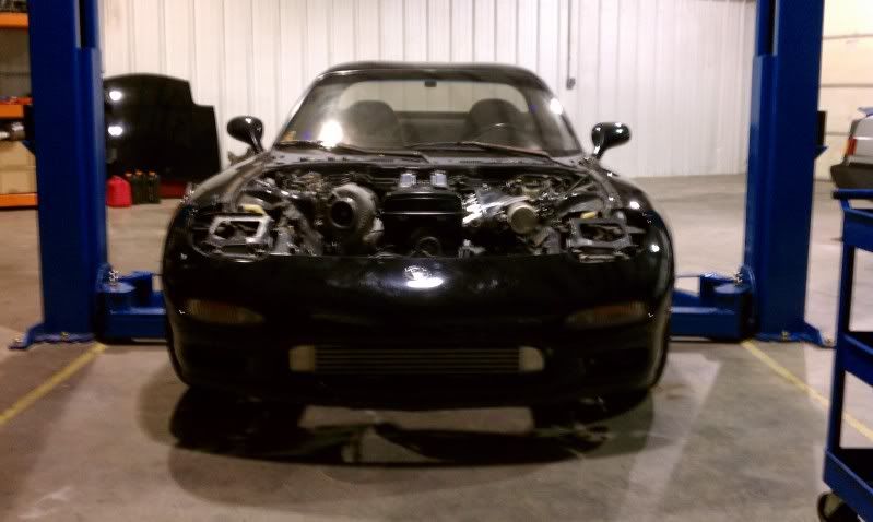
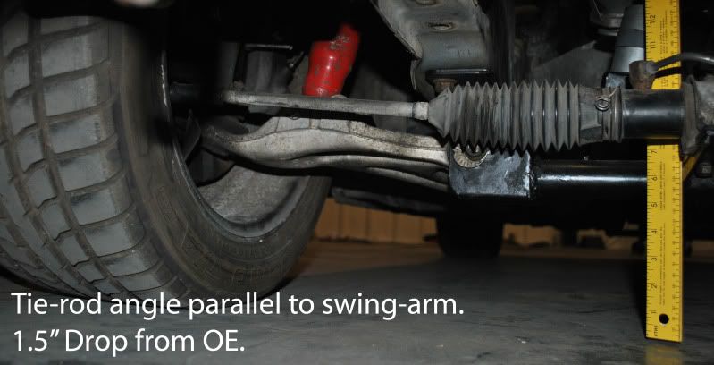
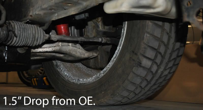
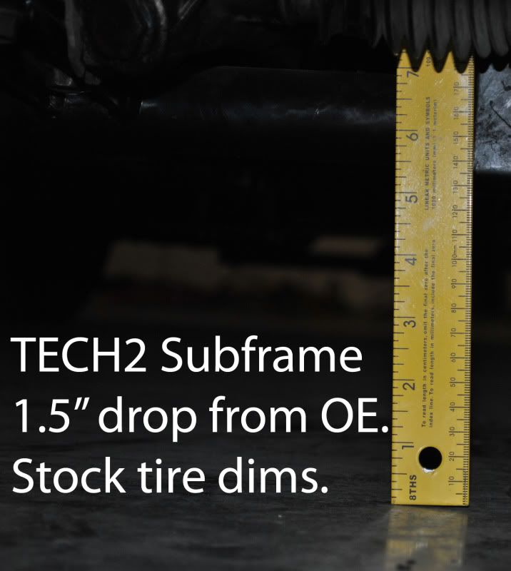
With the car lowered 1.5", the current subframe is 6" off the ground.
There is .25" clearance from the oil pan to steering rack.
The engine needs to move 2" down to clear the stock hood.
Thread Starter
Joined: Jul 2010
Posts: 499
Likes: 23
From: Greensboro, North Carolina
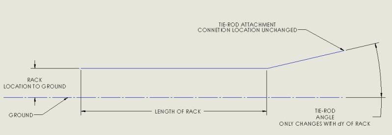
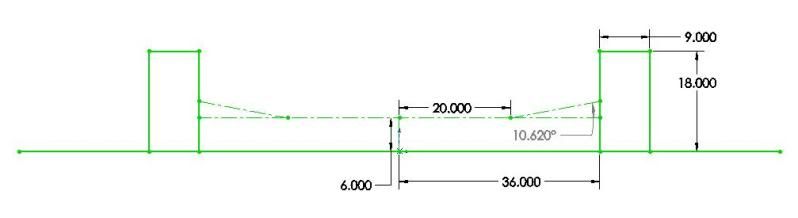
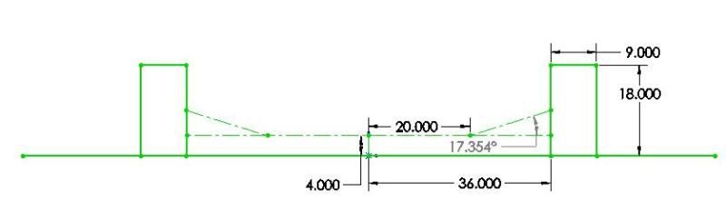
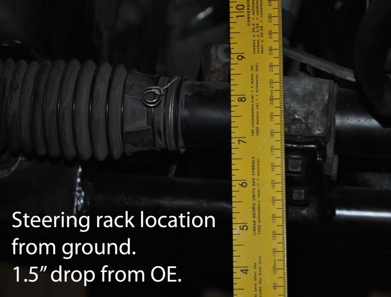
Using the numbers here just to describe the percentage in change of angle ONLY, you can see by reducing the steering rack's location results in a large change in tie-rod angle:
The illustration doesn't really represent the wheels, tires or rack, but rather the difference in angle required if you lowered the rack.
Note that everything is constant, minus the location of the line representing the rack to ground (this value is known and correct.)
As long as I keep the other arbitrary numbers constant, my angle difference can be calculated.
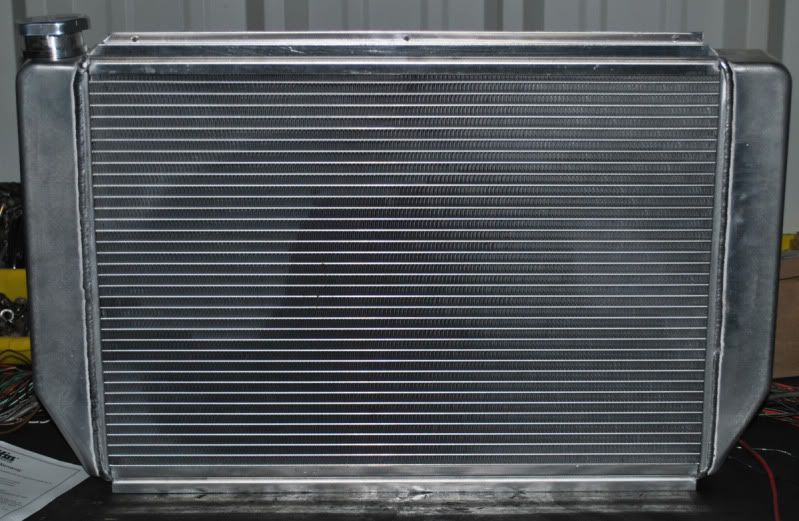
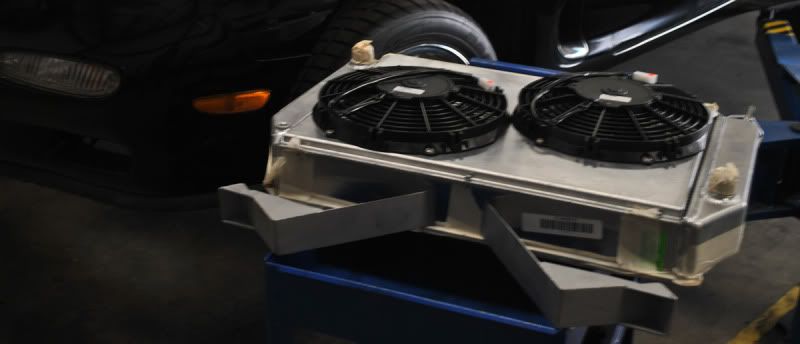
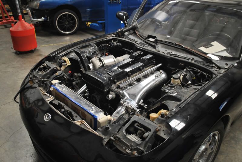
After making a rough model of a radiator, I ordered a custom one from Griffin:
Here are some pictures.
It's a 2.75" thick core 2-row.
-17AN fittings on feed and return that will go to fittings on my water necks.
Two electric fans and an aluminum shroud.
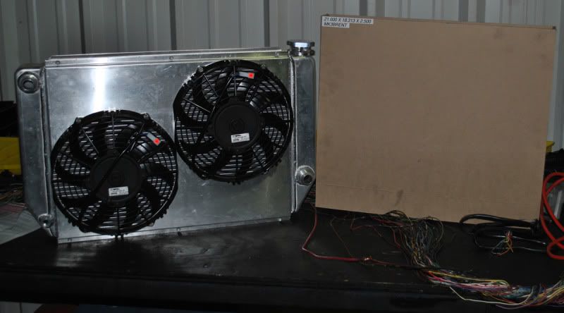
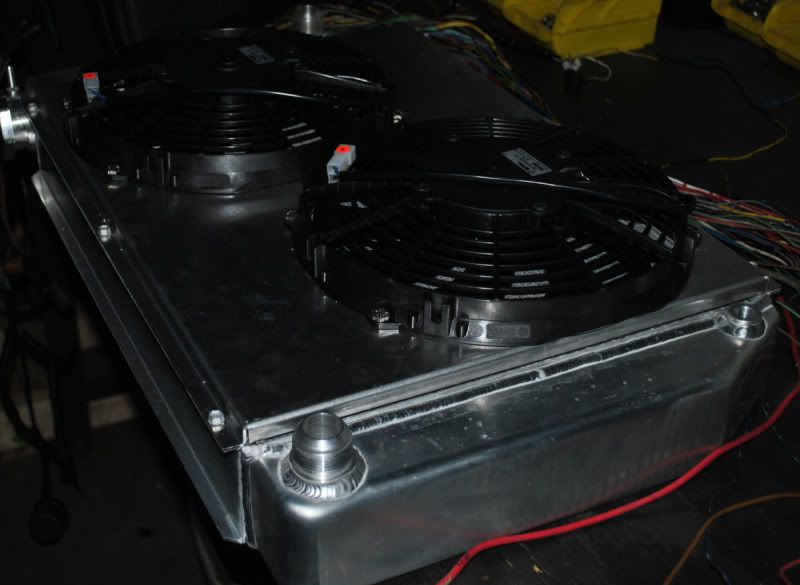
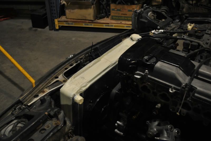
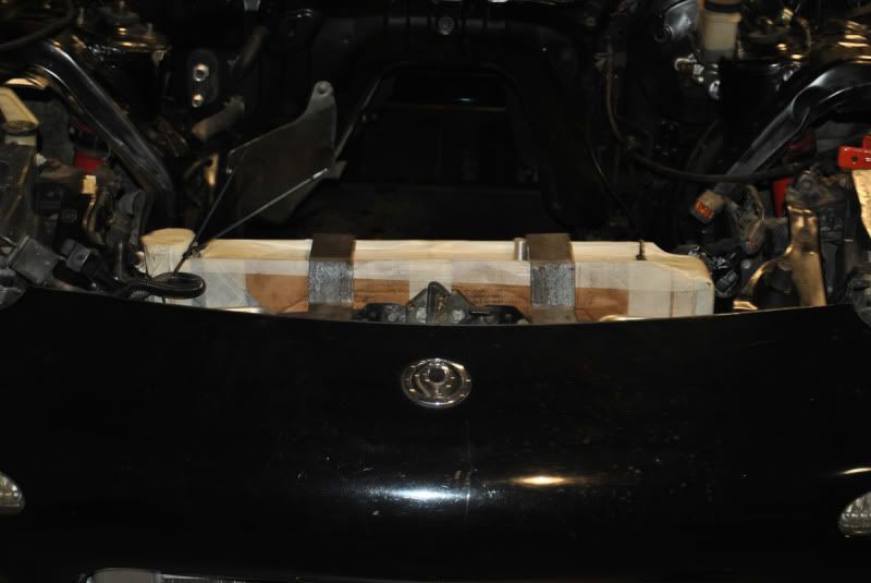
Wrapped the radiator up in some cardboard and masking tape so I wouldn't damage it while figuring out the position:
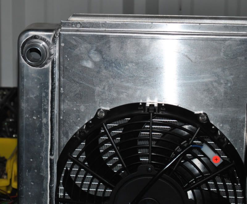
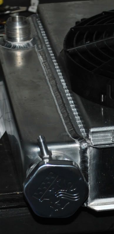
AN fitting facing the water neck:
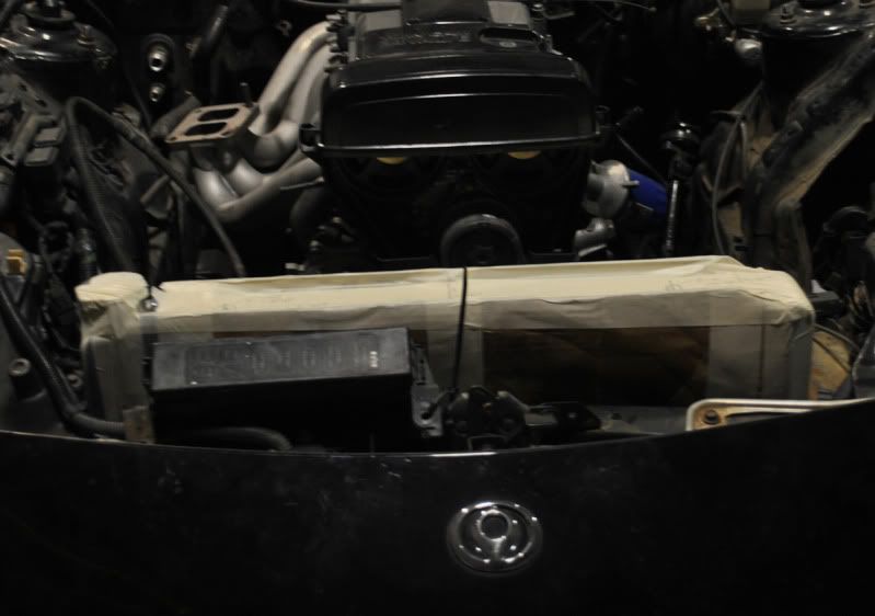
Expansion/overflow nipple is on the passenger side with a straight route to the stock bottle. Very clean, no hoses draping over the front of the engine bay.
The illustration doesn't really represent the wheels, tires or rack, but rather the difference in angle required if you lowered the rack.
Note that everything is constant, minus the location of the line representing the rack to ground (this value is known and correct.)
As long as I keep the other arbitrary numbers constant, my angle difference can be calculated.
After making a rough model of a radiator, I ordered a custom one from Griffin:
Here are some pictures.
It's a 2.75" thick core 2-row.
-17AN fittings on feed and return that will go to fittings on my water necks.
Two electric fans and an aluminum shroud.
Wrapped the radiator up in some cardboard and masking tape so I wouldn't damage it while figuring out the position:
AN fitting facing the water neck:
Expansion/overflow nipple is on the passenger side with a straight route to the stock bottle. Very clean, no hoses draping over the front of the engine bay.
Thread Starter
Joined: Jul 2010
Posts: 499
Likes: 23
From: Greensboro, North Carolina
Continued progress on radiator support design.
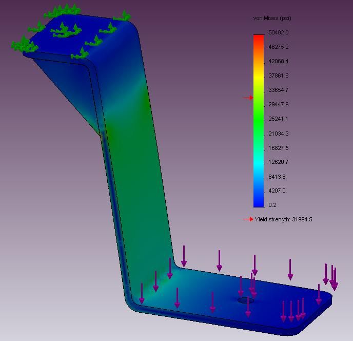
To validate the design in the system, I have simulated a static load of 100lbs on a radiator geometry to my bracket assemblies.
Assuming a total face to face bond in my gusset I get my results.
The stresses on the system are highlighted with the graph provided:
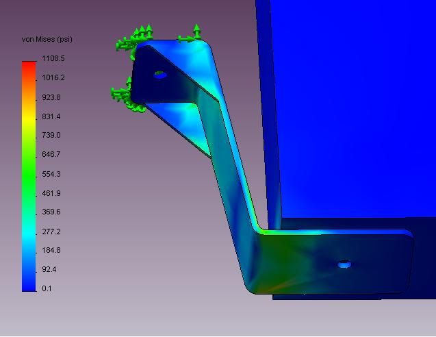
Here is a simulation of the yield strength of the bracket alone with 100lbs of force, notice the low value.
By calculating the yield strength of the bracket alone, we can determine it's functionality in the system. With the yield of the bracket in the 33ksi range, I am confident in the design seeing less than 700psi in the system:
Since I validated the design, I will now make the part:
Sheared out some AISI 304 steel and punched out some gussets:
I will attempt to weld them this weekend. Since it's been a while, I might just tack them and have them done professionally.
More to come.
Tacked up the brackets, etc.
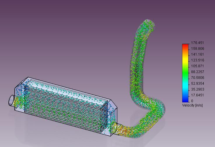
Using FloWorks simulation tool, I am able to calculate some air molecule trajectories through various environments. I modeled my intercooler, and core density to the published data provided to me by Spearco. The IC pipe geometry is subject to change at this stage:
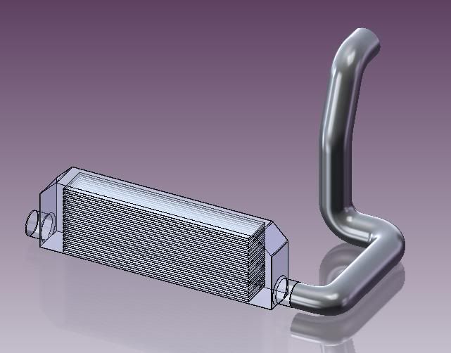
30PSI Environment without the intercooler core:
http://www.youtube.com/watch?v=6Zahg-lUraM
Last edited by MK3Brent; Jun 8, 2011 at 10:41 PM.
Thread Starter
Joined: Jul 2010
Posts: 499
Likes: 23
From: Greensboro, North Carolina
30PSI Environment with core:
http://www.youtube.com/watch?v=JxdqLZ7b8y8 The beginning of the vacuum line system:
Thanks to my friend at McMaster, I got these goodies in 8 hours.
Anodized vacuum manifold with 1/4 and 1/8 NPT taps so I can tuck and hide some air lines:
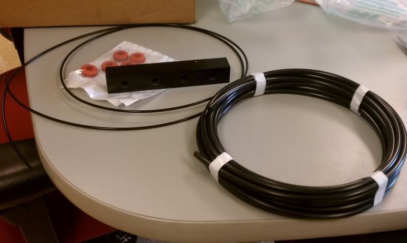

Sorting through some push-to-connect fittings.
At $47 a piece for the stainless steel ones, they're a real nice piece.

http://www.youtube.com/watch?v=JxdqLZ7b8y8 The beginning of the vacuum line system:
Thanks to my friend at McMaster, I got these goodies in 8 hours.
Anodized vacuum manifold with 1/4 and 1/8 NPT taps so I can tuck and hide some air lines:
Sorting through some push-to-connect fittings.
At $47 a piece for the stainless steel ones, they're a real nice piece.
Thread Starter
Joined: Jul 2010
Posts: 499
Likes: 23
From: Greensboro, North Carolina
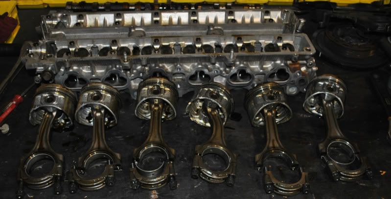
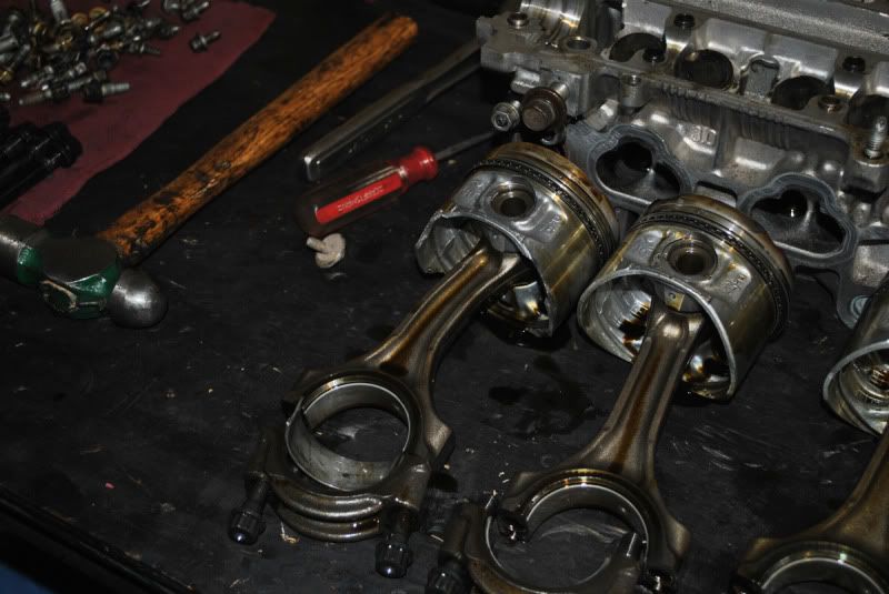
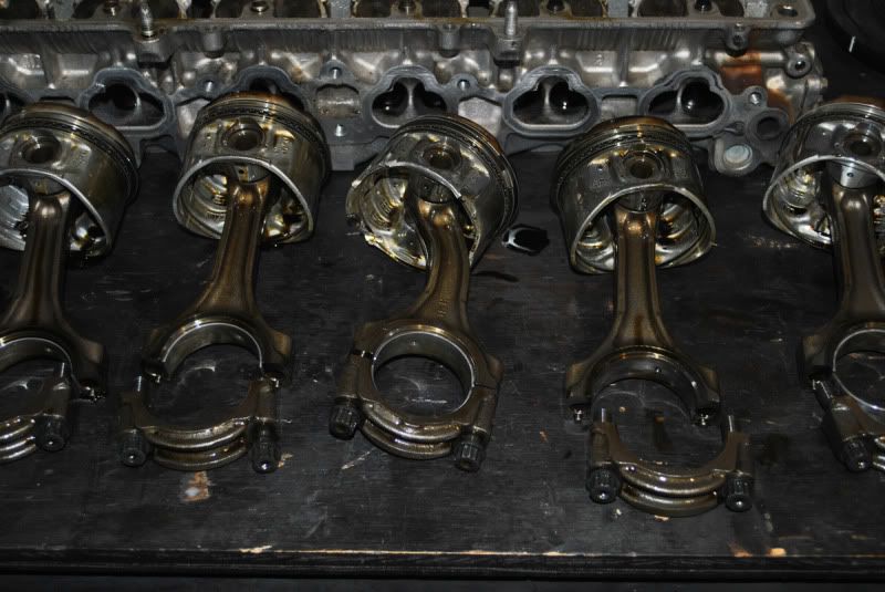
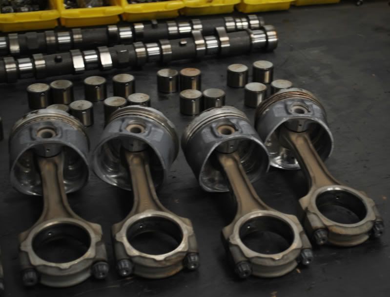
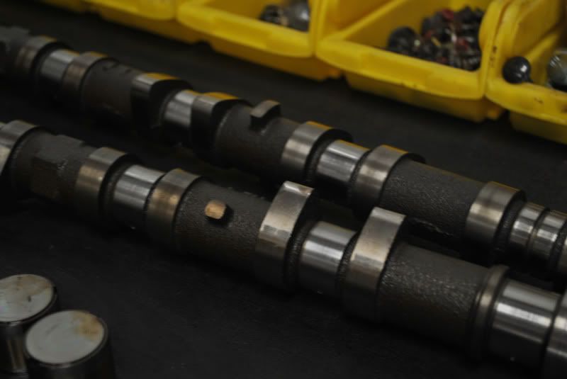
At this point it was discovered that my engine set was a blown up paper-weight.
Rebuild was in order... big time.
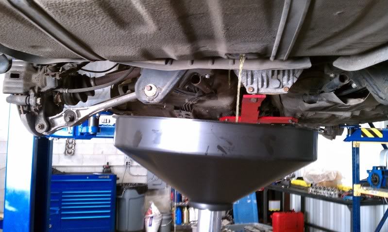
We decided to take the oil pan off of my 2J this weekend to replaced the nasty RTV silicone with some toyota FIPG.
Soon as we turn the engine over on the stand, we hear rattling...
Fearing the worst, we pull the oil pan to discover this...
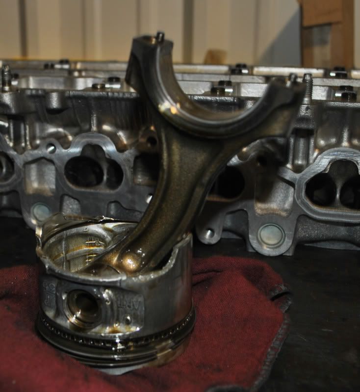
Rebuild was in order... big time.
We decided to take the oil pan off of my 2J this weekend to replaced the nasty RTV silicone with some toyota FIPG.
Soon as we turn the engine over on the stand, we hear rattling...
Fearing the worst, we pull the oil pan to discover this...
Thread Starter
Joined: Jul 2010
Posts: 499
Likes: 23
From: Greensboro, North Carolina
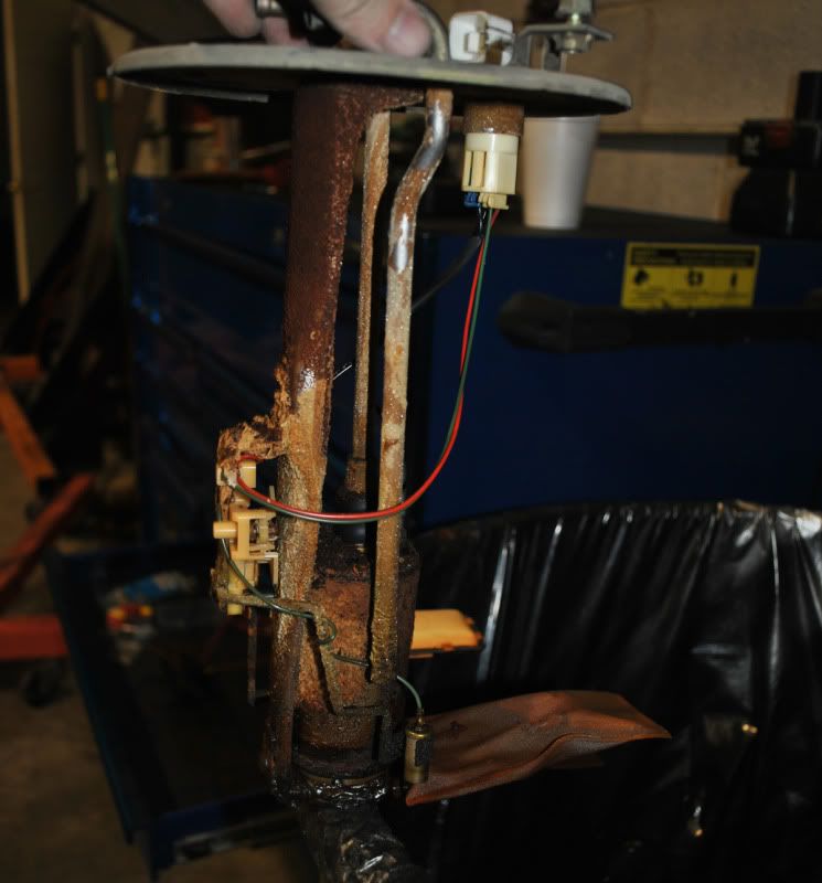
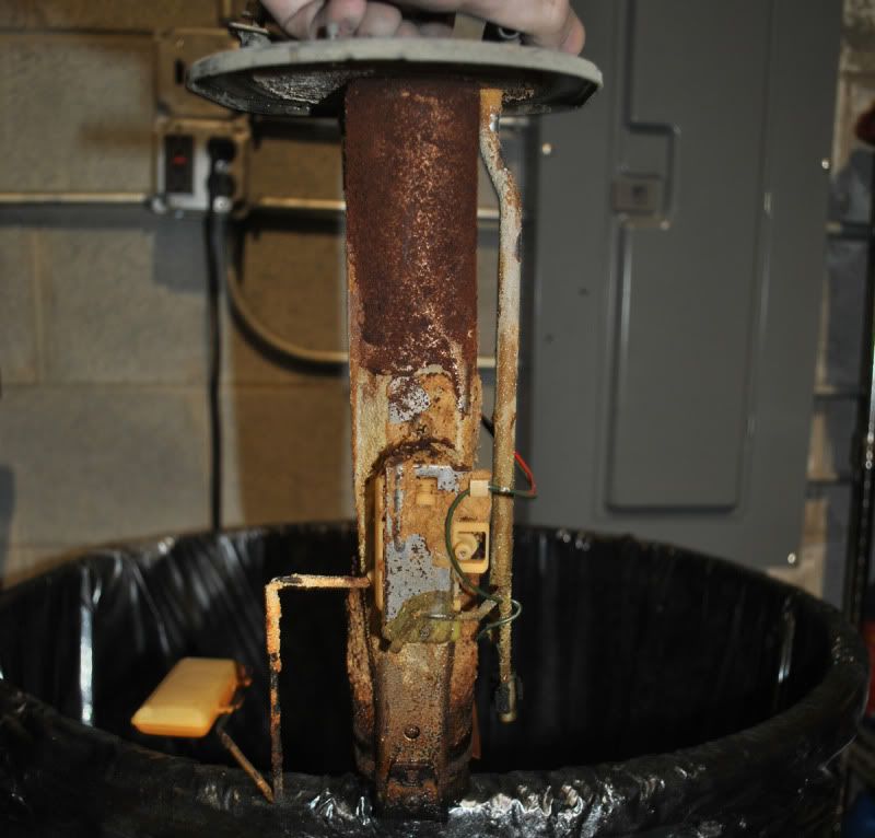
Fuel system overhaul!
Pulled out the stock fuel pump to get ready for the twin walboro 255's:
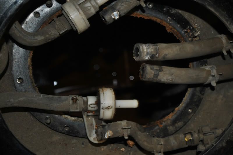
This pump should be good for about 8-1100 horses:
I didn't take any pictures of the new pumps.. everyone knows what they look like.
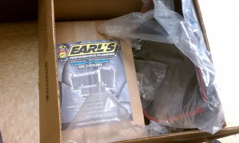
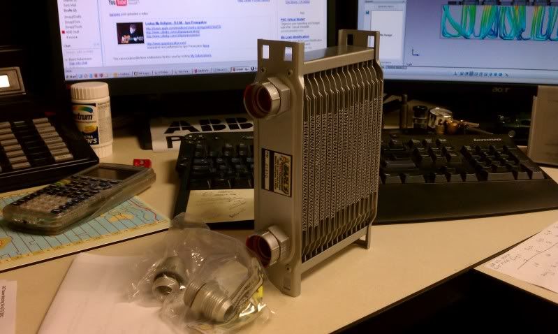
My Earl's oil cooler came in, and I started thinking about the position:
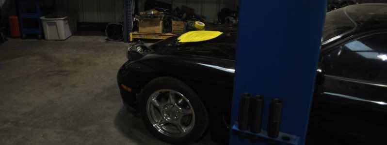
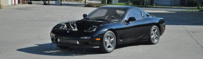
Here are also a couple sneak peeks at the hood modification.
Still going to require a lot more tweaking. :
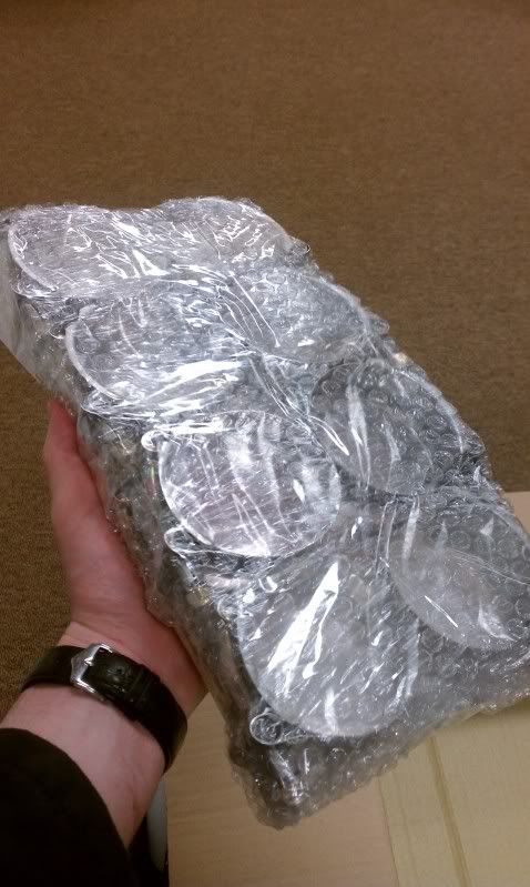
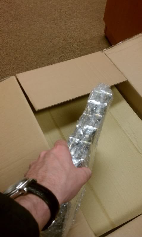
Ordered some different grommets I'm going to use, since I bumped up to a 5/8" aluminum stud.
Here are a couple pics from last weekend:
Pulled out the stock fuel pump to get ready for the twin walboro 255's:
This pump should be good for about 8-1100 horses:
I didn't take any pictures of the new pumps.. everyone knows what they look like.
My Earl's oil cooler came in, and I started thinking about the position:
Here are also a couple sneak peeks at the hood modification.
Still going to require a lot more tweaking. :
Ordered some different grommets I'm going to use, since I bumped up to a 5/8" aluminum stud.
Here are a couple pics from last weekend:
Thread Starter
Joined: Jul 2010
Posts: 499
Likes: 23
From: Greensboro, North Carolina

Thought I would post some numbers about things that could become helpful to anyone attempting this swap.
I'm not looking to start a business, or sell parts, or anything like that. I don't care.
I would just like to help anyone who could use it.
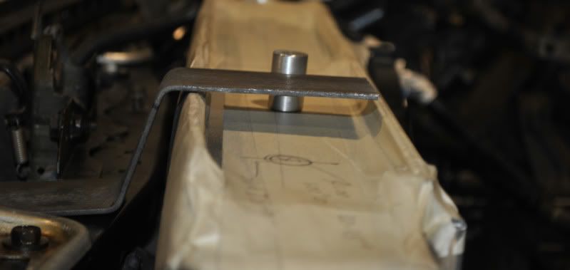
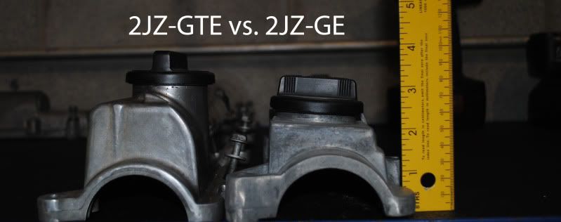
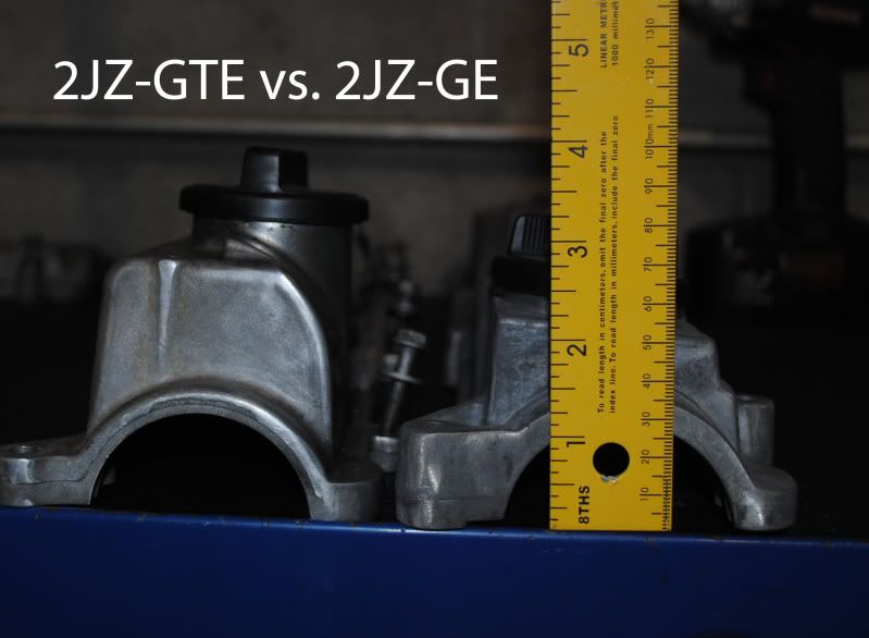
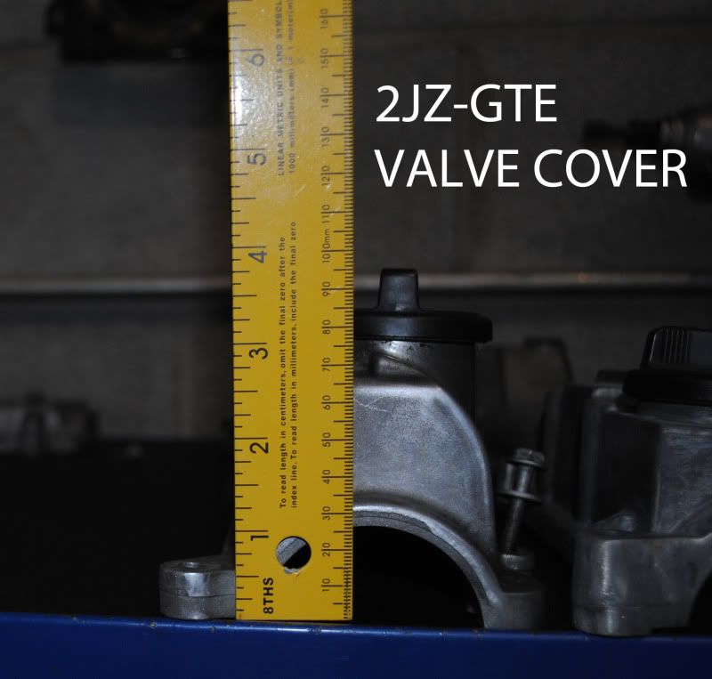
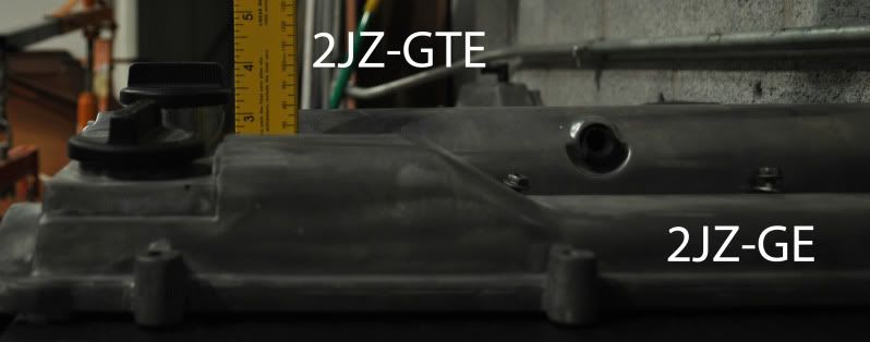
Here are some measurements of things like the subframe, tie rod angles, and 2JZ-GE components.
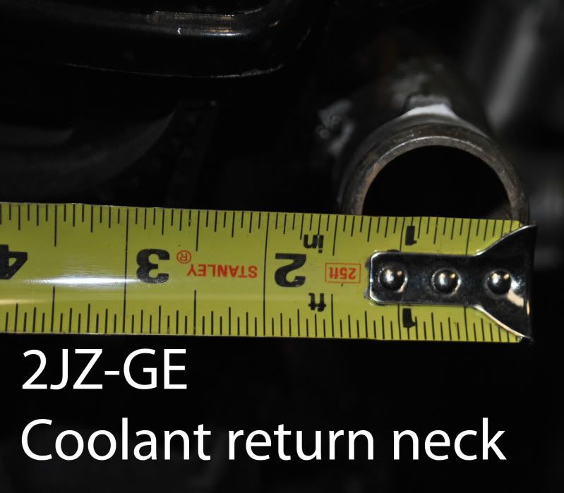
Here are some height differences in the GE vs GTE valve covers:
Thread Starter
Joined: Jul 2010
Posts: 499
Likes: 23
From: Greensboro, North Carolina
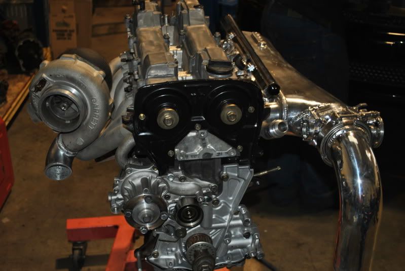
Fun stuff now:
Thanks be to CJ, my engine is all back together and ready to go.
Just sorting through the details left to get it all running.
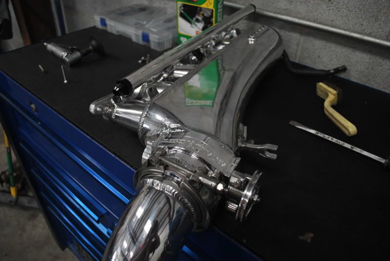
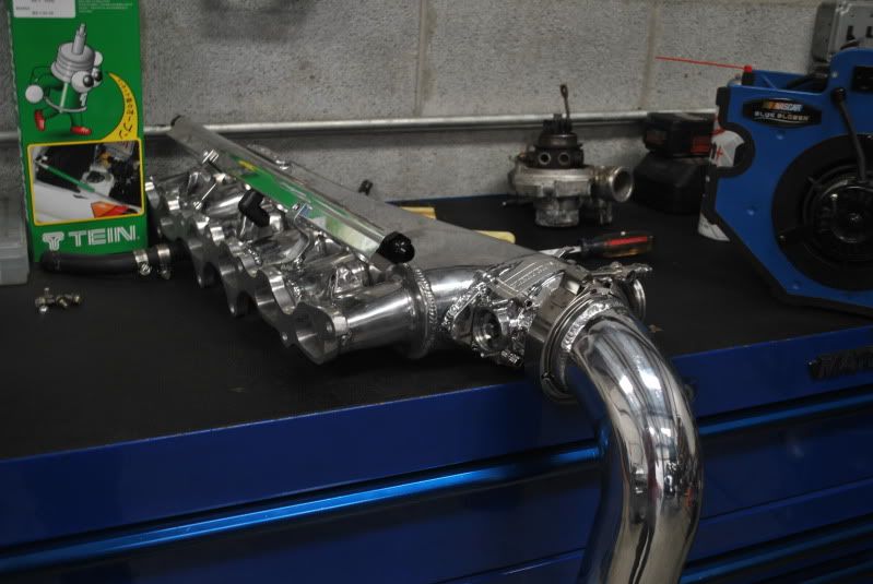
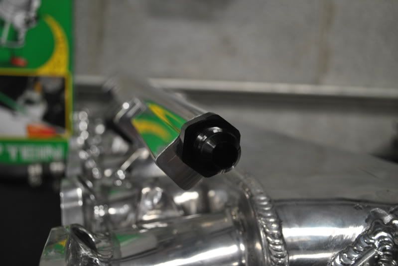
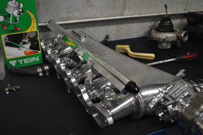
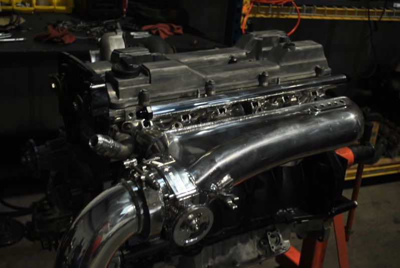
Got my manifold and throttlebody back from Seth.
The throttle body is a one off CNC'd 90mm made by Seth.
Check it out:

Thanks be to CJ, my engine is all back together and ready to go.
Just sorting through the details left to get it all running.
Got my manifold and throttlebody back from Seth.
The throttle body is a one off CNC'd 90mm made by Seth.
Check it out:
Thread Starter
Joined: Jul 2010
Posts: 499
Likes: 23
From: Greensboro, North Carolina
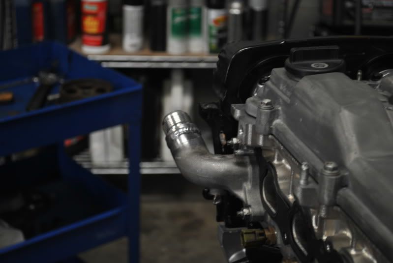
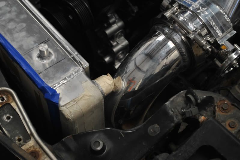
finished marking and fitting the grommets for the radiator as well as some new problems.
Going to have to modify the IC pipe by the TB perhaps to get the tight 90 degree fitting on the radiator.
There's just not enough clearance for both.
Anyway, here are a bunch of pictures.
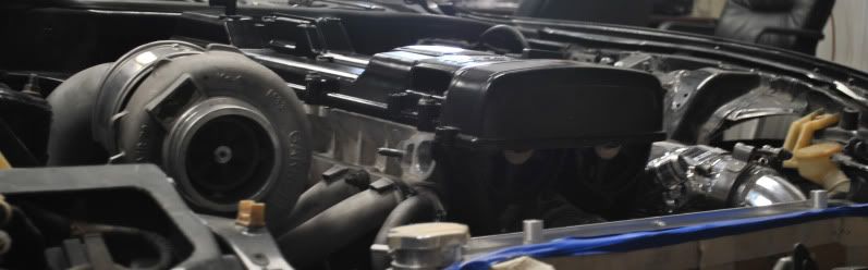
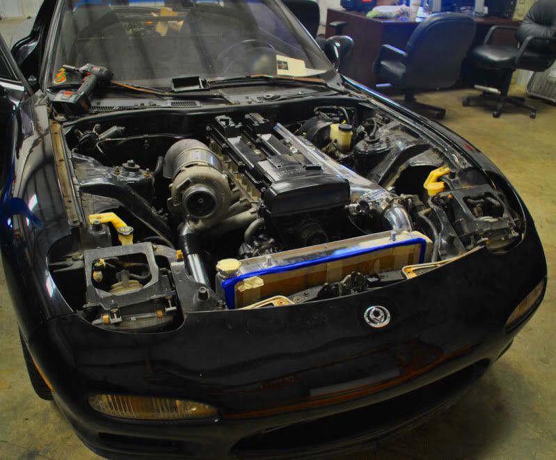
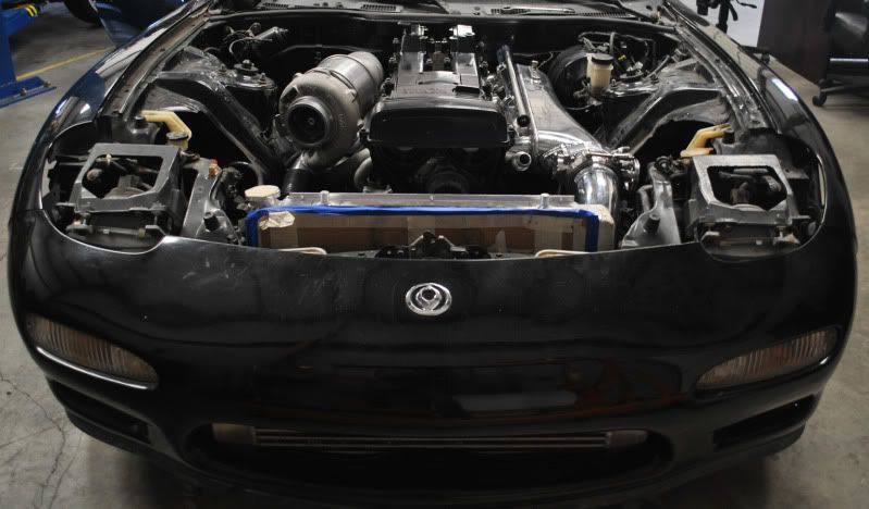
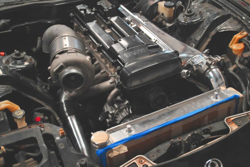
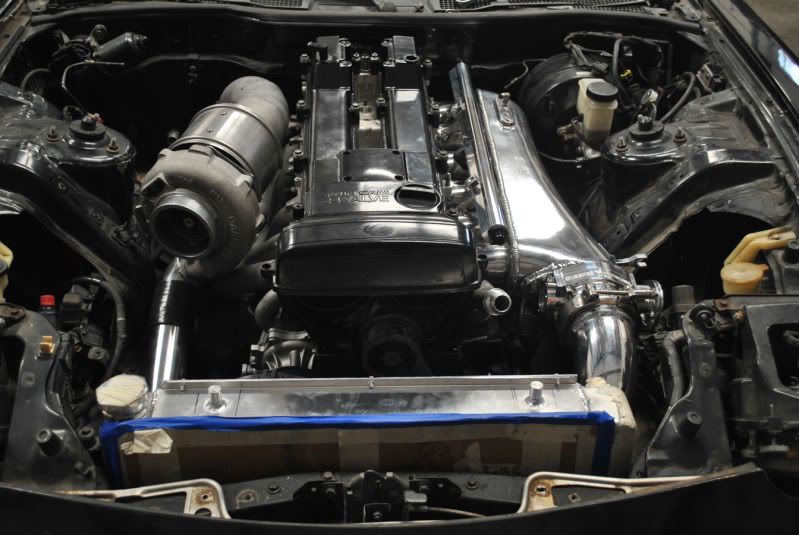
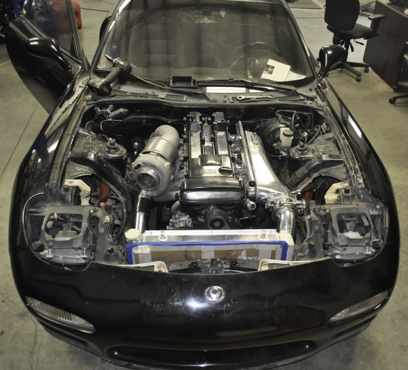
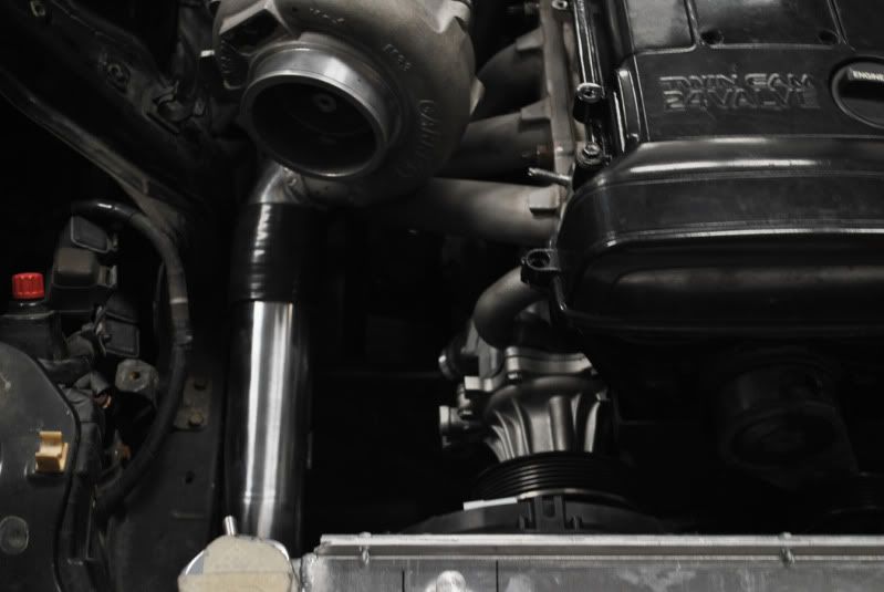
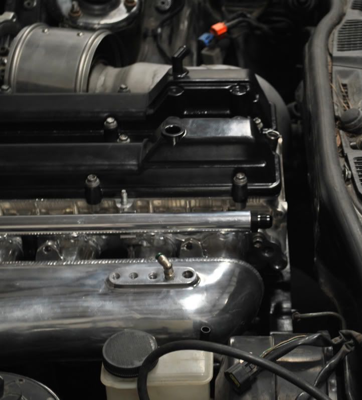
Clearance issues:
Going to have to modify the IC pipe by the TB perhaps to get the tight 90 degree fitting on the radiator.
There's just not enough clearance for both.
Anyway, here are a bunch of pictures.
Clearance issues: