
Little question for my transverse project


Thread Starter
Bart
Joined: Dec 2004
Posts: 78
Likes: 0
From: the Netherlands
Little question for my transverse project
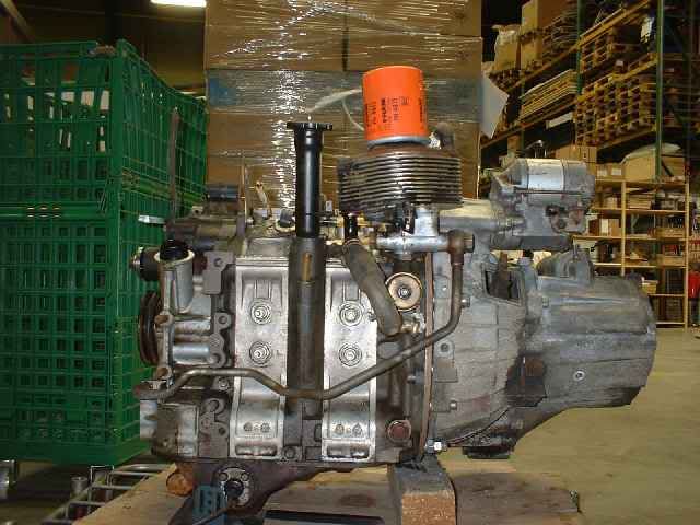
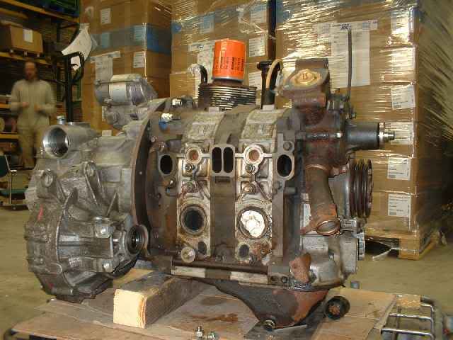
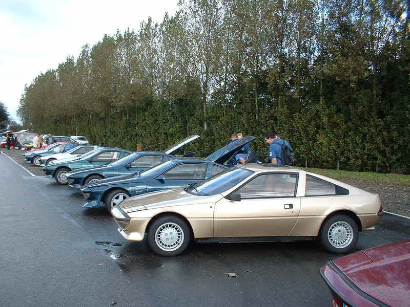
I am building a transverse setup using a 12A and a toyota transverse transmision. All this must power a 1981 matra murena which is a little french sportscar with the engine in the back. Much like a fiat X1/9.
Engine and transmision are connected, but there are still plenty problems to solve. The biggest is the driveshaft which runs alongside the engine.
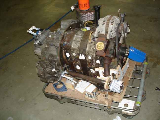
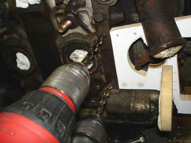
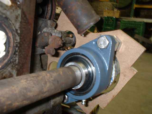
I have to make a bearing block for this driveshaft. It must be located very close to the oil outlets.
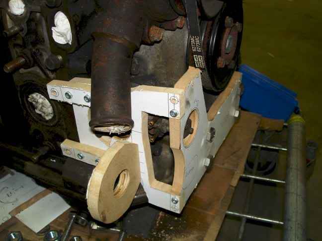
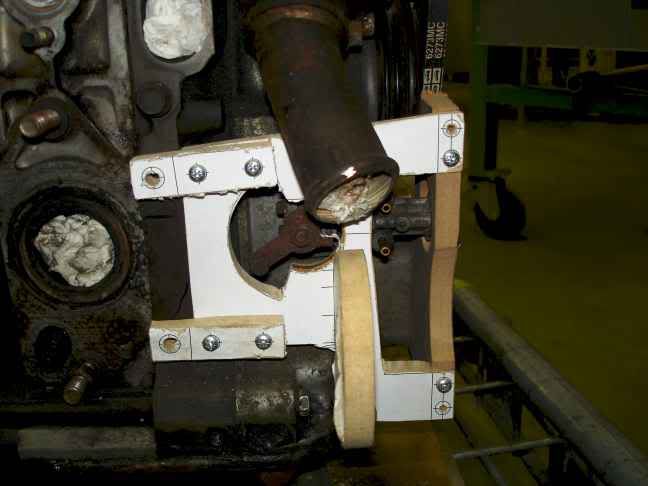
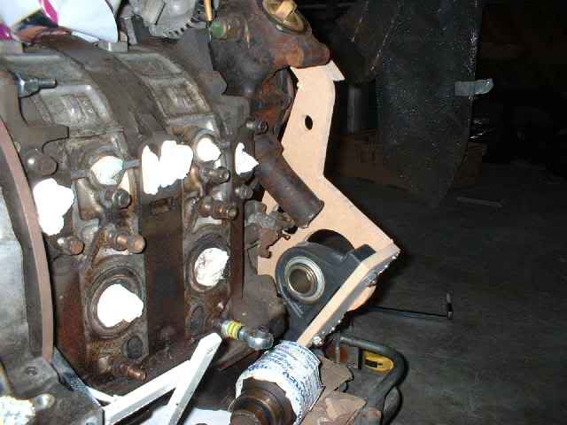
The plan is to make a bracket attached to the front engine mounts. This bracket runs to the side. At the end an other piece of steel is attached. This piece of steel will hold the bearingblock.
And here is my little question:
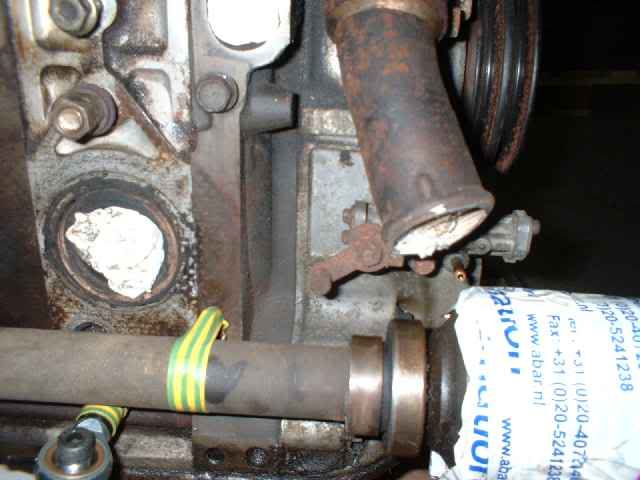
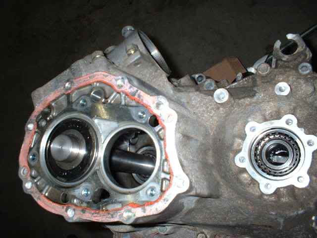
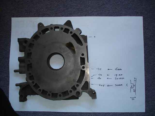
I want to mount the bracket to the front housing. Can make a treated hole here and here? Or will oil or water pour out?
Engine and transmision are connected, but there are still plenty problems to solve. The biggest is the driveshaft which runs alongside the engine.
I have to make a bearing block for this driveshaft. It must be located very close to the oil outlets.
The plan is to make a bracket attached to the front engine mounts. This bracket runs to the side. At the end an other piece of steel is attached. This piece of steel will hold the bearingblock.
And here is my little question:
I want to mount the bracket to the front housing. Can make a treated hole here and here? Or will oil or water pour out?
Joined: Oct 2003
Posts: 3,438
Likes: 6
From: Outskirts of Road Atlanta
Well, you're in the front iron there rather than the housing. It's almost dumb luck whether or not you'll hit the water jacket. You can go into the front cover, though, without doing any real damage. I'd go to a junkyard with a breaker bar, drop a 12A out of a 1st-Gen RX-7, get the front nut off, and take off the front cover to mess with. You can even pull the flywheel off and take out the tension bolts, and go home with the front iron. I wouldn't risk it on a functional, assembled block, though.
I went and measured my front cover. At where you want to put the top mounting bolt, you have just a little over 1/2 inch before hitting the water jacket. The bottom has just a small amount more. Don't know if this is enough for what you want to do. My guess is that if you are extremely careful you have a chance to make it work.
RXDad
RXDad
actually, the car frame should be the mounting point for this axle bearing, not the engine block. is there more to that axle that goes out to the wheel? when the engine torques up in the rubber mounting, that axle will move with it. not to mention what could happen once u tach it up and dump the clutch. not to put a damper on ur plans, but manufacturers don't mount drive axles to engines for a reason.
Last edited by rxtasy3; Mar 22, 2006 at 11:42 AM.
My FSP Fiesta eats Jettas
Joined: Aug 2002
Posts: 1,616
Likes: 3
Originally Posted by rxtasy3
actually, the car frame should be the mounting point for this axle bearing, not the engine block. is there more to that axle that goes out to the wheel? when the engine torques up in the rubber mounting, that axle will move with it. not to mention what could happen once u tach it up and dump the clutch. not to put a damper on ur plans, but manufacturers don't mount drive axles to engines for a reason.

Trending Topics
'Last Minute' Rallying
Joined: May 2002
Posts: 1,193
Likes: 0
From: Lincoln, England
Originally Posted by rxtasy3
actually, the car frame should be the mounting point for this axle bearing, not the engine block. is there more to that axle that goes out to the wheel? when the engine torques up in the rubber mounting, that axle will move with it. not to mention what could happen once u tach it up and dump the clutch. not to put a damper on ur plans, but manufacturers don't mount drive axles to engines for a reason.
yes they do, in fact a lot of Mazda fwd cars use nearly an identical system !
Take a look at Mazda protege with an 1800DOHC engine ... you will find the passenger side driveshaft has a bearing on it already (bolted to the block)
Thread Starter
Bart
Joined: Dec 2004
Posts: 78
Likes: 0
From: the Netherlands
Thanks guys, I'll go the safest way and find me an front iron. There are not much rx-7's her to find on scrapyards, but i'll find one.
Drilling in the front iron seems to be more tricky then i thought, but it is nescessary to get a solid mount for the bearing.
I am very curious how others have done it on there FWD honda civic or 323.
Drilling in the front iron seems to be more tricky then i thought, but it is nescessary to get a solid mount for the bearing.
I am very curious how others have done it on there FWD honda civic or 323.

Senior Member
Joined: Jul 2003
Posts: 416
Likes: 0
From: Wayne, NJ 07470
Cool.
How did you adapt the transmission to the engine?
Is the thickness of the adaptor plate a significant consideration when mating the transmission input shaft to the flywheel? And also the starter motor?
Which clutch and flywheel will you use? Can you get away with just an Rx7 flywheel and pressure plate with a Toyota clutch disk? Would the Toyota starter motor work with an Rx7 flywheel?
The MR2 transmission is supposed to be the same as the Solara except the shift linkage is moved to the front of the engine. Do you think running cables to the shift linkage on the back will be difficult to set up? Or will you drill the transmission and move the linkage to the front? A few people on the MR2 forum have used the Solara trans in the MR2 with this mod but I don't know how difficult it is.
For the driveshaft bearing, one alternative to drilling holes in the engine might be to extend the transmission adaptor plate and create a framework around the engine to the front engine mount.
Good luck
(try to get more ambient light and less flash if you post more pictures)
My FSP Fiesta eats Jettas
Joined: Aug 2002
Posts: 1,616
Likes: 3
Originally Posted by Crit
Well yeah, but that's just powering a Radio Flyer. I doubt it's indicative of how a car manufacturer would do it...
I actually had a "rotary wagon" emblem from an RX4 wagon that I was going to mount on it, but I ended up selling it for like $45 on eBay.
That's a Fiesta motor that was turbocharged BTW.

Thread Starter
Bart
Joined: Dec 2004
Posts: 78
Likes: 0
From: the Netherlands
Originally Posted by Wankelguy
Oh, and why not just weld a bolt to the header flange for the upper mounting point?
Originally Posted by edmcguirk
How did you adapt the transmission to the engine?
The 12A (manual gear) flywheel is pretty big. To big to fit in the original bellhousing of my car. The toyota gearbox has a big bellhousing.
I didn't want to do it with a counterweight of a automatic 12A and fit an other flywheel. These counterweights are rare in europe and i cannot do the machining of the flywheel myself. I don't want to spent any money at this project as long i'm not sure it will succeed.
I have used 12mm steel as a adapter plate. It sounds a bit heavy, but it is not that bad. I prefer steel over aluminium because i have moer faith in treathed holes in steel instead of alu.
The input shaft of the transmission doesn't have a center axle. So that's a worry less. The inputshaft is cut a little shorter (just a few mm) but it might be not nescesarry. I shortend it because i first planned to do a 8mm adapterplate. With a 12mm adapterplate cutting might be not nescesarry.
The best thing about the toyota tranny is the starter motor. Most other transverse engine's have the startermotor alongside the engine. But the toyota
has the starter on top of the tranny. The sprocket of the toyota seems to match the 12A flywheel. The position of the starter needs to move a few mm outward and away from the engine.
I use the 12A pressureplate with a toyota clutch disk.
That is a cool car!
On to your question: if you get into the water jacket when you drill, it's not the end of the world. On this side of the pond, the 4.0 Jeep 6 cylinder needs sealant on one head bolt because it goes into the water jacket, and the older 302 (5.0 l) Ford V8's needed the same thing on some the exhaust manifold bolts. There are other examples as well, those are just two of the most common ones.
If you drill and tap a hole in the iron and hit water, I suggest using a stud rather than a bolt, with something like Loctite on the threads to seal it.
Someone mentioned using the exhaust studs. I'd want to avoid this, as the exhaust studs go into aluminum and torquing them tight enough to keep the plate from moving could conceiveably pull the threads out of the housing, as that's not the job they were intended for.
You mention the Toyota transaxle has no 'center bearing', what I take to mean no 'pilot bearing' to center the input shaft in the flywheel. Out of curiosity: how are you centering the transmission to the eccentric shaft?
Last edited by RX744CSP; Mar 25, 2006 at 09:17 PM.
Thread Starter
Bart
Joined: Dec 2004
Posts: 78
Likes: 0
From: the Netherlands
Originally Posted by RX744CSP
the 4.0 Jeep 6 cylinder needs sealant on one head bolt because it goes into the water jacket
Originally Posted by RX744CSP
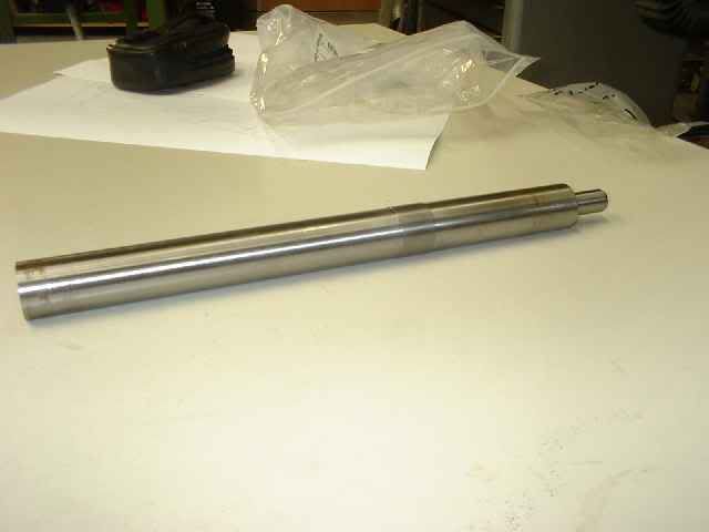
You mention the Toyota transaxle has no 'center bearing', what I take to mean no 'pilot bearing' to center the input shaft in the flywheel. Out of curiosity: how are you centering the transmission to the eccentric shaft?
The transmission is dismanteld. I had a shaft made as a center tool. The shaft comes in place of the input shaft. It has a pilot pin (is that the right word?)
My FSP Fiesta eats Jettas
Joined: Aug 2002
Posts: 1,616
Likes: 3
Originally Posted by RX744CSP
Someone mentioned using the exhaust studs. I'd want to avoid this, as the exhaust studs go into aluminum and torquing them tight enough to keep the plate from moving could conceiveably pull the threads out of the housing, as that's not the job they were intended for.
Thread Starter
Bart
Joined: Dec 2004
Posts: 78
Likes: 0
From: the Netherlands
I just get my hands on a brand new front iron. It's a pity but it will be sacrified for sience. The metal outside is beefy enough to make treathed holes in.
Shortly i start making the final drawings for bearingmount, adapter plate, engine mounts, and other bits. these will be made on a waterjet cutter. I also making (a few) new header flanges. I noticed on the old headerflange that the surface is deepend around the gasket. Can i use a flat surface flange instead? And does these flanges have to be that beefy?
Shortly i start making the final drawings for bearingmount, adapter plate, engine mounts, and other bits. these will be made on a waterjet cutter. I also making (a few) new header flanges. I noticed on the old headerflange that the surface is deepend around the gasket. Can i use a flat surface flange instead? And does these flanges have to be that beefy?
Senior Member
Joined: Jul 2003
Posts: 416
Likes: 0
From: Wayne, NJ 07470
I just came across this and even though it would be heavier, I think it would be a better solution.
http://www.rotaryaviation.com/engine_mounts.htm
http://www.rotaryaviation.com/RV8Project.htm
http://www.rotaryaviation.com/engine_mounts.htm
http://www.rotaryaviation.com/RV8Project.htm
The header flange has to be really thick, since there is such a long distance between the header mounting studs. Any thinner, and it would be prone to warpage (rotary exhaust is REALLY hot!).
That aviation mount is nicely designed, but I think it would be overkill for this project.
That aviation mount is nicely designed, but I think it would be overkill for this project.
Thread Starter
Bart
Joined: Dec 2004
Posts: 78
Likes: 0
From: the Netherlands
The mount for the drive shaft bearing is sorted. Making threated holes in the front iron is no problem.
The header flange which was on the 12A was 14 mm (0,55 inch) thick. I wonder if a 12 mm (0,47 inch) is too thin. I get the adapterplate and several brackets / mounts from a 12 mm steel sheet cut by waterjet. I can add the header flanges with no extra costs.
The header flange which was on the 12A was 14 mm (0,55 inch) thick. I wonder if a 12 mm (0,47 inch) is too thin. I get the adapterplate and several brackets / mounts from a 12 mm steel sheet cut by waterjet. I can add the header flanges with no extra costs.
Originally Posted by eatmyclutch
What are these?
Originally Posted by bart_heemskerk
I am building a transverse setup using a 12A and a toyota transverse transmision. All this must power a 1981 matra murena which is a little french sportscar with the engine in the back. Much like a fiat X1/9.