When you click on links to various merchants on this site and make a purchase, this can result in this site earning a commission. Affiliate programs and affiliations include, but are not limited to, the eBay Partner Network.
Right first off who, what and why... i purchased an rx7 FD3s twin turbo 1993 automatic about 8 months ago and upon test driving i soon noticed the car didn't perform very well despite the owner having receipts for work done, including an engine rebuild and a rats nest refresh using silicone hoses. Anyway the first job was to ditch the auto box and soon ill make a write up on this as well as there is a lot of information out there on how to do this but its not all in the same place and easy to get hold of a bit like the rats nest guides. So i installed the manual box and diff and got the car running and soon realised the car was loosing boost on the change over which is about 4k rpm however this was less noticeable on the auto box as the car would change gear at 6k rpm so although i noticed the boost drop it wasn't as nearly as noticeable as the manual gearbox which struggled to pull after 6k RPM. After much research about this that and the other i decided to buy an Apexi ECU as it would help me tune the car up and run better and also diagnose electronical faults as that was my first port of call. I will add that i usually build my own ECU's using megasquirt as i tune and map engines and i have built several customised engines with turbos and supercharges using the megasquirt and for me its a better system to use as you can tailor everything on the car but that's another story....
Anyway back to the task at hand, i knew the turbos was loosing boost after the change over but not before and the boost gauge was registering 14 PSI up to the change over so i know there are no boost leaks in the system and that there must be a problem in the rats nest or one of the actuators. I did find upon investigation that the turbo control actuator was faulty and leaking boost on the pressure side and so i replaced it with another second hand one! however you can purchase a twin port solenoid as an aftermarket one which will do the job and it is rebuild able but for now we will stick with the standard system.
Ok so here it is the rats nest guide, not for the faint hearted, this took me 3 weeks on and off tearing it down and working out exactly how each system in place is used to control the actuators and what order they work in to make the twins work correctly. I phoned a few rotary specialists in the UK and most of which said it could take them weeks to find the fault and that its a 20 year old car and it will never work as good as it did when it came out of the factory so we usually single turbo convert them or simplifiy sequential the system... Well this is total horse crap if i wanted a single turbo car or simplified seq turbo car id stick with the subaru wrx i got or the mx5 supercharged which i built! i want my car to work as it did out the factory and i will not stop until i got it 100% !!! and thats exactly what i did !!! the whole point of the twin charged system is to give you seamless smooth power from start to finnish not loads of lag until 4k RPM to red line !! So basically i had no previous history of RX7's whatsoever and my FD never boosted after 4k so the moral of the story is, if i can do it you can do it and to help you here is hopefully a guide on how to do that to help you with your project and hopefully my 3 week headache will now take you less than a day to do so my hard work will be your gain lol.
Here is a guide to the rats nest problem on an RX7 FD3s, as far as i am aware even the new ones with the all in one
black box on the later 98 FD's still work on the same principle and you can still create a relocation nest the way i have.
I have taken some of the original diagrams found on this forum and the FSM and modified them to make it easyier to work with as they dont really make a lot of sense or make it clear as to how they work or function. I have made a few diagrams of my own to help illistrate how the system works and what they do under different conditions.
The Rats nest has been broken down in to segmented colours to make it easier to understand and follow.
The twin turbo system and the fuel rail pressure are the only ones required on an aftermarket ecu as the other controls are for emmissions only, however removing the AWS system will mean the car will not pass emmissions during an mot where as the charcole canister can be removed if you want, i did this to make more space and tidy up a bit.
The double throttle control has many people confused as to what its operation is and what its purpose is so ill try and clear that up for you here. In a nutshell its used only on the warm up cycle to improve idle stabillity and reduce over reving when the engine is cold, once the engine has compleated its warm up cycle it is no longer used and it is deactivated, you can of course compleatly remove the system or jam the flaps permanently open but of course on a standard ecu this will throw up a check light.
You dont need really expensive equipment to test the system, all you need is a cheap vacuum and pressure tester, i got mine on ebay and it does both for 20 quid!!! Id also invest in some new check valves as you may as well replace these as you have the system in pieces, you will need at least 6 rated at 15 PSI this will ensure no leak backs on the relevant pipes.
You will need if you want to relocate the rats nest about 6 T Piece connectors and you will also need some silicone piping if you are to replace the rubber pipes that brake or go brittle, the internal diametre is 4mm and you will need about 14 metres for a relocation or 4 - 6 metres for an original rats nest refresh.
Ok so why the relocation ? basically your engine gets hot and with heat things perish and break down and your probably going to find that all the hoses on the nest are brittle and are more like plastic than rubber. the control solenoids can stick open when they are too hot causing operational problems, there are test procedures which i will talk about later. You do not need to relocate the nest you can just relace the rubber pipes with silicone and still follow this tutorial as it covers all of , i decided to move it as it makes diagnostics easier to do and servicing which is explained later.
To remove pipes use a pair of good pliers and twist the pipes ends first to break the seal and then twist and pull to release. The new silicone hoses will not need glueing or clamping on the pipes as they will self grip on to the pipes under vacuum and heat from the engine .
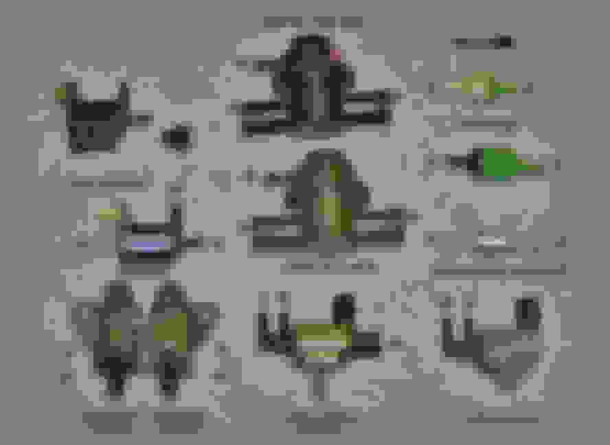
Picture of the check valves and solenoids:
The solenoids have 3 ports labled A, B and C
A = Source port
B = Output port
C = Dump port
Activated C = closed, A open to B
Deactivated A = Closed, C open to B
A is usually connected to a vacuum or pressure source.
B is usually sent towards an actuator.
Unless an normally open logic is required then C is used as a source and A is dump.
Said another way, each solenoid has a source port ("A"), a dump port ("C"), and an output port ("B"). When not energized, the solenoid shuts off A and sends C to B. When energized, the solenoid shuts off port C and directs port A (usually connected to vacuum or pressure source) through port B. The output B is usually sent toward an actuator, the source is either the pressure or vacuum tank, and the dump port is usually sent to atmosphere. In a few cases when a normally open logic is required, C is used as the source and A is dump.
Before we get down and dirty with the rats nest first we need to check all the solenoids that control flaps on the system for leaks and malfunctions.
All the actuators work by moving a plunger that controls a flap to open or close, some 2 port actuators will use either vacuum or pressure to move the flap or 3 ports to use vacuum and pressure to move the flap, twin port actuators are more efficient as they reduce spiking in movement due to differential pressures or boost spiking to put it another way.
First a nice and easy one to check is the double throttle control actuator..
Using a vacuum tester apply vacuum and check for leaks, using the vacuum tester get around 50 hh mg and you should notice that the rod pulls shut and holds shut, if it moves after a few minutes there is a problem with the solenoid and it needs replacing !.
Right hopefully you have a feel of how to do the checks so now we need to move on to the next actuators to test for functionality.
The next easy one is the factory BOV which is located on the Y Pipe and it is used to bleed of pressure from the second turbo when it is trying to match the speed of the primary turbo. You will note the arrow on the actuator shows the flow of air in normal operation. With no vacuum applied use a pressure tester to see if leaks occur, you should apply 13 PSI of pressure to the input and see no leaks on the gauge what so ever, if it leaks bin it ! if it doesn't then apply vacuum to the top of the BOV and blow through the actuator to make sure air flow through it . If it doesn't bin it ! and again you can apply the same test to the Recirculating valve thats in the middle of the Y Pipe! it is also worth noting that if you have replaced these with dump valves and diverter valves like i have the same test still applies because they are still doing the same job and if they leak they are no good ! dump valves should not vent on idle they should be closed because the system is not under enough pressure !.
Ok good so you have tested the BOV and now there is only a few more left, we will start with the charge control flap which is also located on the Y Pipe. This is designed to be closed until both turbos are ready to work together then the flap will open allowing the second turbo to boost with the first turbo. The reason for this is that if the flap didn't exist then the primary turbo will be sending air in to the second turbo which will stall the turbo and produce no boost as air is a lot like water, it will find the easiest path and follow it, in this case the second turbo is a lot closer that the intake chamber on the manifold so hence the flaps installed.
To test the flap apply vacuum to the top nipple, this is the vacuum side and check for leaks, you should see the control arm move in. If it doesn't bin it !, if it works then apply pressure to the bottom side of the actuator which is the pressure side and check for leaks and movements of the rod, if it doesn't bin it !. So why vacuum and pressure on the same control actuator ??? well basically what happens here is the positive boost pressure from the second turbo will apply no pressure until it is told to spool up around 4k RPM and so the vacuum side will pull the flap shut until it is needed, however how will the system know when the second turbo has matched the primary turbo in speed and pressure ?? well the answer is simple, as the pressure increases on the back of the actuator for the charge control equal / greater pressure will come from the vacuum side as this is changed from vacuum to pressure as the turbos change over occurs from the solenoids that control the actuators, when this happens the flap will open, so you can see that when the pressures from the two different turbo sources meet the flap will open as the pressure equalises.
Right so we are now ready to check the next two actuators, the Wastegate actuator and Turbo Pre-Control actuator. These both work exactly the same way so the test procedure is the same. They both have two ports on the actuator but there not separated, one end is connected to a vacuum source and the other a pressure source, the principle is easy, when pressure is applied from the primary turbo it is fed in to the actuator and passed to the vacuum side of the system via a control solenoid, when this solenoid is shut it will force the pressure to go back to the actuator which will force the piston open actuating the actuator !, so to test this we need to cap one side and apply pressure to the actuator 13PSI no more as this will damage the actuator ! the rod should move out and stop and not move back in due to a leak, if it leaks bin it !.
And finally the Turbo control actuator, this has two seperate chambers like the charge control actuator, pressure is fed in one side and vacuum on the other so like the charge control the top nipple is vacuum and the side nipple is pressure test accordingly and if it leaks ditch it and replace!!! remember a leak in any of these will cause a total system failure !!!!.
Ok so now we are happy with the actuators we need to test the vacuum chamber and pressure chamber. What are these for you may ask, well basically when the engine is under boost conditions there is no vacuum source left to actuate control actuators so a temporary tank is required to allow this to work and vise versa for the pressure tank when we are no longer under boost condition. To test the tanks apply vacuum or pressure to the tanks and check for leaks, note the pressure tank has two ports, simply cap one off to test.
Now that all the checks are completed and if we are still having problems with the system we now need to move to the dreaded rats nest!!!!. Ok so it may seem like a daunting task but honestly if you follow this guide and study the pictures and keep going over how they work you will not fail !.
Start by removing the intake manifold and intake pipes and any electrical connections and vacuum pipes connected to it.
Now you can see the rats nest !.
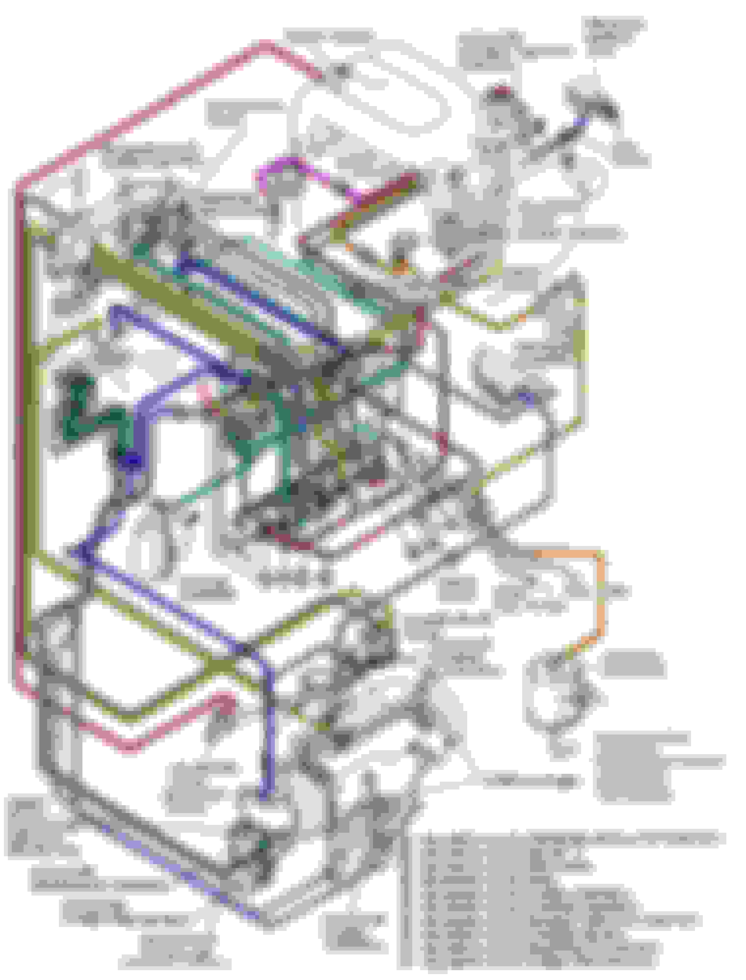
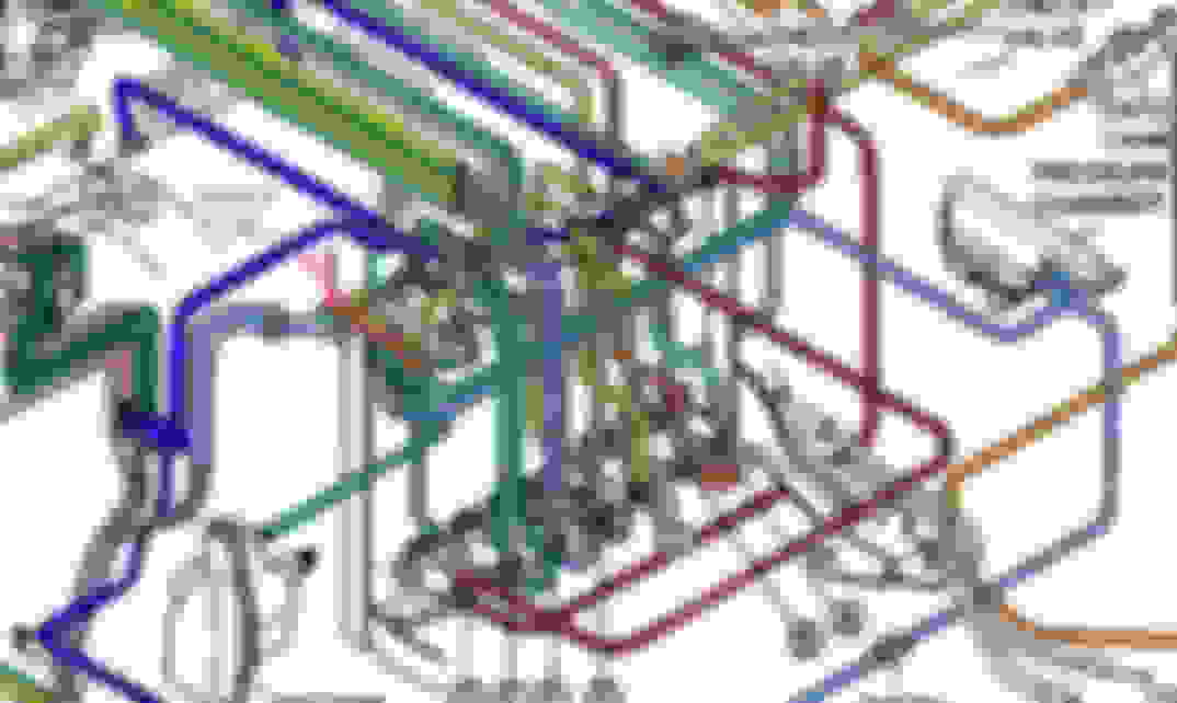
Below is the diagrams i have created along with the FSM ones please study these first and make sure you understand them, even if you dont you can follow the logic of the diagrams pipe for pipe to make sure they are connected to the correct pipes.
as you can see there not that clear so i have made improvements to help you ....
ok so ill start by explaining each control system and taking you throug it so you can follow the diagrams better.
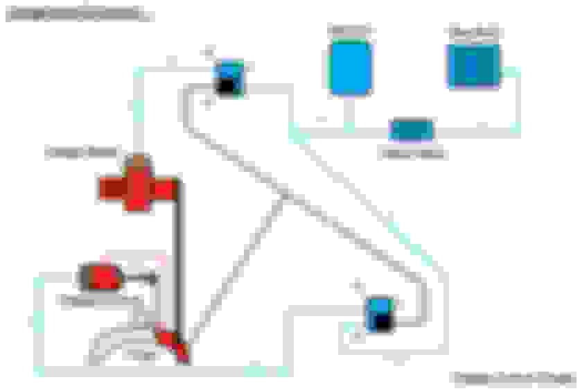
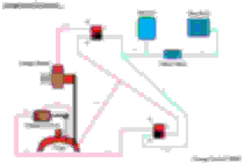
First we will start with the charge control and relief system.
i have already explained what these do but if you look at the diagram you will see the Y Pipe harvests both the charge relief and control actuators and these are controlled with 2 seperate solenoids connected to various places.
How it works...
The primary turbo is currently spooling from 1k RPM - 3k RPM at this point we do not want the second turbo to do anything so we need to deactivate it, here the charge control solenoid located bottom right of the diagram is set to the open position which means vacuum can pull the rod closed by appliying vacuum from port B on the solenoid from port A which is connected to the vacuum chamber and a check vavle which is connected to the intake manifold where the vacuum is made.
At the same time the charge relief solenoid is also open allowing vacuum to pull the plunger open in the same manor to allow any pressure produced from the second turbo to vent back in to the intake system or atmosphere depending on your setup.
When the second turbo is being spooled this system is still in the same state untill the second turbo has matched the primary at which point pressure from the Y Pipe line connected to the two solenoids equilises and pushes the two actuators closed, this is done when the ECU switches the solenoids and now we can see in the diagram below that vacuum is disconnected from these actuators and boost pressure is applied instead and that the charge control actuators valve has switched allowing flow from B to C and that the charge Relief solenoid has switched to B to A meaning the pressure from the Y Pipe is now in closed loop forcing the relief shut and the charge control open to allow the primary and secondary turbos to meet and produce boost. It is here you will notice a dip in pressure on the chage over and a rise as they both meet. This is becasue as the secondary turbo is engaged the pre control valve opens bleeding exxhaust gases to the second turbo to spool it up and thus a drop in pressure, as the turbos meet the same speed the pressure will rise, then when they are allowed to work together another dip in pressure will bee seen and should hold until red line.
Next up is the turbo pre-control
Here is the clever bit that mazda come up with to get the two turbos to work correctly. As you can see in the diagram the turbo pre-control actuator is connected on one side to the turbo outlet this is the primary turbos outlet and the other outlet connected to the solenoid. as the car is spooling up from 1 - 3k RPM the solenoid is open so the pressure from the turbos outlet is passed through the actuator to the solenoid from port A to B and back in to the turbos inlet pipe also known as the vacuum side, this keeps the flap closed and the second turbo shut off.
Last edited by Sheldrake godfrey; Apr 14, 2018 at 03:35 PM.
Reason: spanned in the comments instead of 3 different posts
In the next diagram you can see the opposite, as the car hits 3.5k RPM the second turbo is spooled up and this is achieved when the solenoid is closed causing the pressure from the primary turbo to bleed back to the actuator forcing the actuator open which will spool up the second turbo.
Turbo Control...
Now the second turbo has spooled to match the primary we need both turbos to be fully engaged to work together, this is achieved using the turbo control actuator and this uses two solenoids to do the job, one for vacuum and one for pressure. The pressure source is from a pipe that come from the Y PIPE and connects to the pressure chamber, the vacuum source is from the vacuum tank / manifold and when the turbo control isn't required the turbo control solenoid for vacuum is closed and the pressure solenoid is vented from B to C see below:
however when it is needed the pressure solenoid switches allowing pressure to flow from A to B which forces the piston to close and the vacuum solenoid open allowing vacuum from A to B fed from the vacuum tank and manifold to pull the piston opening the flap in the exhaust system.
The wastegate control is done in the same manor as the pre-control as you can see below:
now that we can see how the system works and what controlls it we need to be able to diagnose it.
To do this we need to check all the solenoids in the rack to see if they are working correctly.
As stated above they each have 3 ports or 2 ports, the 2 ports act as a switch allowing vacuum / pressure to flow through or not and the 3 ports have a bleed off port, this is so the actuators can reset or return to there previous state and this can only be done if the vacuum or pressure holding them closed / open is released.
So how to check the solenoids...
We need to warm an oven up to 120 degrees centigrade to simulate engine heat, believe me i did this on a cold test and they worked fine, i did the same test on a hot test and a few failed !!!.
First, the resistance test:
Use your multimeter and test the resistance across the terminals. It should be about 40ohms, or a little more if the solenoid is hot. If it shows a resistance above 60 or below 30ohms, junk it.
When the solenoid is powered off check that there is flow between C and B.
Then check with vacuum port A and check for leaks, there should be none, then apply 15PSI and check again for leaks...
Now energise the solenoid and check that C is closed and flow between A & B is true, then check if there is vacuum & pressure with no leaks on C.
Repeat the test after the actuator has been heated. if the actuator doesn't move bang it to free the plunger, however this means its damaged and failing under heat, if the solenoid fails any of these test bin it and replace !!!!, now its worth mentioning you can buy the original factory solenoids or buy a MAC 3 port one which will do exactly the same at a fraction of the price and last longer !!!!.
You don't need an expensive probe to actuate the solenoid just a 12v source from a battery !!!
Right providing the actuators are working well you need to check the vacuum lines to make sure they are connected to the correct ports to function correctly, they say a picture speaks a 1000 words well in this case it does unless you have the original FSM in which case it took me 3 weeks to fully decifer it and make a diagram that actually makes sense .
break down of the actuators :
Turbo Control – CLOSED then opened when needed
Wastegate & Pre-Control – Closed then opened when needed
Charge Relief – Open then closed when charge control is closed
Charge Control – Closed then open when needed
Double Throttle Control – Closed then opened when needed
You should be able to see that all solenoids are connected to actuators on port B and port A is the Vacuum or pressure source, and if it has it Port C is the dump source, follow the key here and you should be fine !!!
The key for the vacuum diagram is as follows:
A = Solenoid valve – Pressure Regulator Control (Fuel pressure)
B = Solenoid valve – Relief 1 (AWS System Secondary Air Control Pump)
C = Solenoid valve – Switching (AWS)
D = Solenoid valve – (EGR)
E = Solenoid valve – Turbo Control (2nd turbo actuator flap)
F = Solenoid valve – Charge Control (2nd turbo Y Pipe flap open / close)
G = Solenoid valve – Double Throttle Control
H = Solenoid valve – Charge Relief (BOV for second turbo)
I = Solenoid valve – Wastegate Control
J = Solenoid valve – Turbo Pre Control
Colours for the piping and connections:
A = Orange – Pressure Regulator Control
E = Blue – Turbo Control
F = Green – Charge Control
G = Red – Double Throttle Control
H = Yellow – Charge Relif
J = Pink –Turbo Pre Control
I = Green – Wastegate Control
Right now for my edited diagrams that should make more sense !!!
Trouble Shooting Actuators: (Attatch boost guage at numbered location)
First thing to check before anything is the solenoids for sticky plungers and leaking as above and to check the Actuators for leaks and smooth movements.
After this you need to check the vacuum and pressure tanks without these you will have boost problems.
Assuming you have no boost leasks and all your actuators are working correctly you need to check for broken or missing pipes in the rats nest. The diagram above is for a relocated rats nest and so diagnostics is easier to do as you can get to all the lines however you can T off the lines in various places without removing the manifold to test for issues.
How the turbo system should work..
Initially the primary turbo will be the only source of pressure and the manifold will be the only source of vacuum excluding the fact the presure and vacuum tanks which will hold the two forces needed. The primary turbo feeds the Pre-Control actuator and wastegates vacuum and pressure forces required to operate where as the charge relief and control actuators and solenoids use the manifold via the vacuum tank to obtain vacuum and the Y Pipe to feed the positive pressure required for both of these to work without the use of the Pressure tank. The Turbo control actuator is the only solenoid to use the pressure tank for operation.
So picture this, the car is accelerating from the stop possition, the wastegate, pre-control, charge relief and charge control are the areas to look at during the primary turbos boost condition. From stand still to 3k RPM the pre-control solenoid will be closed along with the wastegate providing overboost condition isnt true, the charge control flap will be closed and the charge relief will also be closed. When the car is transitioning to the second turbo around the 3-3.5k RPM the pre-control solenoid will start to open bleeding exhaust gases to the secondary turbo, whilst this turbo is spooling a slight pressure drop will occur on the primary turbo, the charge relief valve will also slightly open when the pressure on the second turbo spikes or spools too quickly as both turbos need to be running at the same speeds and pressure to prevent them fighting each other when they both suppliy boost, when pressure equilises the charge relief will start to close and the charge control will start to open allowing both turbos to meet and provide boost, at the same time the turbo control solenoid will also be opening and when both turbos match the turbo control flap will open fully and both turbos will function together.
If you find there is a problem here then find out where the problem occurs and check the following bearing in mind with out meeting the target boost of 10 psi on the primary turbo the second will not start to transition, like wise when the second turbo engages it will need to see 8 psi of pressure to match the now targeted pressure of 8 psi from the primary as the dip which is casued from suppliying the 2nd turbo has to be accounted for, once they meet they should rise together to meet 10 psi again and taper off to 8 psi up to redline.
Trouble shooting checklist, cross reference with the numbered grey circles on the diagram this is where you T the second boost guage to fault find.
1. Pressure chamber, the pressure chamber is used for the 2nd turbo control flap that engages the second turbo and isnt used for anything else, You should get boost pressure here and hold at the peak PSI of the cars capabilitys, minimum 10 PSI . once obtained it should never waver or leak down. If there is no pressure here or it doesnt match what the primary turbos boost levels reach something is wrong with the feed to the pressure tank which is fed off the y pipe, check for leaks!
2. Turbo Control Actuator for the 2nd turbo engagement, here you should see 0 PSI until the change over (3-4k RPM) when the second turbo is engaged, during pre spool you should see the pressure increase then hold. Once you throttle down and the RPMS drop below the pre controls parametres ( Under 3k RPM ) the boost guage will drop back to 0 PSI, if this does not happen check for leask from the actuator to the solenoid or for a sticky or non functioning solenoid
3. This is the cars main vacuum storage, like the pressure tank in number 2 you should see a negative vaccum number and this once obtained shouldnt waver or leak down. If you dont see this then check your check valves and lines between it and the manifold, also the other solenoids that share the vacuum line also need to be checked for leaks.
4. Charge Relief, here you should see no vacuum when the second turbo is disengaged, once the turbo is spooling a steady rise in negative vacuum should bee seen and the BOV will open, once spooled down the BOV will close again and 0 vaccum will be seen. So if you do not see this check to see if lines have come off or the solenoids are working correctly, also if the actuators are not working or stuck this will casue the system to fail.
5. Charge Control – here you should see vacuum when the second turbo isnt ready to engage and then positive boost when the flap is open and the second turbo is engaged, when the second turbo is disengaged the guage should show vacuum.
6. Double Throttle Control, here vacuum is applied during the warmup process, here you should see a minus vacuum number and once the car has warmed up slowly returning to 0 PSI as the vacuum has blead off and the extra throttle plenums will open. If there is a problem here check you lines and check control valve and actuators.
7. Charge Relief & Charge Control share a common pressure line to flip states, you should see this rise from 0 PSI to the cars maximum capabilities minimum of 10 PSI. This will occur when the second turbo is engaged and drop back to 0 once you throttle down.
8. Wastegate, here a negative vacuum number will be see until the wastegate is needed, then a positive pressure should be seen when activated.
9. Turbo Pre-Control, here a negative vacuum number will be see until the Turbo Pre-Control is needed, then a positive pressure should be seen when activated.
And here is the ECU pinout for the solenoids electrical signals :
Thats it i hope this has helped and if you are still stuck or need assistance please let me know and ill try my best but please i cannot stress enough, go over the diagrams and study them they will make sense eventually !!!.
and here is my finished nest and a few other pictures of pipes which may help you ....
I have a question.
Can the factory blow off valve and the re circulation valve (the identical looking valves on the Y pipe) be replaced by after market blow off valves (eg: HKS SSQV4 or Greddy) ?
yes you can , im using a forge recirculating valve in place of the original BOV and a forge piston dump valve to replace the factory one on the y pipe.