
N/a 20b hits record 475rwhp

N/a 20b hits record 475rwhp
Many of you already know the car, but here is a quick overview for those who don't.
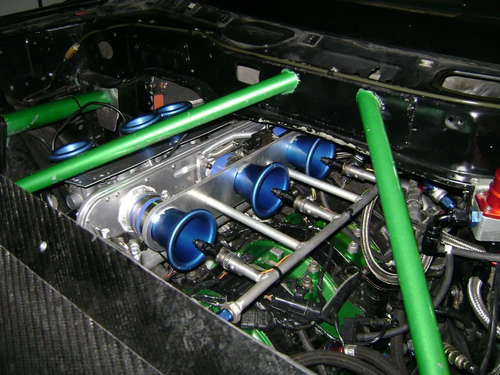
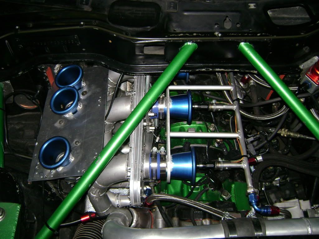
20b series C engine, 9.7:1 rotors balanced by CLR, Semi p-port, ceramic apex seals, mazdacomp drysump, Custom inconel header, custom slide throttle intake with mechanically staged peripherals. 3 x id 550cc 3 x id 1000cc 3 x 270cc injectors. Electromotive TEC3R ecu. 5.5 tilton triple disk clutch, taylor flywheel, T5 g-force dogox transmission.
Lots of work to get here, and shooting for more over winter! Thanks for everyone supporting us at Defined Autoworks! Check out www. definedautoworks.com for new updates and products.

Video
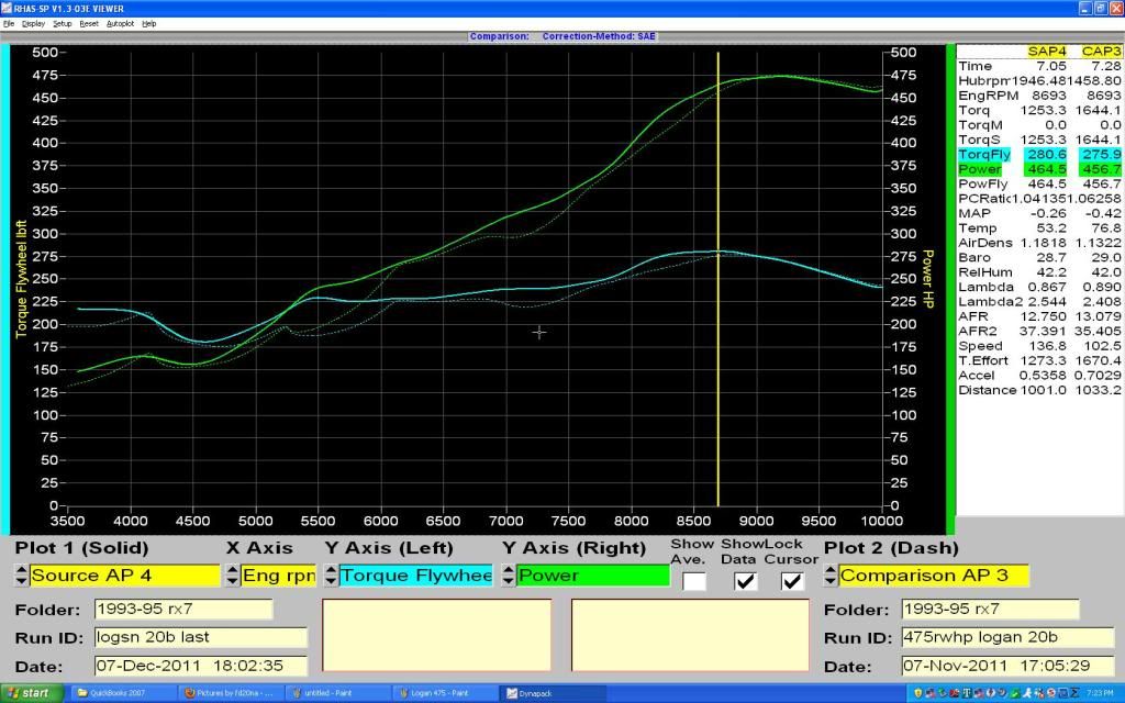
Dyno Chart
20b series C engine, 9.7:1 rotors balanced by CLR, Semi p-port, ceramic apex seals, mazdacomp drysump, Custom inconel header, custom slide throttle intake with mechanically staged peripherals. 3 x id 550cc 3 x id 1000cc 3 x 270cc injectors. Electromotive TEC3R ecu. 5.5 tilton triple disk clutch, taylor flywheel, T5 g-force dogox transmission.
Lots of work to get here, and shooting for more over winter! Thanks for everyone supporting us at Defined Autoworks! Check out www. definedautoworks.com for new updates and products.
Video
Dyno Chart
Last edited by GtoRx7.; Dec 8, 2011 at 07:17 PM.
And thanks!
Trending Topics
Old [Sch|F]ool


Joined: May 2001
Posts: 12,880
Likes: 577
From: Cleveland, Ohio, USA
I have a question regarding the fuel injector arrangement. How do you have the regulator set up, given that some of the injectors spray above the throttles and some below?
I'm contemplating a similar setup, primaries in the stock location, with the secondary injectors spraying into the throttle body, but figuring how to reconcile the regulator has me stumped. I guess I COULD just make sure to stage the injectors when manifold pressure is close to atmospheric, but somehow that still just seems improper.
I'm contemplating a similar setup, primaries in the stock location, with the secondary injectors spraying into the throttle body, but figuring how to reconcile the regulator has me stumped. I guess I COULD just make sure to stage the injectors when manifold pressure is close to atmospheric, but somehow that still just seems improper.
You have any more pics of your slide throttle bodies or info on them? That's if you would like to share it of course...
I built a pair myself while while in school for machining as a learning process. But I got stuck at the return spring and TPS set up. Any tips would be a big hep.
I built a pair myself while while in school for machining as a learning process. But I got stuck at the return spring and TPS set up. Any tips would be a big hep.
 Glad you have enjoyed the work. Means a lot to me!
I have a question regarding the fuel injector arrangement. How do you have the regulator set up, given that some of the injectors spray above the throttles and some below?
I'm contemplating a similar setup, primaries in the stock location, with the secondary injectors spraying into the throttle body, but figuring how to reconcile the regulator has me stumped. I guess I COULD just make sure to stage the injectors when manifold pressure is close to atmospheric, but somehow that still just seems improper.
I'm contemplating a similar setup, primaries in the stock location, with the secondary injectors spraying into the throttle body, but figuring how to reconcile the regulator has me stumped. I guess I COULD just make sure to stage the injectors when manifold pressure is close to atmospheric, but somehow that still just seems improper.
Glad you have enjoyed the work. Means a lot to me!I have a question regarding the fuel injector arrangement. How do you have the regulator set up, given that some of the injectors spray above the throttles and some below?
I'm contemplating a similar setup, primaries in the stock location, with the secondary injectors spraying into the throttle body, but figuring how to reconcile the regulator has me stumped. I guess I COULD just make sure to stage the injectors when manifold pressure is close to atmospheric, but somehow that still just seems improper.
I'm contemplating a similar setup, primaries in the stock location, with the secondary injectors spraying into the throttle body, but figuring how to reconcile the regulator has me stumped. I guess I COULD just make sure to stage the injectors when manifold pressure is close to atmospheric, but somehow that still just seems improper.
You have any more pics of your slide throttle bodies or info on them? That's if you would like to share it of course...
I built a pair myself while while in school for machining as a learning process. But I got stuck at the return spring and TPS set up. Any tips would be a big hep.
I built a pair myself while while in school for machining as a learning process. But I got stuck at the return spring and TPS set up. Any tips would be a big hep.
Thanks! It is on pump gas. Tried race gas and lost a bit of power. Torque is very high actually for the given displacement and rotary tax. A engine going to 10k is always going to have almost half the torque vs hp due to a function of math.
I never thought of using an fc tps. The tps use i was going to use cost over 200 dollars each. it was basically just a linear potentiometer similar to ones used on suspension adjustment setups. Ill check out the videos. Thanks.
Seriously complaining about the torque curve?  Haha. Usually being flat as a pancake all the way out would be incredible, but this is actually gaining torque the whole way up to nearly 9000RPM! Over 225ft/lbs (at the wheels) from pretty much the beginning of the graph. What other engines out there gain 50ft/lbs after 7500rpm. Check out this dyno graph for comparison.

This is from a car I used to own,a greddy turbo AP1 S2000. Torque is still slightly lower than this N/A 20B, but a very similar graph. You can see it still tapering off at close to 9000RPM though. These engines will never be torque monsters like high displacement V8s, but what it is making, and especially holding throughout the entire RPM range is very impressive.
Haha. Usually being flat as a pancake all the way out would be incredible, but this is actually gaining torque the whole way up to nearly 9000RPM! Over 225ft/lbs (at the wheels) from pretty much the beginning of the graph. What other engines out there gain 50ft/lbs after 7500rpm. Check out this dyno graph for comparison.This is from a car I used to own,a greddy turbo AP1 S2000. Torque is still slightly lower than this N/A 20B, but a very similar graph. You can see it still tapering off at close to 9000RPM though. These engines will never be torque monsters like high displacement V8s, but what it is making, and especially holding throughout the entire RPM range is very impressive.
Environmentally-Hostile
Joined: Sep 2005
Posts: 1,662
Likes: 3
From: Ennis/Arlington Texas
Just conjecture here, but what if you guys put some aluminum, higher compression rotors in that bad boy and spun it to 15,000rpm? Bet you would make over 600whp.
Either way, awesome, awesome work. You guys have my business when I'm ready for a 20b.
Either way, awesome, awesome work. You guys have my business when I'm ready for a 20b.
The dip has ben explained before. The dip is when we actuate the semi-p's with our foot on the gas. We are actuating the semi p-ports mechanically with the gas pedal at certain rpm's (delay in pushing full throttle). We are going to be actuating the semi-p's electronically when we have time to develop the system. We wanted to get all of the intake length testing, along with countless other things before we worried about small details.
Hope the explanation helps.
Hope the explanation helps.