
ITB's with stock ECU?

ITB's with stock ECU?
Im interested in building a setup focused around engine response and im tossing around the idea of building a streetport motor with an ITB setup. I dont want to ditch the stock ECU because its a streetcar and I have no interest in tuning and blowing up my engine.
Hypothetically one could create a custom intake box which housed the ITBs and connect it to the existing Air filter and AFM. Would using a stock ECU render the point of the modification useless? Im pretty sure the AE86 came stock with ITBs and used a similar AFM/MAF.
Let me know what you guys think
Hypothetically one could create a custom intake box which housed the ITBs and connect it to the existing Air filter and AFM. Would using a stock ECU render the point of the modification useless? Im pretty sure the AE86 came stock with ITBs and used a similar AFM/MAF.
Let me know what you guys think

alternatively, I recall a member on the forum by the name of kahren who made his one short intake which used the stock throttlebody without the plenum. He apparently made around 180 hp on stock ports with a tune. This would allow me to hook up the stock throttlebody to the rest of the intake but perhaps the gains in terms of response may not be so pronounced?
Joined: Mar 2001
Posts: 31,857
Likes: 3,243
From: https://www2.mazda.com/en/100th/
he was also using a Haltech.
his thinking on that was that the stock FC throttle body is 3x45mm throttle plates, which is bigger than say a 2x48mm IDA weber... so the stock throttle body was fine, its just the intake wasn't the right length, and too many bends, etc.
you see for yourself, straighten the intake out, and make it shorter and it shifts the power band higher in the Rpm range...

Junior Member
Joined: Oct 2013
Posts: 10
Likes: 0
From: richmond, va
The idea of building an airbox with the AFM feeding it and stock ecu will render terrible engine response as the readings from the afm will get to the computer before the air gets to your engine if that makes any sense. Its a bad idea. AFM's were not so good to begin with but in 1989 it was the best affordable EFI available. Now their is speed density tuning. Take advantage of the technological revolution and get a standalone, they are very powerful and well priced. If you are afraid of technology and by that I mean don't want to do all the wiring, then go with an IDA Carb and a distributor. for less than a grand you can be up and running although I find tuning Carbs harder than tuning EFI.
Old [Sch|F]ool


Joined: May 2001
Posts: 12,880
Likes: 577
From: Cleveland, Ohio, USA
The idea of building an airbox with the AFM feeding it and stock ecu will render terrible engine response as the readings from the afm will get to the computer before the air gets to your engine if that makes any sense. Its a bad idea. AFM's were not so good to begin with but in 1989 it was the best affordable EFI available. Now their is speed density tuning.
The airflow meter is already pretty far away from the engine, I don't see it as being a problem.
To add more "fuel" to the fire, people have converted 16v Volkwagens to independent throttles and kept the K-Jetronic (aka CIS) by doing exactly as has been described, running the throttle bodies to a plenum that pulls from the airflow flapper.
The main issue that I see with the Mazda system (it's just an implementation of L-Jetronic) is that Mazda also references manifold pressure, and the MAP sensor will give a different signal for independent throttles vs. a plenum. The possible saving grace here is that Mazda chose a really crappy spot for the MAP sensor feed, it comes right from one of the runners instead of the plenum. When i did my initial Megasquirt install, I chose the Mazda location and found the pressure pulses to make tuning difficult, so i moved it to the plenum and all was well.
The POINT of that is, Mazda already engineered their ECU to work with a pulsey, ITB-like vacuum signal. So you may be good to go as-is.
Trending Topics
This would be really easy to implement.
Use Holley style 5150 shorty intake manifold, 5150 throttle body, boost hat and plumb your 2ndary injectors into the 2ndary runners, IAT into boost hat, etc.
Run a tube from your boost hat to AFM/filter.
No need to put a lot of work into fabricating an intake/plenum, etc just to get your ITBs 4 in one row instead of 4 in a circle.
Joined: Mar 2001
Posts: 31,857
Likes: 3,243
From: https://www2.mazda.com/en/100th/
the BMW M3's and M5 are like this, and they seem to do ok, dare i say they are the ultimate driving machine (, but god help you when it breaks)

Senior Member
Joined: Jun 2012
Posts: 462
Likes: 0
From: Michigan
Speed density was the original automotive EFI as used by Chrysler in 1958 and later Bosch D-Jetronic in the very late 60s up through the 70s (which just looks like they bought the Chrysler setup and modernized it). Measuring airflow directly was a major step forward. Mass airflow systems ARE the best way to run an engine, period, but they are finicky to set up for one-off installations (something as simple as rotating the sensor 30 degrees can have a deamatic effect on airflow measurement) so it only makes sense to run standalones off of speed-density because you don't have to hand-tweak a MAP sensor calibration for every application. I've seen MAF skew as high as 30% just from a cold air intake installation! Fortunately airflow meter systems are much more tolerant than MAF as far as skew is concerned.
The airflow meter is already pretty far away from the engine, I don't see it as being a problem.
To add more "fuel" to the fire, people have converted 16v Volkwagens to independent throttles and kept the K-Jetronic (aka CIS) by doing exactly as has been described, running the throttle bodies to a plenum that pulls from the airflow flapper.
The main issue that I see with the Mazda system (it's just an implementation of L-Jetronic) is that Mazda also references manifold pressure, and the MAP sensor will give a different signal for independent throttles vs. a plenum. The possible saving grace here is that Mazda chose a really crappy spot for the MAP sensor feed, it comes right from one of the runners instead of the plenum. When i did my initial Megasquirt install, I chose the Mazda location and found the pressure pulses to make tuning difficult, so i moved it to the plenum and all was well.
The POINT of that is, Mazda already engineered their ECU to work with a pulsey, ITB-like vacuum signal. So you may be good to go as-is.
all 2nd gens also ran MAP's (boost sensors),and the NA's only used it to lightly vary the RPM when the secondaries come online. With my ported S4 6 port, I found that the engagement of the secondaries was too random, so i left the boost sensor plugged in, and just removed the vac source. This made the engagement of the secondaries consistent and predictable.
a little bit of a thread necro, but I have some ideas how to execute this.
For starters my car is an S5 and needs to pass smog where i live, it would be ideal if i could keep the LIM and airpump to pass smog when i need too. Really then what i would be building is a straight section of intake which links up the throttle body with the LIM in a "near" vertical manner. By removing the UIM and plenum, im going to need to loose the BAC and figure out some way to keep the ecu happy while simplifying the vacume hoses. if i keep the LIM it would be nice if i can keep the 6port system working but i need to read up on the solenoid rack and what systems are important.
What the ECU needs to run the engine at WOT and what it does to keep it idling nicely are two different things from what i understand. Some people can run their cars without a BAC and some have trouble so how well thats going to go over with the stock ECU i really dont know.
Also about the intake, AFM and throttle body, I was thinking of just rotating the existing throttlebody and use the plastic elbow to link it up to the AFM. I will probably replace the stock plastic pipe with a less restrictive aluminum one which i could possible shape to ensure everything lines up.
All of this is theoretical and im sure there is something im missing from the equation. Like figuring out the throttle cable or exactly how im going to mount injectors ect.
Heres kinda what I had in mind. Essentially I would be adapting the throttlebody into the LIM instead of the block itself. I would have to mount it at a slight angle to help clear the hood and to ensure proper throttle cable function. This is probably a stupid question, but is there any reason I shouldnt mount the injectors and secondary fuel rail horizontally as opposed to vertically?
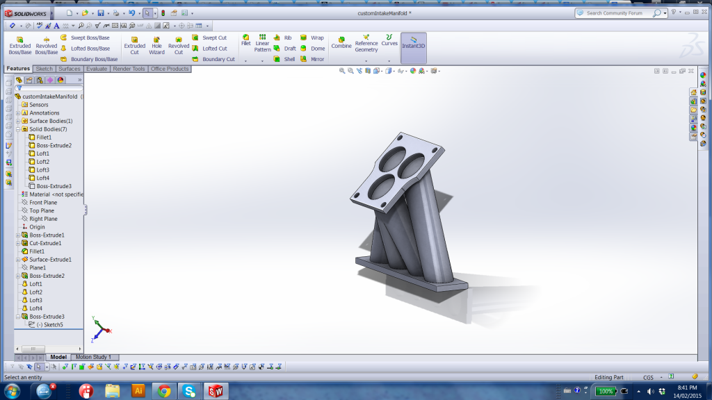
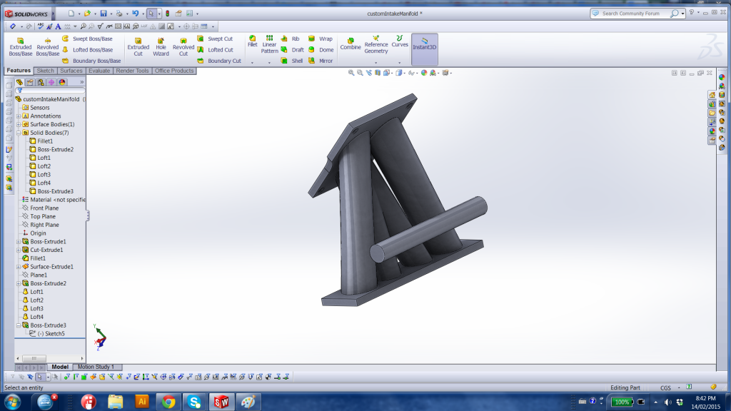
This is really quick and dirty CAD but it will suffice for the time being


This is really quick and dirty CAD but it will suffice for the time being
+ i would add a heatshield to the design, not just to help minimize heat soak, but to help protect wires and electrical components from the heat. From what i can understand the stock intake is less exposed to heat radiation than what your design has, and it has water channels to keep heat down.
Either just run a simple single sheet of steel, or a double plate with air in between, and maby try to feed air from the front bumper to it, and measure temp difference, to see if it would help any.
Here is a link to an accurate drawing of the ports on a 6 port 13B engine, Merged the sec and 5/6 ports, since i'm using just one runner for them in my design. It is drawn up in Inventor 2014, so not shure if you can use it. Printed it and it matches up against a 6 port gasket.
https://www.dropbox.com/s/vrm4wo2bvl...flens.ipt?dl=0
nonetheless, heat shielding is a good idea
hmm, why not mount it to the block? It has been done with a similar manifold before, and with great results.
Seems to me like it if you would gain any power, it would not be very much, since the lim still is a restriction at higher rpm. your design is just a slight modification of the uim, not shure it is worth the effort.
But i could be wrong, so if you are going to try it then it would be cool if you could dyno test before and after, to see what gains you get.
the reason i wanted to keep the LIM is because i still need to pass emissions testing in my area, and I want to keep the car fairly "stock ish". When i drove the car with the aux ports wired open I felt a significant drop in low end power and I didn't like it very much.
its a gamble but i want to see if there are any gains to be had with shortening and straightening the upper section of the intake. We'll see if i get around to building a prototype and testing it on the road
its a gamble but i want to see if there are any gains to be had with shortening and straightening the upper section of the intake. We'll see if i get around to building a prototype and testing it on the road

IMO, use curved tubes to get the TB horizontal. I have thought about this also but I want th 5/6 ports working. I believe it still shortens the intake considerably. I just don't like the single primary throttle and the merging of the two primary ports.
What would be really cool would be motorcycle ITB's addapted to the 6-port lower manifold. Even better if one could figure out how to stage the throttles, you know, not having the secondaries open until the primaries open so far. I wonder if an airbox over this set-up would work with the stock ECU as discussed above
What would be really cool would be motorcycle ITB's addapted to the 6-port lower manifold. Even better if one could figure out how to stage the throttles, you know, not having the secondaries open until the primaries open so far. I wonder if an airbox over this set-up would work with the stock ECU as discussed above

One needs a TPS with a hole through it. It's the only way to separate the primaries and secondaries using four TB's. I'm thinking of getting another one like the one on my motorcycle TB's I intend to use to see if it can taken apart and altered. It appears it can be disassembled, at least to a certain extent.

Full Member
Joined: Nov 2011
Posts: 105
Likes: 0
From: orange, ca
I was thinking in a similar fashion, using either two VW throttle bodies, or four individual TB's with a progressive linkage: that way I can even keep the primary/secondary throttle split. It would require modding the linkage to use the factory tps, but it's doable.
With the natural design of the S5 NA LM the TPS needs to be on one of the two inner TB's and then you have to have linkage that runs the outside two. I would like to stay within the boundaries of the original design. The TB's are actually truely individual and are bolted to a rail. The way they connect together is interesting. To start swapping them around requires some thought. I would be willing to make custom rails (simpler than you might think and then a new fuel rail to accommodate new, custom spacing.
To activate the outer two TB's, copy a mechanical secondary four barrel linkage design.
The motorcycle TB's are kinda sweet. They come with a TPS, fuel rail, pulsation dampener, vaccuum collector with check valve, what I think is plumbing for some sort of IAC, and have/take EV14 fuel injectors. The cheapest way out is to use as is.