Megasquirt MSnS_Extra Daughter Board Available Soon - Aimed for Rotary Application Users
 09-14-05, 03:57 PM
#26
MegaSquirt Mod
no, it doesn't have a built in wideband controller. You buy something like a techedge controller or an Innovate LC-1, and run the 0-5v analog output from the controller into the megasquirt. This was supported with the 2.2 board as well.
 09-14-05, 05:35 PM
#27
Navy MarCom
iTrader: (3)
Join Date: Jul 2004
Location: On a Boat!
Posts: 812
Likes: 0
Received 0 Likes
on
0 Posts
ok cool I thought I say a daughterboard layout that has coloured areas for different add on devices like solenoind controllers and such.. ?? don't know what I was looking at then . well cool I guess I'll be contacting glens garage for the works.. thanks guys..
09-14-05, 11:45 PM
#28
no clever remarks...
Join Date: Dec 2004
Location: WA State
Posts: 778
Likes: 0
Received 0 Likes
on
0 Posts
This may be a dumb question, but here goes... Do daughterboards just directly plug into the megasquirt main board or is there soldering involved (no prpb if there is I can solder very well)? SO basically then if I got the daughterboard and wasn't using the relay board I could run the MSnS code and run stock leading and trailing without building the extra circuit in the proto area? Thanks.
09-15-05, 07:32 AM
#29
MegaSquirt Mod
the daughterboard requires soldering. You have to solder all the parts onto the daughterboard, then solder wires between the daughterboard and the megasquirt.
you could run stock leading and trailing without the extra circuit in the proto area in many ways. You could certainly use the daughterboard, but you could also get away with just cutting 2 teeth out of your CAS, and just using the v3 board's built-in vr sensor conditioner.
pmrobert used the "cut 2 teeth out of the CAS" method.
Ken
09-16-05, 08:53 PM
#31
no clever remarks...
Join Date: Dec 2004
Location: WA State
Posts: 778
Likes: 0
Received 0 Likes
on
0 Posts
Thanks, seeing as I will be keeping the car around for a while after making the conversion I do not see cutting teeth as being a big deal in the long run... especially since pmrobert has had no issues and he has been running it that way for several thousand miles. HE is also using primary only as far as I know, but maybe he has since switched to the new code. Chime in pmrobert and let us 12a guys know how it is going.
09-16-05, 09:35 PM
#32
MegaSquirt Mod
I don't think he's been using the stock CAS for thousands of miles. He used the HEI with a CAS that has 4 teeth and leading only for a while.
I think he just recently switched to the CAS with the teeth cut out... I also think he's directly driving a leading wasted spark coil with a vb921, and using a stock fc trailing ignitor with coils for trailing. The info is in one of the other threads if it's not in this one.
I think he just recently switched to the CAS with the teeth cut out... I also think he's directly driving a leading wasted spark coil with a vb921, and using a stock fc trailing ignitor with coils for trailing. The info is in one of the other threads if it's not in this one.
10-21-05, 11:45 PM
#34
Senior Member

Join Date: Oct 2005
Location: High Point North carolina
Posts: 417
Likes: 0
Received 0 Likes
on
0 Posts
error,First thanks for giving us all a nice board to solve many issues. I got mine today in the mail from glens garage. Assembly was very straight forward but have just 1 question please. The transistors Q1,Q2 etc etc etc dont have a flat spot printed on the board like a MS does. Does polarity not matter on this circuit? I've looked at the schematic but just want to be certain on this one. Thanks in advance,custom13B
10-22-05, 12:41 PM
#37
MegaSquirt Mod
haha, yeah, most of the people who have built v2.2 megasquirts would've already known that. I forgot that the v3 board has the new silk screen with the flat spot instead of the tab thing.
10-22-05, 07:05 PM
#38
Senior Member
Join Date: Oct 2005
Location: High Point North carolina
Posts: 417
Likes: 0
Received 0 Likes
on
0 Posts
well stoopid me...feel stupid anyways. Anyways thanks again for the tip. Do you happen to know if you buy the pre made engine cable for the MS if it comes labeled ex injector,at sensor etc etc? Or is it like everything else with MS where you have to search for hours to find info? I spent a solid hour searching the MS site...gotta say its the most confusing site Ive ever seen. I did learn a lot but of course raised even more questions. Thanks again,custom13B
10-22-05, 08:36 PM
#39
MegaSquirt Mod
depends on who you get it from... the one from rs-autosport has lables on the wires all the way up and down the wire...
However, none of the pre-made harnesses take into account things like ignition, so none of the wires to the ignitors would be labled....
Also, you'll need to find some shielded 4-conductor cable for your CAS, otherwise you risk a noisy signal from the CAS, which can cause ignition misses and such.
However, none of the pre-made harnesses take into account things like ignition, so none of the wires to the ignitors would be labled....
Also, you'll need to find some shielded 4-conductor cable for your CAS, otherwise you risk a noisy signal from the CAS, which can cause ignition misses and such.
10-22-05, 11:28 PM
#40
Senior Member
Join Date: Oct 2005
Location: High Point North carolina
Posts: 417
Likes: 0
Received 0 Likes
on
0 Posts
Ever get the feelin Rx-7 are like high maintence women?? Sure they look nice and are fun ...but damn they require a lot of special things. Took gf to dinner=45.00.....filled RX-7 with premium 45.00. Hmmmmm ,,,I have the sheilded cable already. Thanks again,custom13B
10-22-05, 11:36 PM
#41
MegaSquirt Mod
I understand what you're saying, but the shielded wire is needed for any car with VR sensors... the sensors themselves and the wires they connect to are like antennae for noise.
10-23-05, 01:08 AM
#42
Senior Member
Join Date: Oct 2005
Location: High Point North carolina
Posts: 417
Likes: 0
Received 0 Likes
on
0 Posts
I understand and thanks for the explanation. I've been searching the MS site lately and its difficult to find the needed info there. Could you possibly show how error's daughtercard is wired to both the MS and ignition? I am using the v3 board and only 1 VR circuit on the daughter board per your previous posts. I'm using the v1 chip and HC908 processor. I found error's post and it helped some but your explanations are always so much easier to understand. And from there I will eventually need a wiring diagram from the db37 to the engine. Hope Im not getting too far off topic. And thanks again for the input.
10-25-05, 11:52 PM
#43
Full Member
Thread Starter

Join Date: Mar 2002
Location: Calgary, Alberta, Canada
Posts: 117
Likes: 0
Received 0 Likes
on
0 Posts
Revised Wiring Instructions
Here it Is!
Connections and Wiring
----------------------
+5V Power and GND
+5V - +5 Volt from MS (Powers: Seq. Shift Lights, Nitrous Control, Launch Control, Dual VR
Conditioning, and BOTH Table Switching)
GND - Ground for whole board
Dual VR Conditioning Circuit
T1 - VR Sensor #1 Input (To Base wheel - i.e. 2pin Wheel in rotary)
T5 - VR Sensor #1 GND /w Load Resistor
T3 - Conditioned Output for VR Sensor #1 [Pin 11 on U1 on MS Board]
T2 - VR Sensor #2 Input (To Reset wheel - i.e 24pin wheel in rotary)
T6 - VR Sensor #2 GND /w Load Resistor
T4 - Conditioned Output for VR Sensor #2 [Pin 6 on U4 on MS Board]
T1 and T5 should be for the 2 pin wheel
T2 and T6 should be for the 24 pin wheel
Sequential Shift Lights
T7 - Input #1 [Pin 11 of U1 on MS Board]
T8 - Input #2 [Pin 10 of U1 on MS Board]
T9 - Upper Limit LEDs
T10 - Med Limit LEDs
T11 - Lower Limit LEDs
Outputs 1 to 4
T12 - Output 1 [X4 Jumper on MS Board]
T13 - Output 2 [X5 Jumper on MS Board]
T14 - Output 3 [Top Leg of R14 on MS Board]
T15 - Output 4 [Right Leg of R26 on MS Board]
T16 - Output 1 Relay
T17 - Output 2 Relay
T18 - Output 3 Relay
T19 - Output 4 Relay
T20 - +12V Power for Relays [To Battery]
Table Switching (Active High Input)
T21 - 12V Switched from Clutch Switch or Knock Circuit
T22 - Output [JP1 pin 6 on MS Board]
Table Switching (Active Low Input)
S1 - Active Low Switch Input [Toggle Switch to GND]
T38 - Output [JP1 pin 6 on MS Board]
Boost Control
T23 - Output [X4 Jumper on MS Board]
T24 - To Fast Acting Solonoid Valve
Water Injection Control
T25 - Output [X3 Jumper on MS Board]
T26 - To Fast Acting Solonoid Valve
*You must use one of the outputs in the Output circuits to X2 Jumper on the MS Board
Nitrous Control
T27 - Output [Pin 6 of JP1 on MS Board]
T28 - Anti-Lag Switch
T29 - Relay 1 Contact
T30 - Nitrous/Fuel Solenoids
*You must use one of the outputs in the Output circuits to X3 Jumper on the MS Board
EGT Logging
T31 - To K Type Sensor (Alumel [Red]) + ***Splice into a Ground from the Daughter Board
T32 - Cromel (Yellow)
T33 - Output [To X6 Jumper on MS Board]
2nd O2 Sensor Input
T34 - Output [Jumper X6 or X7 on MS Board]
T35 - Input from 2nd O2 Sensor
Launch Control
T36 - Output [Pin 4 of JP1 on MS Board]
T37 - Clutch Switch (+12V Switch)
Last edited by muythaibxr; 10-29-05 at 04:27 PM.
10-26-05, 06:45 AM
#44
MegaSquirt Mod
NOTE: the shift light feature doesn't work if you're using the stock CAS... You can only use one or the other.
Otherwise thanks for posting that error*! That'll most likely go in the FAQ thread.
Otherwise thanks for posting that error*! That'll most likely go in the FAQ thread.
Last edited by muythaibxr; 10-26-05 at 06:48 AM.
10-27-05, 05:47 PM
#45
Senior Member
Join Date: Oct 2005
Location: High Point North carolina
Posts: 417
Likes: 0
Received 0 Likes
on
0 Posts
First thanks to both error and muythaibxr for all your help so far. I understand that diagram but still have a question. I do not understand where your getting the G+ G- Ne+ Ne- from. I have the CAS and both coil packs removed and right in front of me. The CAS has 4 wires coming out with no lettering or labels inside it. Those wires are red and a white for the 24 tooth wheel and green and a white/black tracer for the 2 tooth wheel. The leading coil pack ignitor has 2 wires coming out 1 red and 1 tan the red goes to GT on ignitor and the tan goes to B for battery power. The trailing pack has 4 wires besides the power wires. Those are yellow grey white and red. yellow goes to Tach on the ignitor grey goes to CPU1 white goes to C1 and red goes to ST. I also looked at the factory schematic and nothing is labeled Ne= Ne- G- G+. Am I missing something obvious here? Really frustrated and everythings built and ready to be installed. Would greatly appreciate some feedback on this,Thanks in advance.
10-27-05, 06:26 PM
#46
RX-7 Alumni
For Discussion
Here's a draft drawing I've had in work for a while. Note the connections are not specifically for the Error* board, but should still help you.
Three things to note:
1) The connections have not been verified by anyone yet--so use at your own risk.
2) The ??? connection on the MS boards are any of the MS ground connections on the DB-37, and the DB-27 should read DB-37.
3) The S5 only jumper is actually on the other side of the ECU plug (same difference).
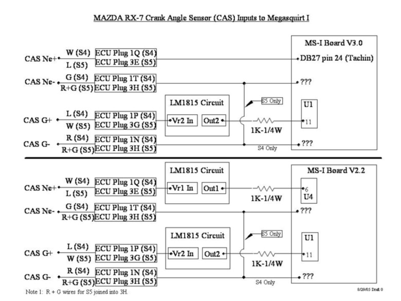
I'm hoping by posting this drawing we can work out any bugs and then I can finalize the drawing for ALL to use. The reason it is blurry is cause the forum only allows up to 100k file size. Perhaps in the future I can find a better format that will allow better resolution.
Scott
p.s. I also have one done for the coil connections.
Three things to note:
1) The connections have not been verified by anyone yet--so use at your own risk.
2) The ??? connection on the MS boards are any of the MS ground connections on the DB-37, and the DB-27 should read DB-37.
3) The S5 only jumper is actually on the other side of the ECU plug (same difference).
I'm hoping by posting this drawing we can work out any bugs and then I can finalize the drawing for ALL to use. The reason it is blurry is cause the forum only allows up to 100k file size. Perhaps in the future I can find a better format that will allow better resolution.
Scott
p.s. I also have one done for the coil connections.
Last edited by Rex4Life; 10-27-05 at 06:29 PM.
10-27-05, 08:12 PM
#47
Senior Member
Join Date: Oct 2005
Location: High Point North carolina
Posts: 417
Likes: 0
Received 0 Likes
on
0 Posts
Rex4life....Thank you thats very easy to understand! Truly appreciated. That coil diagram would be great if you dont mind posting it. Still wonder where the labels Ne and G came from but it dosnt matter at this point. I am just so happy to finally move forward with the wiring. Only thing left is the colis now. Thanks once again.
10-27-05, 09:27 PM
#48
RX-7 Alumni
Originally Posted by custom13B
Rex4life....Thank you thats very easy to understand! Truly appreciated. That coil diagram would be great if you dont mind posting it. Still wonder where the labels Ne and G came from but it dosnt matter at this point. I am just so happy to finally move forward with the wiring. Only thing left is the colis now. Thanks once again.
On this one I only did it for the v3.0 board--v2.2 is basically the same except the component IDs are different.

HTH,
Scott
p.s. I have no idea how to configure the software to make this all work. I'm hoping Ken could start a "software" faq to help us all share info about configuring Megasquirt to work for a rotary setup.
Last edited by Rex4Life; 10-27-05 at 09:29 PM.
10-27-05, 09:31 PM
#49
Senior Member
Join Date: Oct 2005
Location: High Point North carolina
Posts: 417
Likes: 0
Received 0 Likes
on
0 Posts
Rex you made my day! Been thinkin about this constantly. I actually woke up in the middle of the night last night dreamin about wiring this,,,yea I have issues. Anyways thank you very much!
10-27-05, 09:38 PM
#50
RX-7 Alumni
Oh yea, If you guys find ANYTHING that needs to change on those drawings--PLEASE let me know ASAP. I'll get it fixed and posted in no time.
I did these drawings based on everything I could find from Ken and Roger (including a few PMs). They've been doing the hard work so I thought I could help out with documentation.
Scott
I did these drawings based on everything I could find from Ken and Roger (including a few PMs). They've been doing the hard work so I thought I could help out with documentation.
Scott
Last edited by Rex4Life; 10-27-05 at 09:43 PM.