
Megasquirt I can see the light!!... but need a little help.


Thread Starter
Joined: Jul 2006
Posts: 849
Likes: 2
From: Orlando/Winter Park
I can see the light!!... but need a little help.
Well... I've got everything pretty much everything working now with the MS.. getting good readings on all sensors, spark to leading plugs on cranking.. but can't get it to start. I think I've already figured out the problem but I just want to be clarify a couple things. I was using the 11,1,5,7 settings but had stabbed the CAS for 1,3,7,9... thus explaining the no starting. So, I'm going to check that in a bit and see if it helps.
But for clarification can someone tell me which colors are what regarding the CAS. I want to make sure I've got the right wires going to the right places.
Additionally these are the settings I'm using for spark:
trigger angle:60
cranking advane:0
trim angle:0
thanks guys....
I'm getting close!!!!
But for clarification can someone tell me which colors are what regarding the CAS. I want to make sure I've got the right wires going to the right places.
Additionally these are the settings I'm using for spark:
trigger angle:60
cranking advane:0
trim angle:0
thanks guys....
I'm getting close!!!!
MegaSquirt Mod
Joined: Sep 2004
Posts: 4,721
Likes: 1
From: Maryland
Make sure you deflood the engine after cranking without starting.
If I remember correctly, green is G+, red is Ne+, white with a black stripe is G-, and white is Ne-...
I might be wrong though, it's been a while since I've had to mess with it.
Ken
If I remember correctly, green is G+, red is Ne+, white with a black stripe is G-, and white is Ne-...
I might be wrong though, it's been a while since I've had to mess with it.
Ken
Thread Starter
Joined: Jul 2006
Posts: 849
Likes: 2
From: Orlando/Winter Park
thanks Ken... I posted another thread I could use your help with. Also, is it ok that i tied both of the CAS grounds to pin 7 in the MS, or do they need to be grounded individually??
Thread Starter
Joined: Jul 2006
Posts: 849
Likes: 2
From: Orlando/Winter Park
i hate to be talking to you in 2 diferent threads Ken, so if you just want to stay in one it's ok by me. As for the grounding near the lm1815, if I soldered a wire to Pin 2 on the LM1815 and ran it out of th MS case and tied it to the G ground would that help? I've got a whole crap load of tach noise/ etc.
MegaSquirt Mod
Joined: Sep 2004
Posts: 4,721
Likes: 1
From: Maryland
As I said in the other thread, tach noise is usually due to poor/dirty grounds. Where did you ground the MS?
Also, If pin 2 was grounded on the lm1815 (sorry I don't have the pinout memorized) then that should help. If it didn't, you can also put a .01 uF capacitor across the G+ and G- pins going into the MS... I've had to do that on a couple of cars to clean up a messy tach signal. You might want to start with a .001 uF cap, and move to a .01 uF cap if the .001 doesn't work.
Ken
Thread Starter
Joined: Jul 2006
Posts: 849
Likes: 2
From: Orlando/Winter Park
i grounded th MS through the factory harness... when i bought the MS.. all of the individual grounds where spliced together into one single thick ground with a ringlet attatched as if to bolt it to a chassis ground... the previous owner was using this unit for fuel only. I cut most of the grounds free and wired them to individual grounds in the existing factory harness, using a pin read out I had found here on the forum. How would i go about adding the capacitor to the pins as described above, please forgive me I'm a bit of an electronics newb but very technically adept in mechanics, so I'm doing my best with this side of the project. I appreciate your guys help it's just that sometimes your guys' help goes over my head. I'm sure it's a little hard for you to try to think in basic mode, having so much experience with this, but It would make it a little easier for me. thanks
Trending Topics
MegaSquirt Mod
Joined: Sep 2004
Posts: 4,721
Likes: 1
From: Maryland
Well, by "clean up the grounds" I mean go under the hood, and anywhere there's a ground coming out of the stock harness, clean up the ring terminal and the place it bolts to so there's no scale or corrosion on it. 90% of the time, this is enough to get rid of noise on crank.
For the capacitor, you would just put it across the G+ and G- wires where the solder to your daughter card that has the lm1815 on it.
Start with a .001 uF capacitor, and if that doesn't work, switch to a .01 uF capacitor.
Ken
For the capacitor, you would just put it across the G+ and G- wires where the solder to your daughter card that has the lm1815 on it.
Start with a .001 uF capacitor, and if that doesn't work, switch to a .01 uF capacitor.
Ken
Thread Starter
Joined: Jul 2006
Posts: 849
Likes: 2
From: Orlando/Winter Park
I cleaned the grounds when installing the new engine, so I'm confident those are good... but I'll double check. also I'm not using the daughter card, i actually built the 2nd VR circuit in the proto area of the v3 board. I'm going to try grounding the G- to the ground of that circuit and see if it helps. Currently I have both the Ne- and G- grounded to the same MS ground, I'm thinking that could be the problem.
are you using the 2nd gen wiring harness? I know that it has all 4 wires from the CAS in a shielded sheath to help prevent noise. If you run them all seperately, you will get a lot of noise.
Thread Starter
Joined: Jul 2006
Posts: 849
Likes: 2
From: Orlando/Winter Park
i'm using the S4 harness... so, yes, my CAS wires are shielded. I did have both of the CAS neg wires grounded to pin 7 of the MS connector I' m in the process of adding a pin to the DB37 and wiring a ground from my LM1815 circuit to the pin, I'll then hook G- (blue wire in my S4 harness) to this pin/ground and see if that helps the noise.
Thread Starter
Joined: Jul 2006
Posts: 849
Likes: 2
From: Orlando/Winter Park
Thread Starter
Joined: Jul 2006
Posts: 849
Likes: 2
From: Orlando/Winter Park
Ok... well, I'm about ready to pour a bunch of gasoline on this MS and drop a match. I'm seriously at my witts end with this thing...6 days straight and I can't even get the damn thing to start. 6 days ago it would start with no problem, and now I can't even get a burp from it. I rewired the G- to it's own seperate pin (3) going directly to the ground of the LM1815 circuit, that did seems to help with the tach spikes a bit, BUT they're still there, AND the car stil won't sart. I stabbed the CAS for the 3rd tooth from the 2 tooth wheel and using 1,3,7,9 settings. Trigger angle is 60, Cranking advance is 0, trim angle is 0. I put fixed angle to -5 and put the timing light on it while cranking and lined up the CAS with the yellow leading mark. I then set fixed angle back to -10. I put in new plugs, made sure the engine was not flooded, and still... NOTHING!!! I can't understand how this ECU can't be working. I have spark, albeit a little intermitent due to the tach spikes, fuel (I can smell it, and the PW gauge is reading on Megatune) and my compression is GREAT. I'm sure I must be missing something... but I don't know what. I'd be happy with anything right now, I don't even get a miss... nothing... just steady cranking with the RPM's bouncing between 200-400 and an ocassional spike, usually on the initial crank, and as soon as the key is let off. I'm so lost!!!!!!!! I do have the MS-Extra daughtercard and all the components, if anyone thinks it'd be a better idea to build the second circuit on the daughtercard and connect it to the V3 board I'm up for that, I just don't quite understand how I should hook it up to the V3 board.....??????
Please guys, save my sanity, and this Megasquirt.
Please guys, save my sanity, and this Megasquirt.
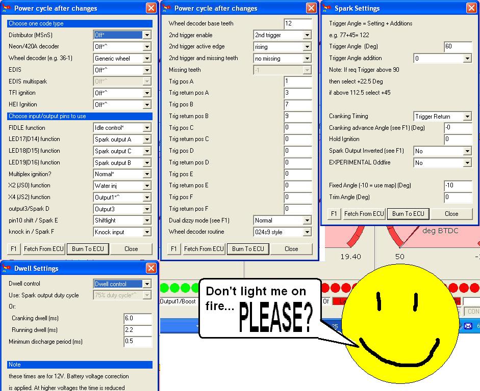
Ok, I just found the pin-outs and some info that I wrote down when doing mine with the CAS. The wires in the engine harness for the CAS correspond to the signals in the following way:
Vr2 In --------- Crank Angle Sensor (+G) ----1N ---- green
Vr2 Ground -- Crank Angle Sensor (-G) -----1P ---- blue
Pin 7 ---------- Crank Angle Sensor(-Ne) ----1Q --- white
Pin 24 --------- Crank Angle Sensor(+Ne) ---1T ---- red
Make sure that you have them going to the right place, and if you do, make sure that you are triggering off of the rising edge. also, use 024s9 style. Have you actually pulled the plugs and checked that they're sparking? If so, what color is the spark? It should be a nice strong bluish-white, if its yellowish-white, then either the plugs are done, the plug wires are worn out, or the coils are pretty weak.
Here are my settings so far (sorry for the big picture):
Also, for the hell of it, the whole list of harness connections I used when wiring up the DB37 connector (note, i didnt make an intermediate harness, i just hacked the emissions harness straight to the DB37, and then used part of the original ECU connector to go from the emissions harness to the front harness). Note that your connections at the DB37 connector may be different, especially for pins 2-6, 25,27,29 and 31. The shift indicator light also doesnt work properly, but im not too concerned about it, thats what the buzzer is for.
1
2-----G- CAS blue --------------------------------------1P
3-----G+ CAS green -------------------------------------1N
4-----IGT-L, Leading Timing, neg. LED 14----------------1V
5-----IGS-T, Trailing Select,neg. LED 15----------------1U
6-----IGT-T, Trailing Timing,neg. LED 16----------------1X
7----Ne- CAS white--------------------------------------1Q
8----Ground-------------------------------------connect to below
9----Ground-------------------------------------2R (which is ground per FSM)
10---Ground------------------------------------3A (which is ground per FSM)
11---Ground------------------------------------3G (which is ground per FSM)
12
13
14
15
16
17
18
19---Sensor Ground-------------------------------------2C
20--Intake air Temp---------------------------2L
21--Coolant Temp Sensor--------------------2I
22--Throttle Pos. Sensor Signal-------------2G
23--O2 sensor----------------------------------2D
24--Ne+ CAS red----------------------------------1T
25
26--Throttle Pos. Sens. Ref. voltage-------2A
27
28--Main Relay-------------3I
29--Clutch Switch-----------1L
30--BAC valve------------2Q
31--Shift Indicator Light---1K
32\___Primary injectors_____________/3C
33/.................................................. ..\3E
34\___Secondary injectors__________/3F
35/.................................................. ..\3H
36
37--Fuel Pump Relay---------brown wire, no number
Also here are the wires for lead and trail coils
neg. LED 14----------------1V
neg. LED 15----------------1U
neg. LED 16----------------1X
Vr2 In - Crank Angle Sensor (+G) --1N - green
Vr2 Ground - C.A.S(-G) ------------1P - blue
Pin 7 - Crank Angle Sensor(-Ne) --1Q - white
Pin 24 - Crank Angle Sensor(+Ne) --1T - red
Good luck!
Thread Starter
Joined: Jul 2006
Posts: 849
Likes: 2
From: Orlando/Winter Park
no worries... I'll promise not to light you on fire. Your settings are IDENTICAL to mine, which makes me wonder why I can't get ths think to fire. As for the color of the spark, it's nice and bright, just put brand new plugs in today. I think I might have just done a crappy job of building the second VR circuit in the proto area. It was my first time and all. So, I'm going to rebuild the circuit on my Ver 2.01 daughter board and see if that helps. I just can't seem to find the pin out correspondence for this version of the board.
thats where I had located mine, but on the V3 board. Are you running a BAC? its possible that you're just putting either too much or too little fuel in at startup with the cranking settings, and its just pooling in the housings and manifolds. I use right around my req_fuel value for the hottest cranking PW setting, and jump up about 1 ms for each box colder til about 16*C. Beyond that I havent tested since i havent seen ambient temps lower since getting the MS working. However, I also have the S4 TII BAC valve doing a 70% true duty cycle (140 dc at a 50 idle valve frequency), but it starts every time.
no worries... I'll promise not to light you on fire. Your settings are IDENTICAL to mine, which makes me wonder why I can't get ths think to fire. As for the color of the spark, it's nice and bright, just put brand new plugs in today. I think I might have just done a crappy job of building the second VR circuit in the proto area. It was my first time and all. So, I'm going to rebuild the circuit on my Ver 2.01 daughter board and see if that helps. I just can't seem to find the pin out correspondence for this version of the board.
I'd suggest fixing rather than rebuilding the entire thing
Thread Starter
Joined: Jul 2006
Posts: 849
Likes: 2
From: Orlando/Winter Park
thats where I had located mine, but on the V3 board. Are you running a BAC? its possible that you're just putting either too much or too little fuel in at startup with the cranking settings, and its just pooling in the housings and manifolds. I use right around my req_fuel value for the hottest cranking PW setting, and jump up about 1 ms for each box colder til about 16*C. Beyond that I havent tested since i havent seen ambient temps lower since getting the MS working. However, I also have the S4 TII BAC valve doing a 70% true duty cycle (140 dc at a 50 idle valve frequency), but it starts every time.
Thread Starter
Joined: Jul 2006
Posts: 849
Likes: 2
From: Orlando/Winter Park
Thanks in advance... and wish me luck...
yea, the tach signals is an issue, but you should be catching a little bit. whats your req_fuel value? without a bac valve, id try about 60 - 90% of your req_fuel at ambient temps as a starting point, but you do need to add more since not everything is warmed up so the fuel isnt atomizing as well as it would in a warm engine
based on your last post... good luck!
based on your last post... good luck!
Thread Starter
Joined: Jul 2006
Posts: 849
Likes: 2
From: Orlando/Winter Park
yea, the tach signals is an issue, but you should be catching a little bit. whats your req_fuel value? without a bac valve, id try about 60 - 90% of your req_fuel at ambient temps as a starting point, but you do need to add more since not everything is warmed up so the fuel isnt atomizing as well as it would in a warm engine
based on your last post... good luck!
based on your last post... good luck!
yea, the V3 board has the potential to have a built-in flyback board... whether you installed it when you put it together or not is another thing. If you did, start the current limit at 30% to avoid burning the injectors up at high duty-cycles (low dc's like at idle or cranking you'll be ok at 75%, but you'll be better at 30%). The tuning instructions in the msextra manuals cover the settings for the injectors for low-imp, and how to get them specific to your car. As long as you're using a stock-sized injector, their "tuning at idle" method will work.
The PW's seem to be in the ball-park at least. Re-reading what i typed in the last post, i messed that one up, saw 81*C, automatically thought *F, and said "yea, that should be ambient"... the 60-90% was supposed to be for the highest temp cell, and work its way higher for colder temps... for your ambient temps (~31*) id say use around 110-140% of your req-fuel Start at about 9, and work your way up in .3 ms increments, deflooding every now and then and checking your plugs. Even if you are injecting not enough gas like you seem to be now, it will start to smell like fuel after a little because all the gas going in isnt burning, its just getting pushed out the exhaust.
The PW's seem to be in the ball-park at least. Re-reading what i typed in the last post, i messed that one up, saw 81*C, automatically thought *F, and said "yea, that should be ambient"... the 60-90% was supposed to be for the highest temp cell, and work its way higher for colder temps... for your ambient temps (~31*) id say use around 110-140% of your req-fuel Start at about 9, and work your way up in .3 ms increments, deflooding every now and then and checking your plugs. Even if you are injecting not enough gas like you seem to be now, it will start to smell like fuel after a little because all the gas going in isnt burning, its just getting pushed out the exhaust.
Thread Starter
Joined: Jul 2006
Posts: 849
Likes: 2
From: Orlando/Winter Park
good call... I've been checking the plugs every now and again and they seem to be staying pretty dry. I had SEVERLY flooded the engine a couple days ago, had an injector wired open and the fuel pump priming and it filled the damn rear rotor with gas.... started dripping out of the turbo mani, BAD THING! I'm going to make a couple quick changes to my MSQ and then post it up in just a couple mins, you mind taking a look at it??
Thread Starter
Joined: Jul 2006
Posts: 849
Likes: 2
From: Orlando/Winter Park
Here's my MSQ so far... take a look at engine constants too. I want to run staged injection, but not sure how to do so. I'm running 550 pri and 680 sec, as stated before low imp. Should I run DT? Or single table like i have it set-up? Max boost is around 8 psi right now.
Last edited by 81WideMariah; Jul 24, 2007 at 08:11 AM. Reason: wrong attatchment...

