
Megasquirt have spark and fuel, but will not start

Thread Starter


Joined: Nov 2002
Posts: 1,708
Likes: 6
From: Philadelphia
have spark and fuel, but will not start
MS1 V3.0 pcb
Ive finished installing the MS harness and everything wired up.
I am getting spark from rotating the CAS and seeing both leading and trailing lighting up. Im getting fuel since the sparkplug are getting wet every time.
Ive checked the timing, lining up the crank to the yellow mark, and lining up the CAS to its mark.
I dont hear the mixture igniting if you know what I mean. Its compressing the mixture during the compression stage, but its igniting it. I think the ignition timing might be off maybe, unless I am thinking too much into it. Before the Megasquirt, it ran and started fine.
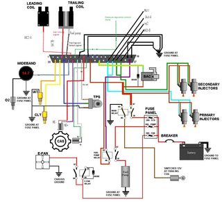
Here is the finished wiring pinout. The random wire named are the wires from the Megasquirt harness I used. I havent connected the Fuel pump wire from the pins on the DB37 since I am using a temporary kill switch. Also instead of how the wiring diagram shows the injector wires splicing into each other, I had the wires seperated to each injector. Would any of these modifications make it not start?

I followed Aaron Cakes' MS1 settings.
here is the msq
Ive finished installing the MS harness and everything wired up.
I am getting spark from rotating the CAS and seeing both leading and trailing lighting up. Im getting fuel since the sparkplug are getting wet every time.
Ive checked the timing, lining up the crank to the yellow mark, and lining up the CAS to its mark.
I dont hear the mixture igniting if you know what I mean. Its compressing the mixture during the compression stage, but its igniting it. I think the ignition timing might be off maybe, unless I am thinking too much into it. Before the Megasquirt, it ran and started fine.
Here is the finished wiring pinout. The random wire named are the wires from the Megasquirt harness I used. I havent connected the Fuel pump wire from the pins on the DB37 since I am using a temporary kill switch. Also instead of how the wiring diagram shows the injector wires splicing into each other, I had the wires seperated to each injector. Would any of these modifications make it not start?
I followed Aaron Cakes' MS1 settings.
here is the msq
Thread Starter
Joined: Nov 2002
Posts: 1,708
Likes: 6
From: Philadelphia
I also noticed that the rpm doesnt read during cranking, but when I take the leading plugs out it starts reading 250-400rpm. I find that to be weird. It doesnt read rpm when the wires and plugs are connected but reads rpm when they are both disconnected.
I forgot to also mentioned that I left the stim wheel option on when I was testing with the stimulator.
I forgot to also mentioned that I left the stim wheel option on when I was testing with the stimulator.
Thread Starter
Joined: Nov 2002
Posts: 1,708
Likes: 6
From: Philadelphia
the plug wires are stock NGK from mazdatrix, though they are about 2-3 years old. The grounds from the ecu pins I wired 4 wires to engine, and 2 to chassis.
Now that I think about it, the NE Cas wires are the stock MS shielded wire that came with the harness loom. The GE Cas wires is this http://www.diyautotune.com/catalog/w...039-p-123.html
The NE shield is grounded on pin 8 of the MS while the GE shield is grounded at the ecu frame.
I figured noise issue might be what is making my car not starting, but I wasnt 100% sure.
Should I get another shielded wire instead of using the stock one from the MS harness to run the NE?
Thread Starter
Joined: Nov 2002
Posts: 1,708
Likes: 6
From: Philadelphia
So a little update
I jerry rigged a extra CAS I had to the car attached the gear end and taped a 21mm socket to the gear and used a 3/8 cordless to spin the CAS.
With the ECU out of the car and with my testing harness plugged into it. The rpm reads fine, from a measly 70 rpm to a high 4.6krpm which is the fastest I can go with my cordless.
I reconnected the MS back into the car and into the cars harness, and used my extra CAS and wired it into the NE and GE wires in the cars harness. I attached my cordless on the CAS and spun it. It will not spark at all under 400 rpm, only sporadically. Above 400 or so RPM, it fires all the time.
Viewing the datalog, the PW, Duty cycle, and Spark angle are irratic mostly with little high rises. This is when the ECU is in the car, with the ECU out of the car and hooked up to my testing harness the datapoints are smooth.
From what I can tell, signal noise is the culprit???
You can see the log files here
out of car
http://dl.dropbox.com/u/19424277/201...20of%20car.msl
in car
http://dl.dropbox.com/u/19424277/201...20in%20car.msl
MegaSquirt Mod
Joined: Sep 2004
Posts: 4,721
Likes: 1
From: Maryland
Your grounding is not really good. You shouldn't ground both to the engine AND the chassis. That's asking for ground loops to occur.
Ground to the engine and only the engine from the MS. The stock mazda CAS wire is good too, but to go one step further, you should ground the NE and G sensors to the MS itself, and the shield to the MS itself, not the chassis. All of this is the same way Mazda did it stock.
Ken
Ground to the engine and only the engine from the MS. The stock mazda CAS wire is good too, but to go one step further, you should ground the NE and G sensors to the MS itself, and the shield to the MS itself, not the chassis. All of this is the same way Mazda did it stock.
Ken
Thread Starter
Joined: Nov 2002
Posts: 1,708
Likes: 6
From: Philadelphia
Ive rewired all my groundings to the engine. All Megasquirt grounds are at the engine at the stock places. I separated the CAS wires from the loom and brought them away from anything that can cause interference. I routed them from the passenger side all the way to the radiator support frame across the radiator and to the CAS. I did this just temporary to eliminate as much interference as I can from the CAS wires. I grounded both negative CAS and shield to the megasquirt.
I wired a dedicated power supply for the megasquirt from the battery to a relay that feeds the MS.
It still wont show a rpm until above 300 or so now.
But when I test the megasquirt on a harness adapter it is fine, so I know its not the MS itself.
I am guessing my Harness is messed up somewhere. I will tear it down and rebuild it again.
Trending Topics
Thread Starter
Joined: Nov 2002
Posts: 1,708
Likes: 6
From: Philadelphia
The MS was already built second hand.
I went over the official build instruction and Aarons instructions of the MS 3 times over making sure the built was good. It has a zeal daughterboard with one VR built. I reread and went over all the instructions on that. All the wires are hooked up to the right places on the PCB from what I can tell.
I went over the official build instruction and Aarons instructions of the MS 3 times over making sure the built was good. It has a zeal daughterboard with one VR built. I reread and went over all the instructions on that. All the wires are hooked up to the right places on the PCB from what I can tell.

Racing since u wre little
Joined: Apr 2011
Posts: 51
Likes: 0
From: Goose Creek, SC
The MS was already built second hand.
I went over the official build instruction and Aarons instructions of the MS 3 times over making sure the built was good. It has a zeal daughterboard with one VR built. I reread and went over all the instructions on that. All the wires are hooked up to the right places on the PCB from what I can tell.
I went over the official build instruction and Aarons instructions of the MS 3 times over making sure the built was good. It has a zeal daughterboard with one VR built. I reread and went over all the instructions on that. All the wires are hooked up to the right places on the PCB from what I can tell.
This is Aaron's wirirng:
http://www.aaroncake.net/RX-7/megasq..._schematic.gif
And this is yours:
http://imgur.com/WTJXl
Last edited by Gokou104; Jun 21, 2011 at 05:07 PM.
Thread Starter
Joined: Nov 2002
Posts: 1,708
Likes: 6
From: Philadelphia
^
the pin out on mines is different since the person that built it before made it like that.
Its not much of a problem since I can desolder the wire and re wire it, but I doubt its causing any problems since those pinouts are for custom wiring to your liking.
the coils are using the spr1-3 pinout, and the GE is using the IAC1A and IAC1B

Thread
Thread Starter
Forum
Replies
Last Post
trickster
2nd Generation Specific (1986-1992)
25
Jul 1, 2023 04:40 PM
alphawolff
1st Generation Specific (1979-1985)
17
Nov 17, 2015 05:57 PM