
Megasquirt DIYPNP bought, built, q's remain


Thread Starter
Full Member
Joined: Feb 2012
Posts: 153
Likes: 1
From: Tuscaloosa, AL
DIYPNP bought, built, q's remain
So I just got done building my diypnp, and was successful in uploading the ms2/msextra firmware.
Upon opening tunerstudio, I get this:
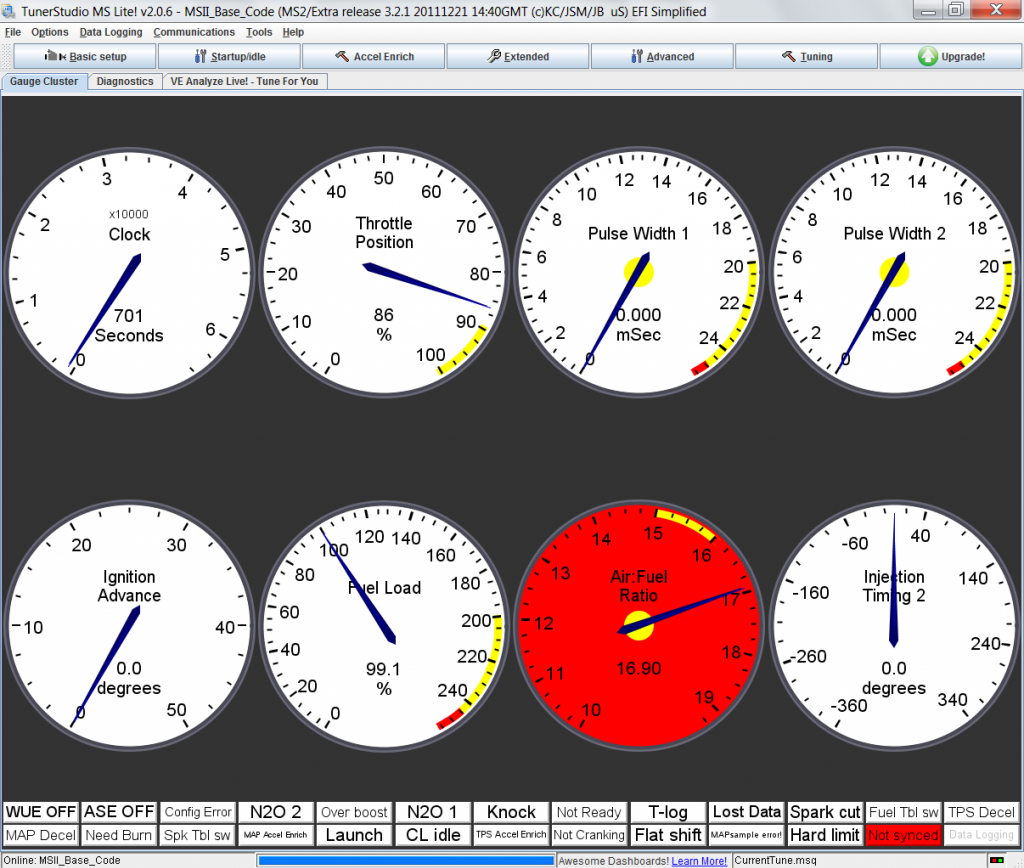
The megasquirt is sitting on my desk, powered by the power supply, and not plugged into the car or a stimulator. My question is, does anyone know why my tps is creeping up to 86% (i.e., it starts out at like ten, then creeps up to 86% and rests there) and why my fuel load is at 99%? Also, It might be the nature of the input, but if the diypnp gets no input as far as air/fuel goes, will it default to this number? I'm not sure why it's reporting that number is all. Any help is appreciated guys, I'm new at this whole megasquirt thing.
Thanks,
Jim
Upon opening tunerstudio, I get this:
The megasquirt is sitting on my desk, powered by the power supply, and not plugged into the car or a stimulator. My question is, does anyone know why my tps is creeping up to 86% (i.e., it starts out at like ten, then creeps up to 86% and rests there) and why my fuel load is at 99%? Also, It might be the nature of the input, but if the diypnp gets no input as far as air/fuel goes, will it default to this number? I'm not sure why it's reporting that number is all. Any help is appreciated guys, I'm new at this whole megasquirt thing.
Thanks,
Jim
Thread Starter
Full Member
Joined: Feb 2012
Posts: 153
Likes: 1
From: Tuscaloosa, AL
While running through sensor inputs, I'm also seeing:
Coolant temp is also a reported 180* F, while no sensor is connected.
Manifold Air Temp is reported 70*, while no sensor is connected.
I'm sure I'll come up with more questions in a bit. Thanks guys.
Coolant temp is also a reported 180* F, while no sensor is connected.
Manifold Air Temp is reported 70*, while no sensor is connected.
I'm sure I'll come up with more questions in a bit. Thanks guys.
Full Member
Joined: Dec 2005
Posts: 189
Likes: 0
From: utah
if the ms doesn't see a sensor connected it uses a default value. so it is normal to see the gauges like that with nothing connected. I am running the omp from the stock computer in piggy back. that is the only thing it does. the ms can't run the omp. with a pnpdiy you will not be able to do that though. there is a company in Australia that has a standalone omp controller.

Junior Member
Joined: Dec 2010
Posts: 21
Likes: 0
From: Atlanta
My question is, does anyone know why my tps is creeping up to 86% (i.e., it starts out at like ten, then creeps up to 86% and rests there) and why my fuel load is at 99%? Also, It might be the nature of the input, but if the diypnp gets no input as far as air/fuel goes, will it default to this number? I'm not sure why it's reporting that number is all. Any help is appreciated guys, I'm new at this whole megasquirt thing.
Thanks,
Jim
Thanks,
Jim
When the TPS input floats (is not connected), a filter cap charges and causes the reading to creep up. This is expected when bench testing without a load on the TPS input. When used in a car with a variable TPS, the input will behave normally. If used with an application that does not have a variable TPS, the input should be shorted to ground through a resistor to prevent the creeping, as it may trigger an unintended flood clear if the key is left on for a while before cranking. Otherwise there are no ill effects.
Fuel load is set to speed density (MAP vs RPM) by default. Your baro pressure must be 99kPa, which is a reasonable value.
If you have 0V on the o2 input, the o2 reading will show the 0V value. I believe that the default calibration is for a narrowband, where 1v = rich and 0v = lean. So with 0v on the input, the MegaSquirt displays the associated lean value.
Junior Member
Joined: Dec 2010
Posts: 21
Likes: 0
From: Atlanta
180� and 70� are limp home values that will automatically trigger if a sensor fault is detected. You should have some extra resistors left over from the kit. If you place one of the resistors in series between the CLT or IAT pin and ground, you will see a CLT or IAT value register. This can be done as a test if desired. Different resistors will show different values. You can see the sensor calibration data under the Tools Menu (Tools > Calibrate Thermistors)
Trending Topics
Thread Starter
Full Member
Joined: Feb 2012
Posts: 153
Likes: 1
From: Tuscaloosa, AL
You guys are awesome, thanks for that. The o2 sensor was set up for wideband at the point that photo was taken, would that make any difference?
And I will be wiring this up (jumpers, etc...) within the next week, so I will be getting back here to ask more questions more than likely. Thanks so much for everything so far.
And I will be wiring this up (jumpers, etc...) within the next week, so I will be getting back here to ask more questions more than likely. Thanks so much for everything so far.
Thread Starter
Full Member
Joined: Feb 2012
Posts: 153
Likes: 1
From: Tuscaloosa, AL
Hey guys,
I'm home now and getting it wired up, and I've got a question about the INJ1/INJ2 circuites (more q's later, but just want to tackle this right now).
I'm assuming I'd wire INJ1 to the front primary, and INJ2 to the rear primary, but what of the staged secondary injectors? Anyone?
Thanks in advance,
Jim
I'm home now and getting it wired up, and I've got a question about the INJ1/INJ2 circuites (more q's later, but just want to tackle this right now).
Originally Posted by DIYPNP site documentation
INJ1 and INJ2: These are your injector outputs. The DIYPNP is batch fire normally, so you will be using two outputs, each of which can drive one low impedance or four high impedance injectors. The INJ1 and INJ2 jumpers connect to the injector wires on the adapter board. Usually the best way to pair them is by firing order - connect the first cylinder to fire to INJ1, the second to INJ2, the third to INJ1 again, and so forth. This isn't a hard and fast rule, and some harnesses will make the injector pairing choice for you. Usually it'll run fine with pretty much any injector pairing anyway, though some pairings may be a little bit smoother.
Note that there are holes marked 3 and 4 above the INJ2 header. These are wired to the holes marked 3 and 4 in the proto area. These let you jumper a sequential add-on board to the holes in the proto area, making for fewer awkward long runs of wiring.
Note that there are holes marked 3 and 4 above the INJ2 header. These are wired to the holes marked 3 and 4 in the proto area. These let you jumper a sequential add-on board to the holes in the proto area, making for fewer awkward long runs of wiring.
Thanks in advance,
Jim
Thread Starter
Full Member
Joined: Feb 2012
Posts: 153
Likes: 1
From: Tuscaloosa, AL
I sent an email to DIY Autotune, but it being the weekend, I figured I might get a faster response here.
I'm a little unsure as to how to wire up the CAS with it's dual VR circuits. I'm going off of these two bits of info I found on ythe DIYAutotune site:
The camshaft position sensor input is marked VR2. It's actually a kind of hybrid circuit that works with Hall effect, VR, and optical sensors. Hall or optical sensors may need a pull up, just like with the crankshaft position input. VR sensors with a separate ground wire should have this wire connected to SG. The VR2 circuit has a built in threshold that some VR sensors may not trigger correctly at low RPM. If this happens on your car, take a 51K resistor and install it in the R21 position. This will lower the threshold voltage. Many Nippondenso ignitions will need this mod. For other sensors, you can install R39 to make the trigger voltage user-adjustable, or use R20 to pull up the trigger voltage to reduce noise.
NE + Red Pin 24 DB37 Pin 24 Main board pin 24
NE - White GND (pin 2 on our harness) GND (pin 2 on our harness) GND (Main board pin 2 on our harness)
G + Green Pin 25 DB15 pin 3 MS3X pin 32 (Cam input)
G - White w/ black stripe Pin 27 DB15 pin 4 Main board GND
From this, my current assumption is:
NE+ to VR+
NE- to VR-
G+ to VR2
G- to SG
Am I close?
Thanks so much for all your help, I'm getting awful close to getting this car up and running.
Thread Starter
Full Member
Joined: Feb 2012
Posts: 153
Likes: 1
From: Tuscaloosa, AL

Junior Member
Joined: Aug 2012
Posts: 13
Likes: 0
From: North Texas
I am assembling a DIYPNP system currently.... I have not found a good guild to follow, just bits and pieces from thread to thread. I understand that R21 should be 51k, but do I need to use any other pull ups (several pictures I have seen show either a 1k or 100 ohm resister in the R2 position,WLED), or any other mods for example, this thread is talking about a jumper wire from pin 11 to WDL (https://www.rx7club.com/megasquirt-f...-914072/page2/) is that necessary?
Also I have seen several threads mention a diagram for the connection from the main board to the PNP connector board but I have not seen one, anyone able to help with that?
Also I have seen several threads mention a diagram for the connection from the main board to the PNP connector board but I have not seen one, anyone able to help with that?
Junior Member
Joined: Aug 2012
Posts: 13
Likes: 0
From: North Texas
And.... do I need this thing???? Assembling the Zeal Engineering Daughterboard for MegaSquirt
Thread Starter
Full Member
Joined: Feb 2012
Posts: 153
Likes: 1
From: Tuscaloosa, AL
I've got another issue guys:
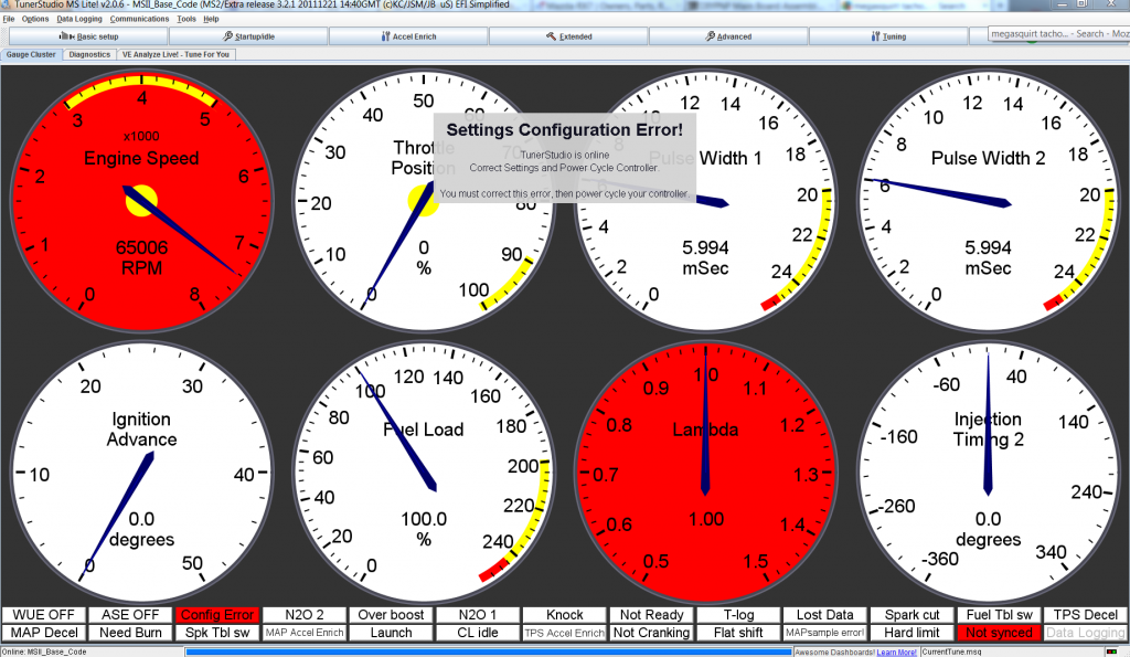
It says i've got a tacho output error. It tells me I don't need to reload the firmware, just fix some conflicting settings or something? Anyone run into this before?
It says i've got a tacho output error. It tells me I don't need to reload the firmware, just fix some conflicting settings or something? Anyone run into this before?
Thread Starter
Full Member
Joined: Feb 2012
Posts: 153
Likes: 1
From: Tuscaloosa, AL
Sorry for the triple post, but I'm just plodding away here and questions just keep popping up.
I'm not quite sure where to get a dedicated 12V source for the ECU from the stock wiring harness. The only place I see is pin 1B, which gets its power from the Main relay. My question basically boils down to then, will the main relay supply power through cranking and run position? (My assumption is yes, since this same relay circuit controls the BAC and several other solenoids)
For the fuel pump, do I need to have the ECU control it? Is it just run through the MAF, or do I need to provide a ground at the megasquirt? It looks like the stock ecu just provides a ground at the ecu, and the MAF has nothing to do with the fuel pump, but again I'm not sure.
Also, does anyone have experience with the ignition jumpers on the DIYPNP for an FC? I understand that IGN1, IGN2, and WLED will be used for leading, trailing fire, trailing select (not necessarily that order, it's on a chart somewhere...) but what jumpers do i need to put in place on the board? Like up near the DB15 connector?
Any help is appreciated guys, I'll see what I can do to keep my progress documented, if anyone would be interested in a write-up or something similar.
Thanks,
Jimmy
Joined: Feb 2001
Posts: 29,798
Likes: 128
From: London, Ontario, Canada
I would highly suggest running a new dedicated wire (fused of course) from the battery to a small aux fuse panel for the 'Squirt, from which to power anything ECU related.
For the fuel pump, run a new wire from that aux fuse panel to the pump because the stock wiring is old, crusty and undersized. Use the MS fuel pump output and a relay to switch the pump.
As for the jumpers, don't know. Never looked at the PNP. You need to enable pullups on the LEDs, so whatever jumper sets that are the jumpers you need in place.
Junior Member
Joined: Aug 2012
Posts: 13
Likes: 0
From: North Texas
Per Matt at DIY -
Pullups :
Spark output C - 100ohm in the R2 location (WLED)
put a 1N4001 diode in place of a pull up on the IAC, banded end to 12 volts
I have not tested this because I am still trying to figure out the jumper wires from the connector board to the main board, any help with that would be appreciated.
Thread Starter
Full Member
Joined: Feb 2012
Posts: 153
Likes: 1
From: Tuscaloosa, AL
I would highly suggest running a new dedicated wire (fused of course) from the battery to a small aux fuse panel for the 'Squirt, from which to power anything ECU related.
For the fuel pump, run a new wire from that aux fuse panel to the pump because the stock wiring is old, crusty and undersized. Use the MS fuel pump output and a relay to switch the pump.
As for the jumpers, don't know. Never looked at the PNP. You need to enable pullups on the LEDs, so whatever jumper sets that are the jumpers you need in place.
For the fuel pump, run a new wire from that aux fuse panel to the pump because the stock wiring is old, crusty and undersized. Use the MS fuel pump output and a relay to switch the pump.
As for the jumpers, don't know. Never looked at the PNP. You need to enable pullups on the LEDs, so whatever jumper sets that are the jumpers you need in place.
I was trying to avoid running as much new wiring as possible (sounds crazy, but all the wires in my harness have been ohmed out to less than what my analog meter will read, so I know my harness, so far, is good) and I'm not sure how to make this power switched/constant through starting.
Does the m.s. fuel pump output provide a ground or send a signal? Like for my pump relay, should I run power to the "control" side of the relay and the ground from my "control" side to the m.s.? As far as the other wiring, now might be the best time to re-do that, so might as well.
I've got most of the jumpers figured out, but I'm a bit foggy as to the ignition, as it isn't like most reciprocating piston engines you'd see elsewhere.
To reply to denverstone:
I already put the diode in the IAC pullup position, but are we providing the IAC a ground or sending a signal? The stock wiring suggests that the original configuration sent constant voltage, and the ecu would open/close a ground for it.
As for the Ignition:
100 ohm in the R2 position. Got it. Thanks!
What of the 4 jumper sets up near the db15 connector? Where we tell the ecu whether it's a 4, 6, or 8 cyl, wasted spark, COP, etc... Those jumpers are what I'm interested in. The pinout for the harness is no issue.
As for the jumper wires for the connector board, here's what I have so far, and all of the ones I have tested work. When I say not verified, I mean to say i haven't gotten readings in the software. The continuity to the plugs has checked out in all of them, 100%.
Connector Board: DIYPNP Board:
3C---------------------------O2 (not verified)
3E---------------------------CLT (not verified)
3G---------------------------TPS (software verified)
3I----------------------------VREF (software verified, used for TPS)
3L----------------------------IAT (software verified, using supplied GM sensor and spliced connector)
4A, 4B, 4D-----------------GND (continuity checked, no software to check)
4C---------------------------SG (software verified, used for TPS)
4E---------------------------VR+ (software semi-verified. Spinning the CAS by hand produces an RPM signal, and on the datalog it looks accurate.)
4H---------------------------VR - (software semi-verified, see above)
4G---------------------------VR2 (software semi-verified, see above)
4Z,4X-----------------------INJ2 (not verified, would require RPM's above the set value for staged injection. Not necessarily a big deal yet, to get the car started.)
4W,4Y----------------------INJ1 (software semi-verified, as the CAS was spun by hand, voltage spikes were registered at the injector plugs. How accurate these spikes were is unknown, I don't have an oscilloscope, but my little multimeter would spike as the CAS would spin.)
That's what I have for now. Hopefully I can get it all together within the next week or so, and I'll do a more detailed write-up.
Thanks for the help guys, I'll do my best to give back once I can say I have a working car.
Thread Starter
Full Member
Joined: Feb 2012
Posts: 153
Likes: 1
From: Tuscaloosa, AL
I'd edit that last post if I could, but A couple things to add:
I'm using an unmodified S5 N/A Harness. So if you also have an s5 n/a harness, these should work for you.
I also just tested the CLT sensor, and I get a reading in the software. So consider that verified.
I'm using an unmodified S5 N/A Harness. So if you also have an s5 n/a harness, these should work for you.
I also just tested the CLT sensor, and I get a reading in the software. So consider that verified.
Thread Starter
Full Member
Joined: Feb 2012
Posts: 153
Likes: 1
From: Tuscaloosa, AL
Post #3, but I figured I'd keep you guys updated.
I figured out where I'm going to get my power from (sorry Aaroncake, going to go through the stock harness here...)
Pin 1B to 12V
This supplies power at key position 2 and 3 (run and start). This is where the stock ECU had its power supplied, and given that I was getting a clean 12V there and this requires less modification, this is where I will be getting my power.
I'll keep putting up updates as they come, or maybe switch over to my build thread. Either or. But my other two questions (regarding Fuel Pump and IAC, providing power vs. providing ground) still stands.
Also, does anyone know if the MAF has any role in the fuel pump power circuit? my circuit diagram leads me to believe it doesn't, but if anyone else has any input here, that'd be awesome.