
12A MS2 with FC CAS and Coils- No RPM

Thread Starter

Joined: Jan 2008
Posts: 1,300
Likes: 60
From: Southfield, MI
12A MS2 with FC CAS and Coils- No RPM
Hoping i can get some help.
Ive searched and checked a lot of things based on what ive found, but still nothing.
I have a 12A BP that i was running fuel only. Recently went to FC CAS and Coils and followed Aarons writeup.
I have checked the DB37 wires to the CAS.
Pin 2 white goes to white on CAS
Pin 3 Green goes to green on CAS
Pin 4 Black goes to Black/White on CAS
Pin 24 Red goes to Red on CAS.
Ive confirmed continuity from red wire at the CAS to the Tachselect at the MS to ensure none of my connections had issues. Checks out.
I double checked the 2nd VR circuit and i was missing the ground to Spr2 and hooked that up. Checked that the chip had continuity to Ground on all the appropriate pins and that all the appropriate pins went to 5V.
Also checked that CAS line was going to Spr1 and that Out line was going to JS10.
I confirmed TSEL to VRoutInv and Tachselect to VRin.
Made sure all my resistor read the correct resistance just in case.
Read more and realized that if i dont get RPM it could be the 1st VR circuit.
Checked all the resistors and i was confused because the MS assembly guide showed one value, but the V3 board schematic showed a different value. My resistors all matched the Assembly guide, although R42 and R55 read 630 ohms instead of 1k. Thats outside of the 20% tolerance so i dont know if that would cause the issue.
Dont really know how to check the transistors or the U7 chip. I only made sure you could read the correct resistance values from the chip leg to the closest resistor.
Turned the pots counter clockwise, R52, i heard the click and had no issues. I also read between leg 1 and 3 and it read close to the 100k value. R56 i was never able to hear a click or indent to really set it.
Also measured between legs 1 and 3 and was only able to read .56K and not the 10K it says in the print. Value did not change regardless of how i moved the screw. Dont know if that could be the issue or not.
Lastly, I dont know how to test the CAS and i dont know if it functioned, as i got it second hand. i measured continuity across the respective pins for the top and the bottom pickups and they both measured the same so i am assuming the CAS is ok.
Any help is appreciated, i am out of ideas on where to go from here. I crank and the rpm remains at zero.
I tried to record a composite log, but it just says the reading is empty.
Attached is my tune, maybe i set something wrong in there.
Thanks.

Senior Member
Joined: Nov 2006
Posts: 474
Likes: 16
From: connecticut
i would advice you to get a dual vr conditioner from jbperf.com or something similar way easier and trouble free.also which ms are you using.
Last edited by elturbonitroso; Feb 16, 2020 at 05:57 PM.
Thread Starter
Joined: Jan 2008
Posts: 1,300
Likes: 60
From: Southfield, MI
Originally Posted by elturbonitroso
i would advice you to get a dual vr conditioner from jbperf.com or something similar way easier and trouble free.also which ms are you using.
I am using ms2. I'll look into the jbperf one if I can't get this functioning. I am going to pick up an oscilloscope from a friend tonight and hope it gives me a little more insight into what's going on. Best case scenario is the CAS is bad and it's actually not putting out a signal.
Thread Starter
Joined: Jan 2008
Posts: 1,300
Likes: 60
From: Southfield, MI
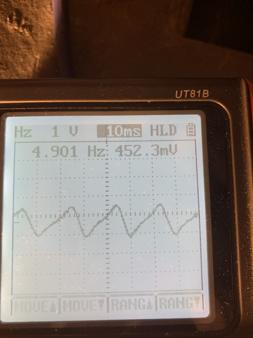
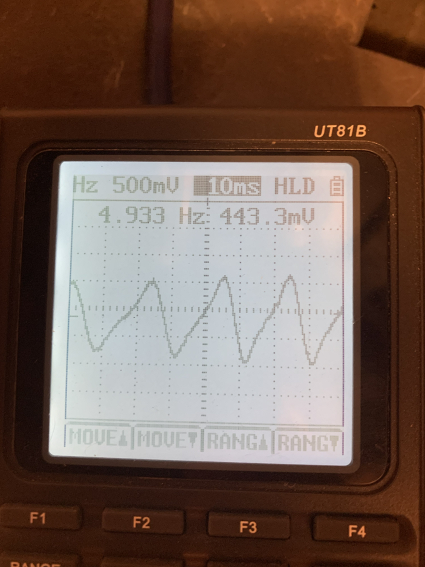
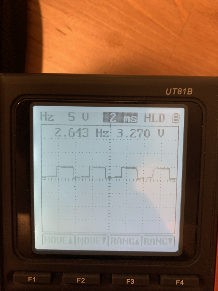
Go the oscilloscope and tested the CAS alone. Perfect AC wave.
Continued back the wire to my breakout board.
Perfect AC wave
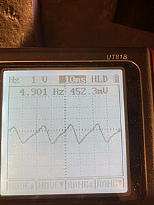
Continued to the db37 and perfect AC wave.
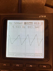
So this must mean it's the 1st VR circuit.
Can someone point me to how to test the vr circuit or where do I probe the ecm to check for functionality with the oscope?
Thanks.
Continued back the wire to my breakout board.
Perfect AC wave
Continued to the db37 and perfect AC wave.
So this must mean it's the 1st VR circuit.
Can someone point me to how to test the vr circuit or where do I probe the ecm to check for functionality with the oscope?
Thanks.
Thread Starter
Joined: Jan 2008
Posts: 1,300
Likes: 60
From: Southfield, MI
I think my u7 chip is toast.
I plugged the stim and pin 2 of u7 I can see a clean square wave coming from the stim.
I can turn the rpm potentiometer and see the wave change from 155 hz to 355 hz and also go flat line when I go to zero rpm.

Now when I check on pin 1 or pin 3, all I see is a flat lined voltage.
I am assuming pin 1 should also be outputting a wave similar to the stims square wave since the stim is a perfect square wave and the point of the chip is to output a square wave to the processor.
This would mean that my u7 is toast, right?
Any feedback here is appreciated. If I don't hear back then I'll just go and buy a new u7 chip and replace it. Would like some confirmation before though.
Thanks.
I plugged the stim and pin 2 of u7 I can see a clean square wave coming from the stim.
I can turn the rpm potentiometer and see the wave change from 155 hz to 355 hz and also go flat line when I go to zero rpm.
Now when I check on pin 1 or pin 3, all I see is a flat lined voltage.
I am assuming pin 1 should also be outputting a wave similar to the stims square wave since the stim is a perfect square wave and the point of the chip is to output a square wave to the processor.
This would mean that my u7 is toast, right?
Any feedback here is appreciated. If I don't hear back then I'll just go and buy a new u7 chip and replace it. Would like some confirmation before though.
Thanks.
Senior Member
Joined: Nov 2006
Posts: 474
Likes: 16
From: connecticut
just buy this and save your self a headache https://www.ebay.com/itm/Dual-VR-con...sAAOSwPzhaM4ow
Trending Topics
Thread Starter
Joined: Jan 2008
Posts: 1,300
Likes: 60
From: Southfield, MI
Originally Posted by elturbonitroso
just buy this and save your self a headache https://www.ebay.com/itm/Dual-VR-con...sAAOSwPzhaM4ow
I'll keep this in mind if I completely hit a brick wall with figuring this out. It's frustrating but it also pushes me to learn more of the circuit functionality.
Do you know happen to know the answer to my last question? Thanks.
Thread Starter
Joined: Jan 2008
Posts: 1,300
Likes: 60
From: Southfield, MI
Now I am doubting myself if the u7 op amp is bad or not. Considering that the input from the stim is a standard sq wave, the op amp would not see a negative voltage and therefore only put out a flat line voltage?
I just bought a Jim stim since I only had the standard stim so I can simulate an actual VR and see what the op amp outputs before I buy another one. I guess I should have bought a Jim stim a long time ago.
I just bought a Jim stim since I only had the standard stim so I can simulate an actual VR and see what the op amp outputs before I buy another one. I guess I should have bought a Jim stim a long time ago.
Thread Starter
Joined: Jan 2008
Posts: 1,300
Likes: 60
From: Southfield, MI
Got the Jim stim. Signal into pin 2 of u7 looked good, but signal out of pin 1 was just a flat line voltage again. Checked the trim pots and they change resistance as I turn them, but still got nothing out of pin 1.
I changed u7 and q22 and 23 and no difference.
I checked all the VCC lines and they had 4.96V.
I setup TunerStudio just like Aaron says in his write up so I don't think I did anything wrong there.
Any suggestion is appreciated. I am out of ideas of what it could be.
Thanks.
I changed u7 and q22 and 23 and no difference.
I checked all the VCC lines and they had 4.96V.
I setup TunerStudio just like Aaron says in his write up so I don't think I did anything wrong there.
Any suggestion is appreciated. I am out of ideas of what it could be.
Thanks.
Thread Starter
Joined: Jan 2008
Posts: 1,300
Likes: 60
From: Southfield, MI
Posting this in case someone else might be looking. I think I determined the problem.
My q23 showed continuity between legs 3 and 2. I removed the transistor and measured continuity on the pads and they are shorted together. There is no solder bridging so I am assuming the issue the pads are bridged within the pcb somehow. I will do an external wiring of the transistor and bypassing the solder pads to test if it solves the problem. Will report back.
My q23 showed continuity between legs 3 and 2. I removed the transistor and measured continuity on the pads and they are shorted together. There is no solder bridging so I am assuming the issue the pads are bridged within the pcb somehow. I will do an external wiring of the transistor and bypassing the solder pads to test if it solves the problem. Will report back.
Senior Member
Joined: Nov 2006
Posts: 474
Likes: 16
From: connecticut
that may be your problem,and i dont want to sound like an *** but i already told you the solution of your problem when im doing nippodenso CAS i always use the jbperf board or something similar and never have problems.
Thread Starter
Joined: Jan 2008
Posts: 1,300
Likes: 60
From: Southfield, MI
Originally Posted by elturbonitroso
that may be your problem,and i dont want to sound like an *** but i already told you the solution of your problem when im doing nippodenso CAS i always use the jbperf board or something similar and never have problems.
Senior Member
Joined: Nov 2006
Posts: 474
Likes: 16
From: connecticut
I don't disagree. At this point I will buy the jbperf board since I can't fix the actual pcb. This is also a learning experience to better understand the circuit, what the ms is doing and so on. If I just bought the jb board and didn't trouble shoot it, I didn't learn anything.

Senior Member
Joined: Nov 2003
Posts: 295
Likes: 6
From: Mich. USA
Posting this in case someone else might be looking. I think I determined the problem.
My q23 showed continuity between legs 3 and 2. I removed the transistor and measured continuity on the pads and they are shorted together. There is no solder bridging so I am assuming the issue the pads are bridged within the pcb somehow. I will do an external wiring of the transistor and bypassing the solder pads to test if it solves the problem. Will report back.
My q23 showed continuity between legs 3 and 2. I removed the transistor and measured continuity on the pads and they are shorted together. There is no solder bridging so I am assuming the issue the pads are bridged within the pcb somehow. I will do an external wiring of the transistor and bypassing the solder pads to test if it solves the problem. Will report back.
Sheet 3 of 8 is where I'm referencing.
V3 Main Board
Thread Starter
Joined: Jan 2008
Posts: 1,300
Likes: 60
From: Southfield, MI
I'm a dig through the circuits kinda mindset kinda person myself. Q23 pin 3 is gnd, pin 2 is connected to the wiper of R56. If you have continuity to ground on pin 2 you may have a bad R56 pot, and not a board short. Do the ohms change from pins 1 to 2 on R56 when you turn it?
Sheet 3 of 8 is where I'm referencing.
V3 Main Board
Sheet 3 of 8 is where I'm referencing.
V3 Main Board
i did check voltage from pin 1 to pin 2 and from 2 to 3 there is a constant 4.96V then as i turn the pot, you can see the voltage changing, which is why i assumed R56 was ok.
Maybe i can desolder the R56 pot and maybe check Q23 pads again? What do you think?
Senior Member
Joined: Nov 2003
Posts: 295
Likes: 6
From: Mich. USA
Q23 pad 2 will show continuity to ground (Q23 pad 3) if R56 is fully CCW because the pot wiper is essentially fully biased toward the grounded side of the variable resistor. Double check that you are getting varying voltage on R56/Q23 pin 2 and set it to ~1V and test again with the stim and scope the U7A output.
Thread Starter
Joined: Jan 2008
Posts: 1,300
Likes: 60
From: Southfield, MI
So i bought the JBPerf Dual VR. I just installed it. I installed it as follows
VR1+ = TachSelect
VR1- = Pin 5 (Spr3) on DB37
VR2+ = Pin 3 (Spr1) on Db37
VR2- = Pin 4 (Spr2) on DB37
Out1 = Tsel
Out2 = JS10
The part that i am confused on is how to setup the Jimstim to send VR1- to Spr3.
Would appreciate the help.
VR1+ = TachSelect
VR1- = Pin 5 (Spr3) on DB37
VR2+ = Pin 3 (Spr1) on Db37
VR2- = Pin 4 (Spr2) on DB37
Out1 = Tsel
Out2 = JS10
The part that i am confused on is how to setup the Jimstim to send VR1- to Spr3.
Would appreciate the help.
Thread Starter
Joined: Jan 2008
Posts: 1,300
Likes: 60
From: Southfield, MI
I plugged it into the car and still no rpms.
I used the oscope and signals going to the dual vr are good both going in and out from both out 1 and out 2.
I am really frustrated with this.
The only other thing would be the actual cpu, but I am truly tired of spending money and not getting anywhere.
If I put the oscope on the cpu pin for pin 24 and is ok I would assume it would have to be the cpu, right?
I am really close to just scrapping it, selling the tbi and going back to carb.
Thread Starter
Joined: Jan 2008
Posts: 1,300
Likes: 60
From: Southfield, MI
Negative probe on the vr1- input signal, spr3 and positive probe on pin 14 of the daughter board. Signal into it was clean. So I am assuming the channel must have fried somehow when I was having tach spikes when running the distributor. I am going to swap in another daughter board that I have. Let's see if that one helps. Although I swapped that one because at some point I thought it was bad. But I am out of ideas.
Thread Starter
Joined: Jan 2008
Posts: 1,300
Likes: 60
From: Southfield, MI
Originally Posted by elturbonitroso
you must have a wiring problem somewhere or a setting problem.