
HOW TO: Galaxy 7" Pad Install - Stereo, Gauges, GPS, and more....


Thread Starter
Eats, Sleeps, Dreams Rotary
iTrader: (52)
Joined: Oct 2001
Posts: 3,902
Likes: 10
From: NJ
HOW TO: Galaxy 7" Pad Install - Stereo, Gauges, GPS, and more....
OVERVIEW
I have been wanting to do this write-up for awhile. I posted it in the FD section, but wanted to put it here as well. I recently installed my 7" Samsung Galaxy pad in my dash as a functioning stereo. Of course, like all Android devices, there is a lot of flexibility for other uses. Below, I will layout what I used to install the pad, and what functions I am using with it installed. Finally, I will go over a few of the challenges and options others may choose to do differently.
I chose to install the pad mostly because of the App that was created for my Adaptronic ECU. Adaptive Tuner allows users to link their device to the ECU via bluetooth and view engine metrics, electronic gauges, adaptive tuning flags, and now to edit the fuel map itself. With a little research and looking on Youtube, I saw that Pad installs were not only becoming common, but seem to be in full swing in the automotive world. So I devised a plan...
FUNCTIONS
1. Adaptive Tuner - As mentioned, Adaptive tuner is a flexible App developed for Android devices. I will not go into the full functions of the App, but I will post the link of the thread on the Adaptronic forum. This thread has lots information on installing, and linking the device to the ECU. I will outline exactly how I did it further in the write-up. Login
2. Stereo - Using a Clarion amplifier, and some other wiring I could use the Pad as an effective stereo. I chose to run the App WinAmp. This has a nice equalizer, and also can link to my PC to transfer songs to the Pad. Using the Pad as a stereo has its challenges, mostly with volume control. I chose to install an external volume control **** for quick use.
3. GPS, and Internet - Many Pads have the 3G data plan option. My Galaxy is limited to Wifi, but using my cell phone to tether, it automatically links and pulls data this way. Google maps, GPS, and internet functions work on the go. In the future, I may switch to a stand alone 3G option, but I have had no issues with tethering currently.
INSTALLATION
Install Parts
(1) 7" Pad of your choice - I chose my Galaxy Pad
(1) Amplifier of your choice - I chose a small Clarion 4 channel
(1) Mazda Rx7 aftermarket stereo wiring harness
(2) Universal metal stereo install strips
(1) 3.5mm audio to RCA cable - a 90 degree on the 3.5mm side is needed
(2) RCA "Y" cables - male on all 3 sides
(1) RCA Amplifier Volume Control box
(1) 12v cigarette terminal
(1) 12v charger for Pad
Adaptive Tuner Parts
(1) Innovative RS232 to serial
(1) RS232 DB9 blue tooth dongle
(1) 5V power source - I chose the Innovative TC-4 EGT. Others have wired in a 12v to 5v regulator
Pad Install
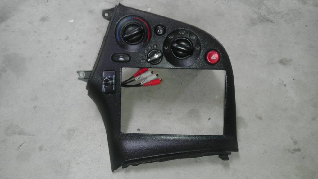
1. You will need to remove the steering column suround and pull the gauge hood and cluster out. This must be done to remove the outer skin of the double DIN pocket. This outer skin holds the heater controls and hazard light buttons as well. Be sure to remove the connectors from the skin when you pull it off. Once out, you will see the inner frame of the DIN pocket. You will also need to remove the center console below the shifter. Once the **** is off, it pops right off. For those with untouched cars, there is often a separator for the stereo that runs across the pocket. This was already cut out on my car. Simply use a Dremel tool to remove the plastic separator.
The skin that needs removed.
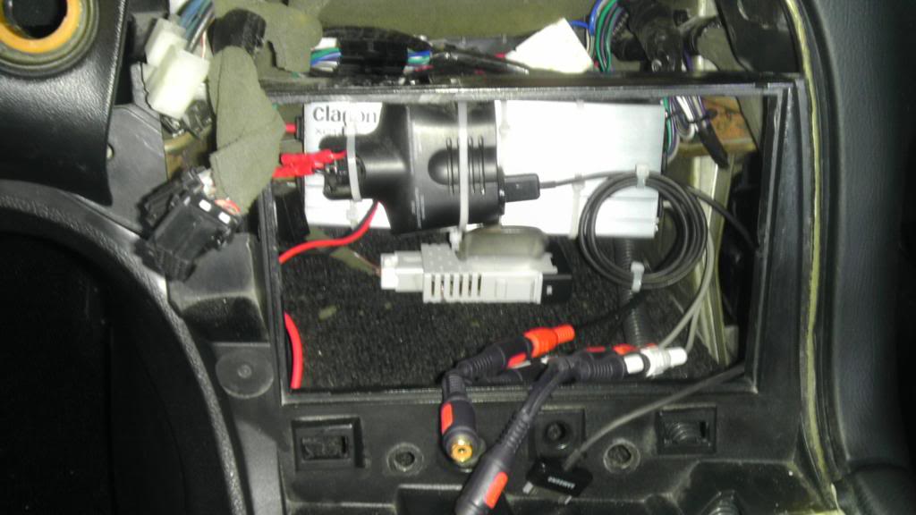
You will be left with this. (picture taken after amplifier was installed)
2. With the skin removed test fit the pad in the pocket. It should fit very flush. All Pads are a little different but most have the power and volume buttons on the upper right side. I chose to point these buttons upward as I turned the top of the Pad to the left. Of course, when the Pad is pushed up into place, the buttons hit the DIN frame. You will need to take a dremel and slot out a space for the buttons to sit. This allows the Pad to sit firmly in the frame without the buttons being affected.
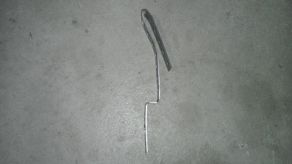
3. Now that the Pad can be pushed up to the frame, and the screen sits flush to the DIN frame, we need to hold the Pad securely. I used 2 universal stereo mounting brackets and bent them into shape. You will see that when bending I created a flat piece for the bottom of the pad to sit on, and then bent the top of the bracket inward to hold the top of the Pad in place. These can be purchased at any audio store, Walmart, or Crutchfield. They are identifiable by the perforated holes throughout. I bent them like so.
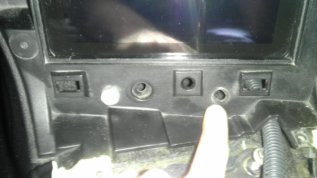
4. Now I had to drill a hole to mount the bottom of the brackets in place. The lower portion of the DIN frame is unused, and does not affect how the center console snaps down. I drilled 2 evenly spaced holes across the bottom of the DIN frame. These holes will be used to mount the bottom of the brackets, and hold the Pad into place.
5. Test fit the Pad. It will take a few tries to get it to fit correctly and for the brackets to hold the pad down tight. You may have to bend the brackets to get everything flush and snug. Take your time! I recommend covering the face of the pad with painters tape. This helps protect the screen as you pull it in and out to get things perfect.
Amp Install
1. There are many options here. Some folks could mount the amplifier in the rear of the car and run the cables to the front, or mount it in the stereo pocket itself. I chose a compact amplifier that I could mount inside the stereo pocket itself. It zip tied securely to the rear metal frame in the DIN pocket.
Clarion U.S.A. | XC1410
2. This amplifier is a 4 channel and has both RCA and traditional wires for both input and output. This was perfect for driving my 4 Infinity speakers in the stock location. I simply used an Rx7 aftermarket wiring harness and wired the amp's output to it. A note on wiring, the aftermarket harness does have a blue remote wire. This wire did not effectively turn on the amp when I switched the key on. Because the switched power wire (red) was available, I used this to trigger the amp on with the key. For power, I ran a 10 gauge wire from the battery. There was a large factory 10 gauge ground already in the stereo compartment that grounded to the metal frame. I used it for grounding.
Audio Wiring
From the parts list it is pretty easy to see how I got the Pads 3.5mm audio to input to the amplifier. It is as follows...
PAD > 3.5mm to two RCAs > RCA Volume Control **** > (2) "Y" splitters > AMP RCA INPUT
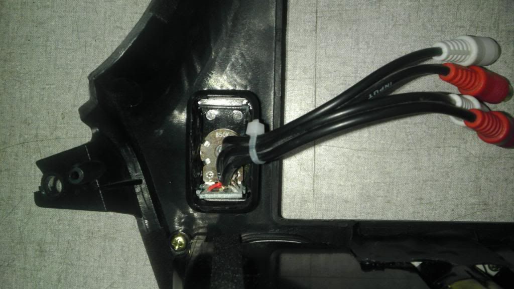
Volume Control
1. I wanted to control the volume with an actual ****. Electronic control works, but it can be cumbersome for situations when you need silence immediately. I chose the PAC LC1.

2. There are many different ways to do this. I wanted a clean install with an OEM look. I chose to install the **** where the dimmer switch was. I NEVER used the dimmer switch as I always liked my interior lighting turned up. All I did was unplug the switch from the pocket, and mounted it below the amp. This left the pocket open to mount my ****.
3. I could not find a **** to perfectly fit the pocket. The **** I listed above was pretty small and universal in nature. Furthermore, the 3.5mm audio jack stuck out JUST enough to prevent me from putting either the dimmer, or the volume box in. Easy fix, I took a dremel and chopped up the volume box. I kept the face piece that the internal electronics mounted to, and I epoxied it over the hole. This allowed the slender electronic portion to fit in the hole, and still look clean.
Pad Power
1. Powering and charging the Pad is very straightforward. Using a universal 12v female plug, I wired in to switched power and ground. I then used a 12V plug made for my Pad, and it was good to go.
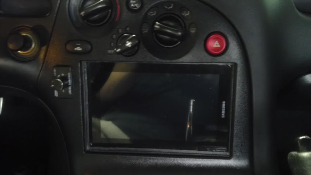
Finalized Install
CONTROL
I downloaded an App called "Tasker". This App is very flexible. It allows your Android device to respond to certain events. This way, when the App senses 12v input from turning on the key, I can turn on the screen, take it out of airplane mode, and link to the ECU through blue tooth. The same is true when the key is turned off. Back to airplane mode, and shutting down the screen. Overall an effective tool.
ADAPTIVE TUNER
1. I finally received the Innovative LC-1 wideband and TC-4 thermocoupler so it came time to wire up the ECU, Bluetooth dongle, and get everything talking with the App. The blue tooth dongle I purchased was pretty nice. Its a nice setup as it includes an exterior plug in harness for 5v power. No soldering the pins for power. It also has a master/slave switch, DCE/DTE, and a mini USB for power (if wanted) all built in. The documentation is pretty thorough as well. It shows the commands for setting it up in a computer program called hyperterminal, which is essential to get the device set to the proper speed of 57600.
Bluetooth Serial Adapter RS232
2. Using this with a male to male DB9 gender bender, allowed me to plug it into my Innovative DB9 to serial cable (2.5mm). This 2.5mm plugs into the Adaptronic ECU's output serial port.
3. The Innovative TC-4 (EGT box) has a feature of 5v output power for external sensors. With this, It was easy to just mount the donlge to the TC-4, and wire it up.
4. The Blue Tooth dongle by default uses a 19200 baud connection speed, as indicated in the instructions. All I needed to do was connect the dongle to my computers serial port, give it power via the supplied USB cable, and use Hyper Terminal to change it. Since my computer is Windows 7, Hyper Terminal is not supplied, so I had to go online and find it. Once connected, I had to change the speed and settings to match the following.
<<<=Y (to enable command inputs)
BAUD=57600
PARITY= N
STOP=1
FLOW=N
5. Remember that once you change the speed on the dongle, you will lose connectivity in Hyper Terminal, and must go into the settings and change your 19200 speed to the new 57600. You can then continue with the rest of the settings. As mentioned, the commands are included in the BT dongles instructions. There are quite a few commands that aren't needed but can be handy to use; changing the dongles default pairing PIN, and so forth. All of these are done through the Hyper Terminal.
6. As I mentioned before, the dongle itself has a few physical switches on it. Below are what I chose and what I got to work.
DTE/DCE Switch = DTE
G/NG Switch = G
Batt/USB = USB (you can use either here. I chose to strip down a USB cable and wire them for the 5V. You can also use the supplied harness for the 5v, but it seemed more fragile)
Master/Slave = Slave
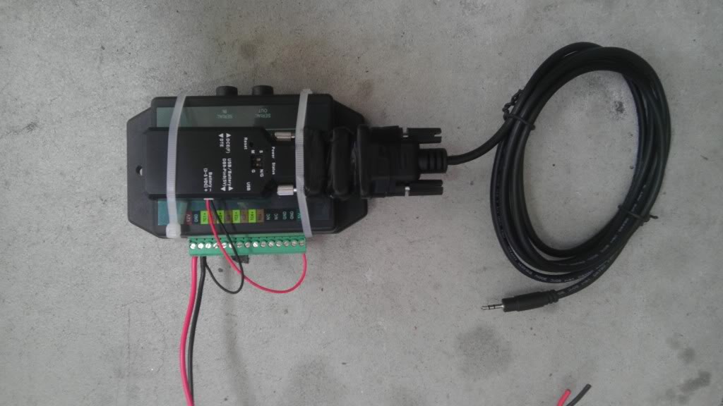
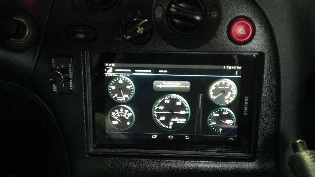
7. Once squared away, my Pad with the Adaptive Tuner App could pair with the BT dongle, and see the ECU data. I have been looking forward to this for awhile, and now I get to see a few metrics in action. Granted, my engine bay is still not complete, but I can view a few things actively.
The Innovative TC4, Bluetooth dongle, and DB9 to serial
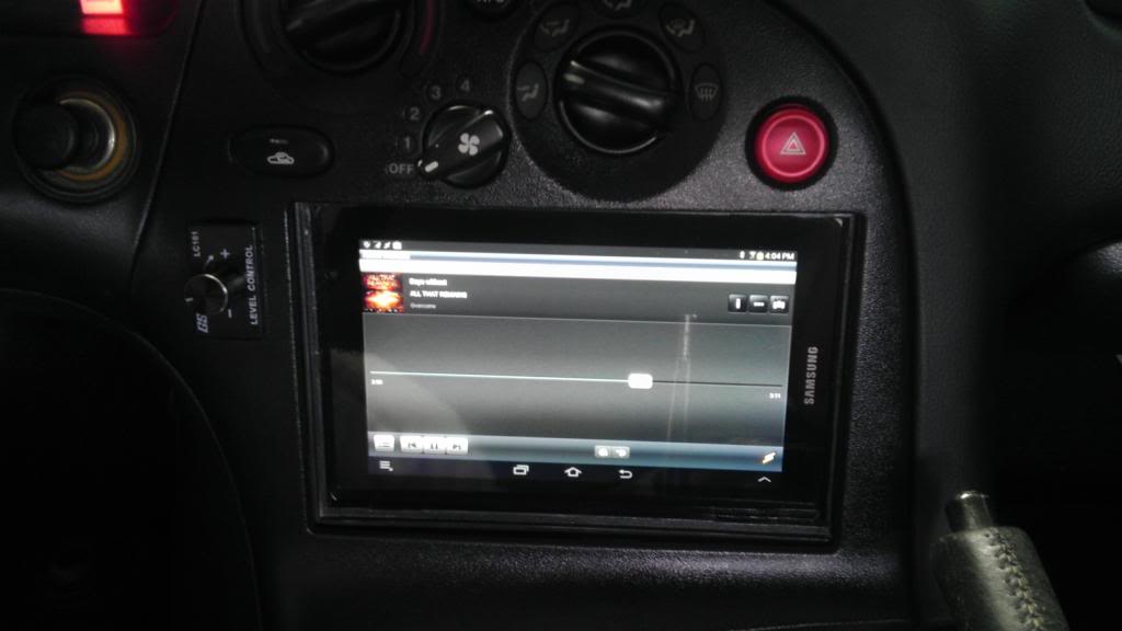
Running the App and linked to the ECU
FINAL THOUGHTS
Overall, a success. There are a few issues that I have outlined in video form below. The inability to access the Pad's power buttons can be an issue. If the OS were to freeze, it would need booted by the button itself. Furthermore, the pad must maintain a charge. It does well in airplane mode with the screen off, but extended periods would cause the Pad to shutdown. Ideally, a remote mounting of the power button is in order.
Also, I need a final trim piece. The end result looks nice, but it could look better. A flush trim piece would help the overall finish of the install. I have been looking at options and plan to do this as well.
I hope this helps some folks out there with similar ideas. There are many ways to do this type of thing, but this is what I chose.
Thanks
I have been wanting to do this write-up for awhile. I posted it in the FD section, but wanted to put it here as well. I recently installed my 7" Samsung Galaxy pad in my dash as a functioning stereo. Of course, like all Android devices, there is a lot of flexibility for other uses. Below, I will layout what I used to install the pad, and what functions I am using with it installed. Finally, I will go over a few of the challenges and options others may choose to do differently.
I chose to install the pad mostly because of the App that was created for my Adaptronic ECU. Adaptive Tuner allows users to link their device to the ECU via bluetooth and view engine metrics, electronic gauges, adaptive tuning flags, and now to edit the fuel map itself. With a little research and looking on Youtube, I saw that Pad installs were not only becoming common, but seem to be in full swing in the automotive world. So I devised a plan...
FUNCTIONS
1. Adaptive Tuner - As mentioned, Adaptive tuner is a flexible App developed for Android devices. I will not go into the full functions of the App, but I will post the link of the thread on the Adaptronic forum. This thread has lots information on installing, and linking the device to the ECU. I will outline exactly how I did it further in the write-up. Login
2. Stereo - Using a Clarion amplifier, and some other wiring I could use the Pad as an effective stereo. I chose to run the App WinAmp. This has a nice equalizer, and also can link to my PC to transfer songs to the Pad. Using the Pad as a stereo has its challenges, mostly with volume control. I chose to install an external volume control **** for quick use.
3. GPS, and Internet - Many Pads have the 3G data plan option. My Galaxy is limited to Wifi, but using my cell phone to tether, it automatically links and pulls data this way. Google maps, GPS, and internet functions work on the go. In the future, I may switch to a stand alone 3G option, but I have had no issues with tethering currently.
INSTALLATION
Install Parts
(1) 7" Pad of your choice - I chose my Galaxy Pad
(1) Amplifier of your choice - I chose a small Clarion 4 channel
(1) Mazda Rx7 aftermarket stereo wiring harness
(2) Universal metal stereo install strips
(1) 3.5mm audio to RCA cable - a 90 degree on the 3.5mm side is needed
(2) RCA "Y" cables - male on all 3 sides
(1) RCA Amplifier Volume Control box
(1) 12v cigarette terminal
(1) 12v charger for Pad
Adaptive Tuner Parts
(1) Innovative RS232 to serial
(1) RS232 DB9 blue tooth dongle
(1) 5V power source - I chose the Innovative TC-4 EGT. Others have wired in a 12v to 5v regulator
Pad Install
1. You will need to remove the steering column suround and pull the gauge hood and cluster out. This must be done to remove the outer skin of the double DIN pocket. This outer skin holds the heater controls and hazard light buttons as well. Be sure to remove the connectors from the skin when you pull it off. Once out, you will see the inner frame of the DIN pocket. You will also need to remove the center console below the shifter. Once the **** is off, it pops right off. For those with untouched cars, there is often a separator for the stereo that runs across the pocket. This was already cut out on my car. Simply use a Dremel tool to remove the plastic separator.
The skin that needs removed.

You will be left with this. (picture taken after amplifier was installed)

2. With the skin removed test fit the pad in the pocket. It should fit very flush. All Pads are a little different but most have the power and volume buttons on the upper right side. I chose to point these buttons upward as I turned the top of the Pad to the left. Of course, when the Pad is pushed up into place, the buttons hit the DIN frame. You will need to take a dremel and slot out a space for the buttons to sit. This allows the Pad to sit firmly in the frame without the buttons being affected.
3. Now that the Pad can be pushed up to the frame, and the screen sits flush to the DIN frame, we need to hold the Pad securely. I used 2 universal stereo mounting brackets and bent them into shape. You will see that when bending I created a flat piece for the bottom of the pad to sit on, and then bent the top of the bracket inward to hold the top of the Pad in place. These can be purchased at any audio store, Walmart, or Crutchfield. They are identifiable by the perforated holes throughout. I bent them like so.

4. Now I had to drill a hole to mount the bottom of the brackets in place. The lower portion of the DIN frame is unused, and does not affect how the center console snaps down. I drilled 2 evenly spaced holes across the bottom of the DIN frame. These holes will be used to mount the bottom of the brackets, and hold the Pad into place.

5. Test fit the Pad. It will take a few tries to get it to fit correctly and for the brackets to hold the pad down tight. You may have to bend the brackets to get everything flush and snug. Take your time! I recommend covering the face of the pad with painters tape. This helps protect the screen as you pull it in and out to get things perfect.
Amp Install
1. There are many options here. Some folks could mount the amplifier in the rear of the car and run the cables to the front, or mount it in the stereo pocket itself. I chose a compact amplifier that I could mount inside the stereo pocket itself. It zip tied securely to the rear metal frame in the DIN pocket.
Clarion U.S.A. | XC1410
2. This amplifier is a 4 channel and has both RCA and traditional wires for both input and output. This was perfect for driving my 4 Infinity speakers in the stock location. I simply used an Rx7 aftermarket wiring harness and wired the amp's output to it. A note on wiring, the aftermarket harness does have a blue remote wire. This wire did not effectively turn on the amp when I switched the key on. Because the switched power wire (red) was available, I used this to trigger the amp on with the key. For power, I ran a 10 gauge wire from the battery. There was a large factory 10 gauge ground already in the stereo compartment that grounded to the metal frame. I used it for grounding.
Audio Wiring
From the parts list it is pretty easy to see how I got the Pads 3.5mm audio to input to the amplifier. It is as follows...
PAD > 3.5mm to two RCAs > RCA Volume Control **** > (2) "Y" splitters > AMP RCA INPUT
Volume Control
1. I wanted to control the volume with an actual ****. Electronic control works, but it can be cumbersome for situations when you need silence immediately. I chose the PAC LC1.
2. There are many different ways to do this. I wanted a clean install with an OEM look. I chose to install the **** where the dimmer switch was. I NEVER used the dimmer switch as I always liked my interior lighting turned up. All I did was unplug the switch from the pocket, and mounted it below the amp. This left the pocket open to mount my ****.
3. I could not find a **** to perfectly fit the pocket. The **** I listed above was pretty small and universal in nature. Furthermore, the 3.5mm audio jack stuck out JUST enough to prevent me from putting either the dimmer, or the volume box in. Easy fix, I took a dremel and chopped up the volume box. I kept the face piece that the internal electronics mounted to, and I epoxied it over the hole. This allowed the slender electronic portion to fit in the hole, and still look clean.

Pad Power
1. Powering and charging the Pad is very straightforward. Using a universal 12v female plug, I wired in to switched power and ground. I then used a 12V plug made for my Pad, and it was good to go.
Finalized Install


CONTROL
I downloaded an App called "Tasker". This App is very flexible. It allows your Android device to respond to certain events. This way, when the App senses 12v input from turning on the key, I can turn on the screen, take it out of airplane mode, and link to the ECU through blue tooth. The same is true when the key is turned off. Back to airplane mode, and shutting down the screen. Overall an effective tool.
ADAPTIVE TUNER
1. I finally received the Innovative LC-1 wideband and TC-4 thermocoupler so it came time to wire up the ECU, Bluetooth dongle, and get everything talking with the App. The blue tooth dongle I purchased was pretty nice. Its a nice setup as it includes an exterior plug in harness for 5v power. No soldering the pins for power. It also has a master/slave switch, DCE/DTE, and a mini USB for power (if wanted) all built in. The documentation is pretty thorough as well. It shows the commands for setting it up in a computer program called hyperterminal, which is essential to get the device set to the proper speed of 57600.
Bluetooth Serial Adapter RS232
2. Using this with a male to male DB9 gender bender, allowed me to plug it into my Innovative DB9 to serial cable (2.5mm). This 2.5mm plugs into the Adaptronic ECU's output serial port.
3. The Innovative TC-4 (EGT box) has a feature of 5v output power for external sensors. With this, It was easy to just mount the donlge to the TC-4, and wire it up.
4. The Blue Tooth dongle by default uses a 19200 baud connection speed, as indicated in the instructions. All I needed to do was connect the dongle to my computers serial port, give it power via the supplied USB cable, and use Hyper Terminal to change it. Since my computer is Windows 7, Hyper Terminal is not supplied, so I had to go online and find it. Once connected, I had to change the speed and settings to match the following.
<<<=Y (to enable command inputs)
BAUD=57600
PARITY= N
STOP=1
FLOW=N
5. Remember that once you change the speed on the dongle, you will lose connectivity in Hyper Terminal, and must go into the settings and change your 19200 speed to the new 57600. You can then continue with the rest of the settings. As mentioned, the commands are included in the BT dongles instructions. There are quite a few commands that aren't needed but can be handy to use; changing the dongles default pairing PIN, and so forth. All of these are done through the Hyper Terminal.
6. As I mentioned before, the dongle itself has a few physical switches on it. Below are what I chose and what I got to work.
DTE/DCE Switch = DTE
G/NG Switch = G
Batt/USB = USB (you can use either here. I chose to strip down a USB cable and wire them for the 5V. You can also use the supplied harness for the 5v, but it seemed more fragile)
Master/Slave = Slave
7. Once squared away, my Pad with the Adaptive Tuner App could pair with the BT dongle, and see the ECU data. I have been looking forward to this for awhile, and now I get to see a few metrics in action. Granted, my engine bay is still not complete, but I can view a few things actively.
The Innovative TC4, Bluetooth dongle, and DB9 to serial

Running the App and linked to the ECU

FINAL THOUGHTS
Overall, a success. There are a few issues that I have outlined in video form below. The inability to access the Pad's power buttons can be an issue. If the OS were to freeze, it would need booted by the button itself. Furthermore, the pad must maintain a charge. It does well in airplane mode with the screen off, but extended periods would cause the Pad to shutdown. Ideally, a remote mounting of the power button is in order.
Also, I need a final trim piece. The end result looks nice, but it could look better. A flush trim piece would help the overall finish of the install. I have been looking at options and plan to do this as well.
I hope this helps some folks out there with similar ideas. There are many ways to do this type of thing, but this is what I chose.
Thanks

Thread
Thread Starter
Forum
Replies
Last Post
diabolical1
2nd Generation Specific (1986-1992)
30
Jan 30, 2016 05:50 AM