
Haltech ls1 coils to e6k


Originally Posted by GUITARJUNKIE28
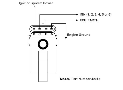
here ya go
careful with the coil charge time. i roasted a set of leading coils when i was running them in wastespark mode.
careful with the coil charge time. i roasted a set of leading coils when i was running them in wastespark mode.
Trending Topics
multipersonality disorder
Joined: Feb 2002
Posts: 5,656
Likes: 0
From: so. cal
Originally Posted by Claudio RX-7
What did you have it set at when they roasted?
well, i was following the advice of someone and not paying attention. i had the charge time up at 5.5 ms.
@ 7k rpm, we've got a max of ~8.57 ms to work with. but oh yea, the leading was firing in waste spark mode, so cut that in half to ~4.29 and i was running the coils 100%.
i've still got the charge time @ 5.5ms now, but they're firing sequentially, giving me a max duty cycle of 64% @ 7k rpm.
multipersonality disorder
Joined: Feb 2002
Posts: 5,656
Likes: 0
From: so. cal
^ oh yea... this makes me wish the haltech had a charge time vs. rpm map. if you turn off the idle control and play with the coil charge time, you can get the idle way more efficient with a really high charge time.
i was playing around and cranked it up to 6.5 ms at idle once and got it to idle smoothly with the afr's in the low 14's.
i was playing around and cranked it up to 6.5 ms at idle once and got it to idle smoothly with the afr's in the low 14's.
Originally Posted by GUITARJUNKIE28
none that i know of. why do you ask?
Rotary Freak
Joined: Feb 2001
Posts: 1,926
Likes: 0
From: fort worth, tx, usa
I believed motec, AEM, hydra, and PFC has coil charge time vs. rpm map.
Originally Posted by Claudio RX-7
Guess its something very hard to do, programming wise i take it, thats why i mention it.
Rotary Freak
Joined: Feb 2001
Posts: 1,926
Likes: 0
From: fort worth, tx, usa
Since you guys were talking about the LS1 coils, I had to use pull up resistor on the signal in order for it to work properly. anybody has the same issue or is it just me with the E11? From what I have tested, the signal wire doesn't produce a voltage but rather a Gnd, open signal. So I put a 100 ohm resistor in place to bring the signal to 12V to charge the coil.
Last edited by pluto; Mar 3, 2006 at 09:37 AM.
Rotary Freak
Joined: Feb 2001
Posts: 1,926
Likes: 0
From: fort worth, tx, usa
Right, so in order to make it work, you'll need pull up resistor for it..... At least that's how I had it setup on my 3 rotor.
Originally Posted by GUITARJUNKIE28
the coils should get ignition power, and the computer controls the ground.
multipersonality disorder
Joined: Feb 2002
Posts: 5,656
Likes: 0
From: so. cal
i didn't use a resistor.
maybe that might have contributed to me frying the first set? the second set hasn't had any problems, and the original (ls1) trailing coils are still operational.
you have anything i can read about that?
maybe that might have contributed to me frying the first set? the second set hasn't had any problems, and the original (ls1) trailing coils are still operational.
you have anything i can read about that?
Rotary Freak
Joined: Feb 2001
Posts: 1,926
Likes: 0
From: fort worth, tx, usa
Well, I spend at least two weeks to get my 3 rotor to fire about 1.5 yrs ago and it turns out that the ls1 coil requires a positive signal to fire them. Knowing that the haltech transmit a ground signal, I had to place a pull resistor to the signal wire so that it'll provide the positive signal that the coil wants. I may have to check my wiring again to be sure, but I know I did use pull resistor. maybe I somehow wired them wrong initially and that's why I had to use pull up resistor to make it work. I wish I have time to rebuild my 3 rotor so that I can get it running again.
Originally Posted by GUITARJUNKIE28
i didn't use a resistor.
maybe that might have contributed to me frying the first set? the second set hasn't had any problems, and the original (ls1) trailing coils are still operational.
you have anything i can read about that?
maybe that might have contributed to me frying the first set? the second set hasn't had any problems, and the original (ls1) trailing coils are still operational.
you have anything i can read about that?
multipersonality disorder
Joined: Feb 2002
Posts: 5,656
Likes: 0
From: so. cal
that's weird. that diagram i posted earlier shows it getting ignition power.
i've never tried it before, but i wonder if the coil doesn't care. give it constant power and control the ground, or give it constant ground and control the power?
i'm curious, just not curious enough to try it.
i've never tried it before, but i wonder if the coil doesn't care. give it constant power and control the ground, or give it constant ground and control the power?
i'm curious, just not curious enough to try it.
Rotary Freak
Joined: Feb 2001
Posts: 1,926
Likes: 0
From: fort worth, tx, usa
No, I don't think so. From what I understand (eventhough I couldn't find any internal circuitry of the ignitor in the coil). The power and gnd is what enables the ignitor. You also have a circuit gnd which is the gnd of the transistor (ignitor). And then the signal requires a 12V switch. I thought about it for awhile before I decided to use pull up resistor to make it work. If I use a switching gnd (tied the gnd to the signal and have a constant 12V, the timing will shift as the rpm goes up. Done that already too. 
Originally Posted by GUITARJUNKIE28
that's weird. that diagram i posted earlier shows it getting ignition power.
i've never tried it before, but i wonder if the coil doesn't care. give it constant power and control the ground, or give it constant ground and control the power?
i'm curious, just not curious enough to try it.
i've never tried it before, but i wonder if the coil doesn't care. give it constant power and control the ground, or give it constant ground and control the power?
i'm curious, just not curious enough to try it.
IRS Champion
Joined: Aug 2001
Posts: 2,038
Likes: 1
From: NY
Pinouts on a Ls1 coil are as follows:
(this is looking at it so the connector is on top)
12v EST Gnd Gnd
Est is the signal from the ecu.
I don't have much experience with E11's so i can't help.
I don't see why you would need a pullup resistor though?
BTW.... dwell time should be mapped with battery voltage not rpm.
Maybe i should've looked at the first page as the wiring diagram is clearly posted.
HELLO...
Last edited by enzo250; Mar 3, 2006 at 05:49 PM.