
Haltech Converting Power FC timing maps to Haltech


Converting Power FC timing maps to Haltech
Some of you may know that I run a tuning discussion group that was originally started by cewrx7r1 (Chuck Westbrook). Our members run systems like Haltech, Motech, Stinger EMS, AEM EMS, and Rtek, but the majority are using Power FC. A lot of turbo Rx-7's are running Power FC so there are a number of maps floating around for that platform. One thing that's unusual about the PFC is its load units. The load units are in kg/cm^2 absolute pressure, where every 1000 units is .1 kg/cm^2. So here are some timing maps translated into more usable absolute pressure units.
Leading
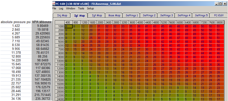
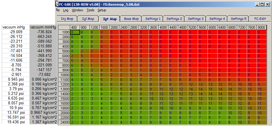
That's a leading from PFC version 5.08 which is what most FD PFC's come with. There may be hundreds, perhaps thousands of FD's running a variation of this map.

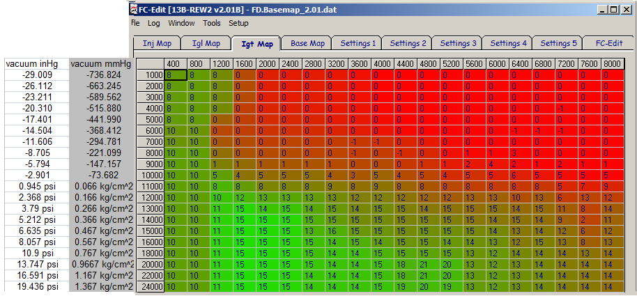
That's from an early version of the PFC, 2.01

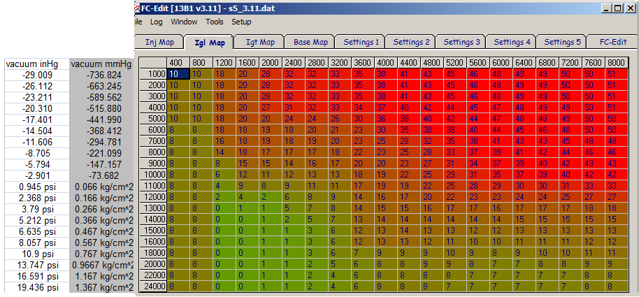
That's from 3.11, the version for the FC series 5 Turbo.
Trailing Split
Most of the trailing/split maps that came with the PFC are kinda ugly but here are two of them.

That's from 5.08, the most common Power FC basemap. I think for most applications it could use more split in the high boost areas.

That's from 2.01. Overall it's a safer split map than the other base maps but it does have a weird spot on the 7600rpm column. The 3.11 (S5 T2) split map is not even worth posting.
Hope that's helpful for you guys who are wondering how your maps compare to what people are running on other systems.
Leading
That's a leading from PFC version 5.08 which is what most FD PFC's come with. There may be hundreds, perhaps thousands of FD's running a variation of this map.
That's from an early version of the PFC, 2.01
That's from 3.11, the version for the FC series 5 Turbo.
Trailing Split
Most of the trailing/split maps that came with the PFC are kinda ugly but here are two of them.
That's from 5.08, the most common Power FC basemap. I think for most applications it could use more split in the high boost areas.
That's from 2.01. Overall it's a safer split map than the other base maps but it does have a weird spot on the 7600rpm column. The 3.11 (S5 T2) split map is not even worth posting.
Hope that's helpful for you guys who are wondering how your maps compare to what people are running on other systems.
talking head
Joined: Apr 2008
Posts: 2,775
Likes: 15
From: Perth, WA, OZ
thanks
would a little easier for most to see if you put the scale in gauge and those vacuums into inch Hg or - psi
( in Hg is almost 2 x the vacuum psi )
if i get this right then 14.5 psi / 101.3 Kpa ( absolute ) is the plot for 0 psi ( gauge ) boost?
also,, are the timing numbers represented as real crank degrees,, or as adding to a -5 datum mark?
Leading
5.08 leading:
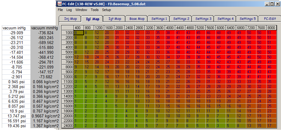
2.01 leading:
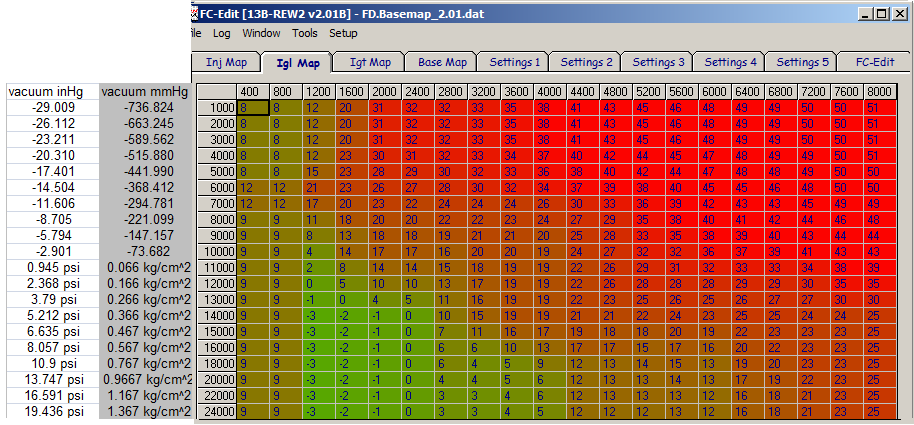
3.11 (s5 T2) leading:
Trailing Split
5.08 split (I don't like this one much)
2.01 split
3.11 split is not worth posting. here is a conversion chart for units
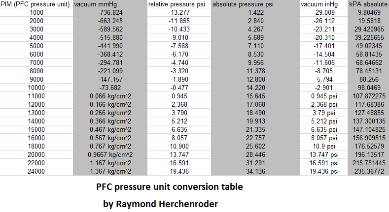
0psi is actually 10335 Power FC pressure units
talking head
Joined: Apr 2008
Posts: 2,775
Likes: 15
From: Perth, WA, OZ
straight up degrees BTDC. no offset or anything like that. However the PFC is a little weird in the sense that it will add a degree of timing on top of the values in the map at like 4000rpm.
,, its not the only ecu or igniter that grows a degree or two as revs increase due to translation of the reluctor timing signals into TTL square signals for the ecu to process
( if you hook some dizzy igniters in reverse polarity they will retard at revs )
not many are aware of it and it should be compensated for in the map tables
,, and yes i was already aware the PFC was one of them
variable reluctor signal translation
,, its not the only ecu or igniter that grows a degree or two as revs increase due to translation of the reluctor timing signals into TTL square signals for the ecu to process
( if you hook some dizzy igniters in reverse polarity they will retard at revs )
not many are aware of it and it should be compensated for in the map tables
,, and yes i was already aware the PFC was one of them

Thread
Thread Starter
Forum
Replies
Last Post
stickmantijuana
Engine Management Forum
11
Nov 9, 2015 01:15 PM
befarrer
Microtech
3
Aug 22, 2015 05:52 PM