LOG IN
REGISTER
Forums
New Member Section
How to use this Site
Introduce yourself
New Member RX-7 Technical
Website-related Comments, Suggestions and Issues
Vendors Forums
Private Vendor Forums
Vendor Classifieds
Generation Specific
3rd Generation Specific (1993-2002)
2nd Generation Specific (1986-1992)
1st Generation Specific (1979-1985)
Old School and Other Rotary
Tech and Performance
General Rotary Tech Support
Race Car Tech
Single Turbo RX-7's
Rotary Car Performance
V-8 Powered RX-7's
Suspension/Wheels/Tires/Brakes
Engine Management Forum
Interior / Exterior / Audio
Classifieds
The NEW RX7 Marketplace
New/Old Products Review - Non Vendor parts
Regional Forums / Upcoming Events
Rotary Owner Events
NE RX-7 Forum
SE RX-7 Forum
Midwest RX-7 Forum
Mountain RX-7 Forum
South RX-7 Forum
NW RX-7 Forum
West RX-7 Forum
Canadian Forum
European Forum
Australia and New Zealand Forum
Far East Forum
Latin America Forum
General Topics
Racing Kills Lounge
RX-7 Audio/Visual Lounge
Test Area 51
Rotary Archives
Marketplace
Vendor Directory
Become a Vendor
Member Marketplace
Vendor Marketplace
New Posts
Tools
Car Payment Calculator
Tire Rim Calculator
Vin Decoder
Recalls
Technical Service Bulletins (TSBs)
Members List
Live Feed
Gallery
View Dark Mode
Please register or login to enable Dark Mode.
Log In
Register
Threads
Google
Threads
Posts
Advanced
Dark Mode
Please register or login to enable Dark Mode.
Log In
Forgot your Password?
By logging into your account, you agree to our
Terms of Use
and
Privacy Policy
, and to the use of cookies as described therein.
or
Login with Google
Login with Facebook
Recent
Commented
Albums
My Pictures
Gen2n3's Photos
View Profile
Sort:
Most Recent
Most Recent
Most Comments
Albums
Photos
IC5 P/N:
0
2017/03/16 12:42:40
Gen2n3
IC1 P/N*: (made by Motorola) 74HC14A 343BW
0
2017/03/16 12:42:38
Gen2n3
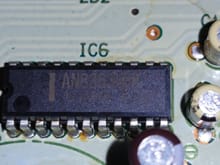
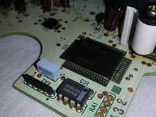
IC6 P/N: AN8363UBK Japan 41.2
0
2017/03/16 12:42:36
Gen2n3
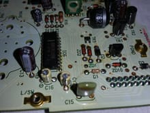
Another general shot of the board with IC6.
0
2017/03/16 12:42:35
Gen2n3
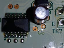
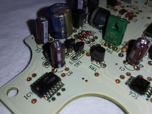
IC6 and the HUGE Zener diode, ZD6.
0
2017/03/16 12:42:33
Gen2n3
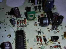
IC3 & IC5 on display.
0
2017/03/16 12:42:31
Gen2n3
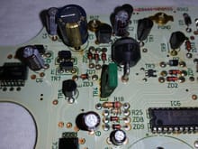
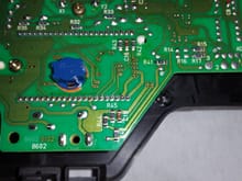
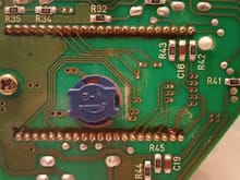
General view of circuit board with IC1. Note that C3 was replaced, aka the blue Panasonic capacitor.
0
2017/03/16 12:42:30
Gen2n3
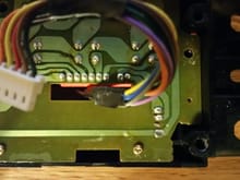
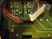
General view of circuit board with speedometer removed.
0
2017/03/16 12:42:28
Gen2n3
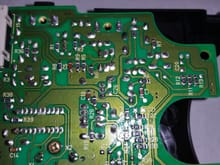
Top 1/3 of the circuit board backside.
0
2017/03/16 12:42:27
Gen2n3
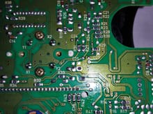
Middle 1/3 of the circuit board backside.
0
2017/03/16 12:42:25
Gen2n3
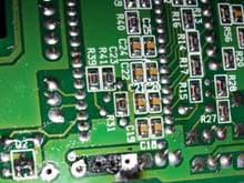
Lower 1/3 of the circuit board backside. Note the surface mounted components.
0
2017/03/16 12:42:23
Gen2n3
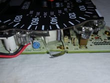
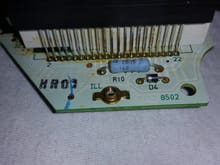
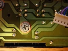
Good view of VR, the adjustment screw to calibrate the speedometer.
0
2017/03/16 12:42:22
Gen2n3
R10 is a 200Ω resistor and diode D4
0
2017/03/16 12:42:17
Gen2n3
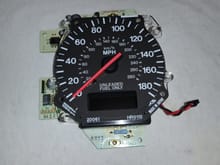
Speedometer Face + Circuit Board
0
2017/03/16 12:40:40
Gen2n3
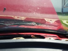
Front windscreen with defrost vent visible.
0
2016/09/07 14:53:22
Gen2n3
Another greyish and flattened solder joint on bottom right.
0
2016/09/05 21:13:21
Gen2n3
Greyish and flattened solder joint on the bottom right.
0
2016/09/05 21:13:20
Gen2n3
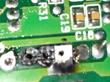
Suspect solder joints. The 2nd from top joint is not supposed to be connected to anything.
0
2016/09/05 21:13:19
Gen2n3
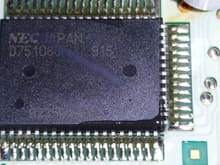
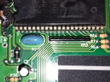
Conformal coating masks the part number on this 42-pin IC
0
2016/08/26 18:33:51
Gen2n3
Top Down
0
2016/08/20 20:47:55
Gen2n3
Top Up
0
2016/08/20 20:47:54
Gen2n3
0
2016/08/20 19:26:41
Gen2n3
Close-up of the missing eyelets. Two of them were removed during desoldering.
0
2016/08/02 07:15:43
Gen2n3
Backside view of the CPU board. Notice the missing eyelets?
0
2016/08/02 07:15:42
Gen2n3
Eyelet damage
0
2016/08/02 07:15:41
Gen2n3
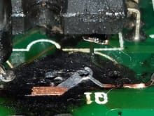
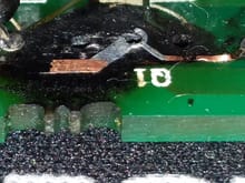
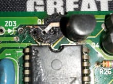
Close-up of burned up solder runs. Note the trace that runs from underneath the IC chip to the right lead of Q1 is nearly gone.
0
2016/08/02 07:15:40
Gen2n3
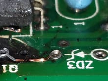
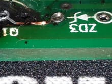
Note the broken solder runs between Q1 and ZD3.
0
2016/08/02 07:15:39
Gen2n3
Lifted eyelets on Q1, backside of the board.
0
2016/08/02 04:55:58
Gen2n3
Broken run to ZD3 and damaged eyelet to ZD3.
0
2016/08/02 04:55:55
Gen2n3
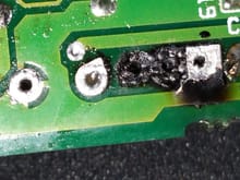
In depth view of solder run damage. Note the missing run at the top center.
0
2016/08/02 04:55:54
Gen2n3
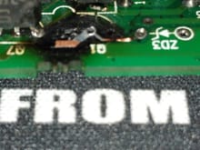
Closer view of solder run damage to Q1 and lifted eyelets.
0
2016/08/02 04:55:53
Gen2n3
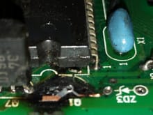
Damage to board, eyelets lifted on Q1, and broken solder runs. A run is lifted under the IC chip that is supposed to extend to the lead (on left) of the transistor Q1.
0
2016/08/02 04:55:10
Gen2n3
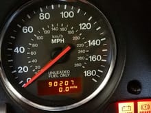
Odometer lives again!
0
2016/04/13 19:21:13
Gen2n3
Here is 22yrs of old flux on the solder cups of the odometer display.
0
2016/04/12 22:38:00
Gen2n3
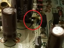
The 1,000uF capacitor leakage within the red circle.
0
2016/04/12 22:37:18
Gen2n3
Back side of odometer display solder joints. This turned out to be 22yr old solder flux.
0
2016/04/12 22:18:37
Gen2n3
1,000uF Capacitor leakage within red circle.
0
2016/04/12 22:17:41
Gen2n3
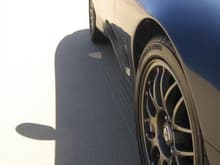
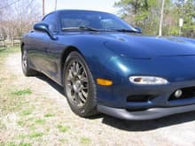
IMG 1368
0
2010/03/19 18:38:52
Gen2n3
IMG 1373
0
2010/03/19 18:38:52
Gen2n3
IMG 1358
0
2010/03/19 18:38:52
Gen2n3
First
Page
5 of 15
Last
Go To
Page
1
2
3
4
5
6
7
...
15
5 of 15
Go To
GO
Go to page
of 15
pages
1
2
3
4
5
6
7
...
15