
How to convert to a internally regulated altarnator?


Step one, spell alternator correctly.
Step two, goto
http://www.nellump.net/peri/epi/firs...orUpgrade.html
Step two, goto
http://www.nellump.net/peri/epi/firs...orUpgrade.html
This is a better explaination by Rubin.
Upgrading '79/'80 alternator to '81+
The reason I replaced my alternator with a newer one was because the
external regulator/relay was fried. I couldn't find a replacement
so I put in a newer internally-regulated alternator ('81 or newer).
This forced me to remove the external regulator and replace it with
just a standard automotive relay in order to properly operate the dashboard
light/meter and the choke heater).
The battery terminal (thick black wire with ring-terminal) is the
same for old/new alternators.
The following diagram is the connector on the back the new alternator
(2 terminal) which is different from the old one (4 terminal). At
this point I'm not going to say which wires in the harness can/should
be reused, it complicates the description. For now, just run two
new wires to make sure it works first.
___TAB___
| |
| --- | <--------- Ig
|__ __|
| |
| | | <--------- Re
|___|
The Ig wire should be your own connection to to a 12V source when the
key is ON ignition.
The Re wire should be connected to the relay below.
The relay should be wired as follows:
YL Y Re
| | |
| | (
N/O / N/C ! ) COIL
| | (
| | )
Ground Ground |
12V ignition source
(N/O is normally open, N/C is normally closed)
The following wires are found on the vehicle side of the connector
when the regulator is disconnected and removed (it's good space to put your
new relay):
YL: Yellow/Light Blue stripe (on the big connector) (goes to dashboard)
Y: Yellow (on it's own connector) (goes to choke relay)
Make your own connection:
Re: Connect to Re terminal at alternator.
Theory: Assume ignition is switched on.
When engine is not running OR alternator is bad, there will be 0V at the
Re terminal causing the relay to energize. The relay will:
- - YL to ground (causing the dahsboard light/meter to activate)
- - Y to open circuit (disabling the choke heater relay)
When the engine is running AND the alternator is good, there will be 12V
at the Re terminal, the relay will not energize. The relay will:
- - YL to open circuit (dashboard will be normal)
- - Y to ground (enabling the choke heater relay)
***
Disclaimer... I'm not responsible for anything that happens by following
these directions. Any connections should be double checked in the Haynes
manual and/or tested with a meter.
Wants Traction!
Joined: Dec 2005
Posts: 292
Likes: 0
From: Regina, SK, Canada
Ok, i need help with this. That txt diagram does not help me at all. this is the relay i got. only one the stores had. sorry for the bad picture of the box but can someone please help me out.
Trending Topics
You dont need that crap. Install the 81-88 alternator. Find a 12V source when the key is on. Connect a wire from this point to the back of alternator as shown in the following picture. There is another way but I need a couple more heine's. My memory is bad without it.
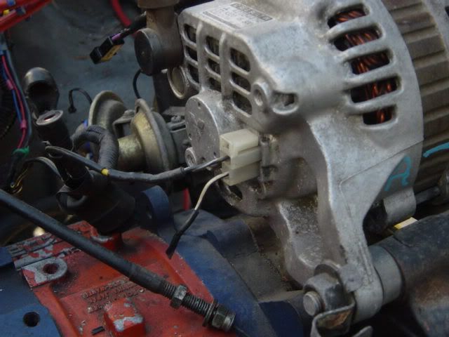
Originally Posted by wackyracer
You dont need that crap. Install the 81-88 alternator. Find a 12V source when the key is on. Connect a wire from this point to the back of alternator as shown in the following picture. There is another way but I need a couple more heine's. My memory is bad without it.
wacky--thats all you have to do to install a 81-88 alt in a SA? what about a 89+? splice the wire into the S5/S6 connector and do it just like above?


wacky--if im not mistaken wont running that one wire straight to the other post make the alt drain the battery if the car is left off for an extended amount of time. i think that makes it pull power constantly. i could easily be wrong though.
Thats 100% correct but some says it has minimal voltage loss. If you're worried about power loss, I highly recommend using a fog lights relay to open the circuit when parked. Just connect 85 or 86 terminal to an ignition wire to trigger the relay.

Thread
Thread Starter
Forum
Replies
Last Post
killerrx710
Adaptronic Engine Mgmt - AUS
5
Sep 28, 2015 09:13 AM
killerrx710
2nd Generation Specific (1986-1992)
1
Sep 24, 2015 10:57 PM
t-von
3rd Generation Specific (1993-2002)
9
Sep 10, 2015 01:56 PM
14105, 1985, alt, altarnator, alternator, basic, cable, internally, principle, regulated, rx7, wire, wiring