13b Supercharger Manifold
 12-17-10, 09:52 PM
#1
Senior Member
Thread Starter
iTrader: (1)

Join Date: Dec 2008
Location: Vancouver, BC
Posts: 250
Likes: 0
Received 0 Likes
on
0 Posts
13b Supercharger Manifold
I've started in on one of my personal projects. I'm putting an Eaton M90 onto my track car (86 gxl). Since there is so little information on supercharged rotaries I figured I'd share.
Bellow are the cad renderings. I've machined about 75% of the parts for the manifold so far. Originally I was designing a set up to clear the OEM hood, but in an effort to get this finished quickly I switched to a set up that will bolt to a S4 manifold. This puts the blower above the hood line, but was easier to do and for a track car I don't mind cutting a hole in the hood.


Bellow are the cad renderings. I've machined about 75% of the parts for the manifold so far. Originally I was designing a set up to clear the OEM hood, but in an effort to get this finished quickly I switched to a set up that will bolt to a S4 manifold. This puts the blower above the hood line, but was easier to do and for a track car I don't mind cutting a hole in the hood.
 12-19-10, 11:59 PM
#3
Senior Member
Thread Starter
iTrader: (1)
Join Date: Dec 2008
Location: Vancouver, BC
Posts: 250
Likes: 0
Received 0 Likes
on
0 Posts
Thanks. I ran into problems trying to weld the runners in, so I'm recutting some of the parts. I'll post some more pictures as progress is made.
12-20-10, 12:17 AM
#4
HKS obsessed
iTrader: (7)
Join Date: Mar 2008
Location: OP, KS
Posts: 1,529
Likes: 0
Received 0 Likes
on
0 Posts
That's sick looks like a great manifold and the runners should match up well!
What else are the plans for the motor? Just stock with the supercharger on it? Or actual built motor?
What else are the plans for the motor? Just stock with the supercharger on it? Or actual built motor?
12-20-10, 12:26 AM
#5
Senior Member
Thread Starter
iTrader: (1)
Join Date: Dec 2008
Location: Vancouver, BC
Posts: 250
Likes: 0
Received 0 Likes
on
0 Posts
For this season I'll most likely just be running the stock motor, unless I somehow find some time to build a new one for it. This years focus is on getting the chassis set up and track ready as well as building the supercharger set up.
Things always take longer then I plan them to, so this year my focus is just on getting things running and from there I will slowly upgrade and improve the set up. Right now the biggest problem I'm having is joining the engine side flange/runners/plenum floor. Everything is too close together for my welding skills.
Right now the plan is to use a 0.003 press fit and sleeve retainer, but I am also going to talk to someone who is a better welder then me, to see if maybe they can do the welding.
 12-20-10, 05:11 AM
#7
Senior Member
Thread Starter
iTrader: (1)
Join Date: Dec 2008
Location: Vancouver, BC
Posts: 250
Likes: 0
Received 0 Likes
on
0 Posts
Thats a future plan. The laminova cores are not cheap though, and before I buy them, I want to know for sure that I can not only build the manifold but all the other parts of the system. The plenum was designed to fit two of the short laminova cores though, and there will be enough clearance front and rear for the fittings.
Trending Topics
12-20-10, 06:48 AM
#8
Rotary Enthusiast
exactly.
dont know if you have seen this kit.
http://www.scienceofspeed.com/produc...a_Intercooler/


http://www.scienceofspeed.com/produc...sembly_800.jpg
I want to go something like this but then have your plenum adapter under it to convert it back to the 13b LIM
dont know if you have seen this kit.
http://www.scienceofspeed.com/produc...a_Intercooler/
http://www.scienceofspeed.com/produc...sembly_800.jpg
I want to go something like this but then have your plenum adapter under it to convert it back to the 13b LIM
12-20-10, 03:02 PM
#9
Senior Member
Thread Starter
iTrader: (1)
Join Date: Dec 2008
Location: Vancouver, BC
Posts: 250
Likes: 0
Received 0 Likes
on
0 Posts
I have seen that kit before. It's very nice looking and appears well made, as do many of their parts.
The only thing that I wonder about is what sort of pressure drop they are seeing across the cores. They mention a 1.2 psi drop before and after, but thats manifold pressure not pressure drop through the cores. The laminova cores are supposed to have very little pressure drop across them which in theory means any additional pressure drop is due to other restrictions.
The only thing that I wonder about is what sort of pressure drop they are seeing across the cores. They mention a 1.2 psi drop before and after, but thats manifold pressure not pressure drop through the cores. The laminova cores are supposed to have very little pressure drop across them which in theory means any additional pressure drop is due to other restrictions.


 12-21-10, 01:14 AM
#12
Senior Member
Thread Starter
iTrader: (1)
Join Date: Dec 2008
Location: Vancouver, BC
Posts: 250
Likes: 0
Received 0 Likes
on
0 Posts
Oh and I should mention, the machining isn't the best. I don't have the time right now for custom fixtures and subplates, so basically I'm just doing what will work to get me parts for prototyping.
12-22-10, 02:36 AM
#16
Senior Member
Thread Starter
iTrader: (1)
Join Date: Dec 2008
Location: Vancouver, BC
Posts: 250
Likes: 0
Received 0 Likes
on
0 Posts
As far as power goes I'm not expecting to crack 300whp. I'm building the car as a bracket racer, so I'm mostly focused on getting out of the hole quickly and running consistent.
Eaton recommends 16,000 rpm max, but you can rebuild them with better bearings and rumor has it you can wind them out to closer to 24,000 rpm. Only two things happen when you over rev them though (not counting efficiency drops) . The bearing wear faster and the rotors can rub the housing. This isn't ideal and the blower may be wrecked, but the engine should survive.
Eaton recommends 16,000 rpm max, but you can rebuild them with better bearings and rumor has it you can wind them out to closer to 24,000 rpm. Only two things happen when you over rev them though (not counting efficiency drops) . The bearing wear faster and the rotors can rub the housing. This isn't ideal and the blower may be wrecked, but the engine should survive.
12-22-10, 02:54 AM
#17
Senior Member
Thread Starter
iTrader: (1)
Join Date: Dec 2008
Location: Vancouver, BC
Posts: 250
Likes: 0
Received 0 Likes
on
0 Posts
Below is a simulation of the power output of an M90 on a 13B. Using the parameters of this model the blower is withing the OEM safe limit. This simulation assumed an intercooler efficiency of 75%. This is just a simulation and obviously not definitive data, but it should be accurate +/- 10% and still leave a fair bit of room in the system to squeeze more power out of it.

12-27-10, 09:07 PM
#18
^ Unless that supercharger is doing something crazy down low you may wanna re-check that calibration because that simulation is nuts if it thinks a 13b rotary can make over 150lbs at idle. However if it can get close, you would have completley made a new case for rotary low end torque that even the twins can't match.
Nice manifold by the way.
Nice manifold by the way.
12-29-10, 12:59 AM
#19
Senior Member
Thread Starter
iTrader: (1)
Join Date: Dec 2008
Location: Vancouver, BC
Posts: 250
Likes: 0
Received 0 Likes
on
0 Posts
The great thing about blowers is that they are the most efficient where the engine is the least efficient. On the rotary it's down low.
This is a dyno of a s4 running a less efficient blower at 5psi. If you look you'll see it's making about 90 whp at 1500. So 150 flywheel off idle isn't that unrealistic. I've also seen some dynos of the renisis motor with a blower and they are making over 150 off idle, which is a good 40% increase.
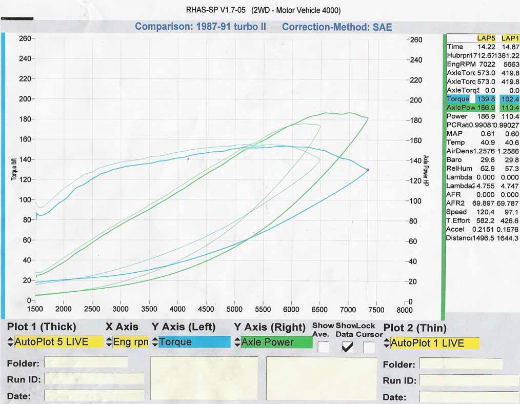
This is a dyno of a s4 running a less efficient blower at 5psi. If you look you'll see it's making about 90 whp at 1500. So 150 flywheel off idle isn't that unrealistic. I've also seen some dynos of the renisis motor with a blower and they are making over 150 off idle, which is a good 40% increase.
01-13-11, 03:00 AM
#22
Senior Member
Thread Starter
iTrader: (1)
Join Date: Dec 2008
Location: Vancouver, BC
Posts: 250
Likes: 0
Received 0 Likes
on
0 Posts
No new pics, but figured I'd give a quick update for those following.
I stuck my head into a shop that I make parts for and talked to their welder. He's confident he can weld it up once I make a few small changes. I'm hoping to drop it off in a few days and be able to finalize the upper port placement. In the mean time I'm going to start designing the new pulleys, although I may hold off on making them until my little cnc lathe is ready.
I stuck my head into a shop that I make parts for and talked to their welder. He's confident he can weld it up once I make a few small changes. I'm hoping to drop it off in a few days and be able to finalize the upper port placement. In the mean time I'm going to start designing the new pulleys, although I may hold off on making them until my little cnc lathe is ready.
01-20-11, 02:13 AM
#24
Senior Member
Thread Starter
iTrader: (1)
Join Date: Dec 2008
Location: Vancouver, BC
Posts: 250
Likes: 0
Received 0 Likes
on
0 Posts
Yes I did, I wanted the runners in the manifold to match the lower manifold as close as possible. I designed everything myself and machined the parts in house. I'm sending it out for welding though ... it's to tight of an area for my limited welding skills.