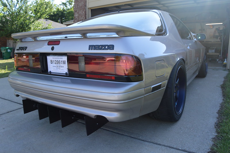
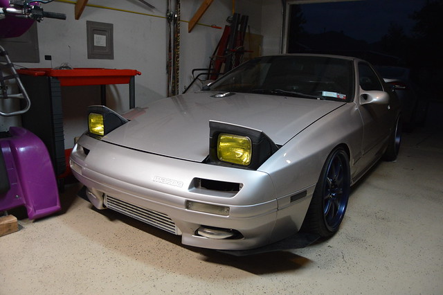
A classy FC3S drift build


Thread Starter
Full Member
Joined: Nov 2013
Posts: 94
Likes: 2
From: NY
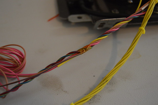
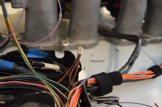
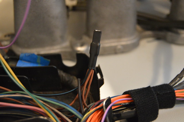
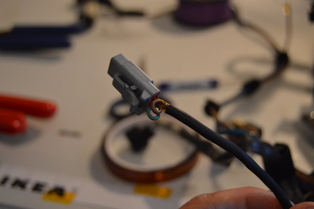
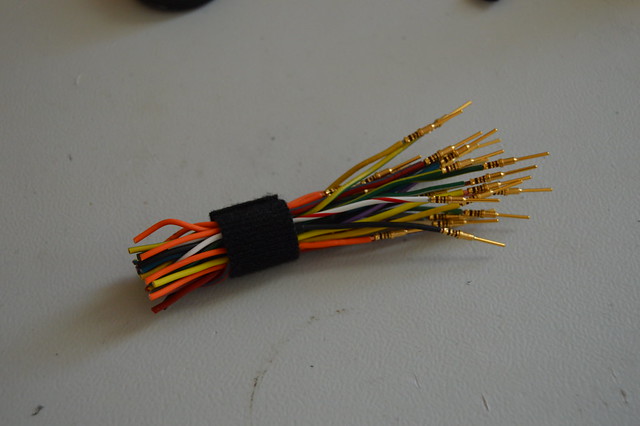
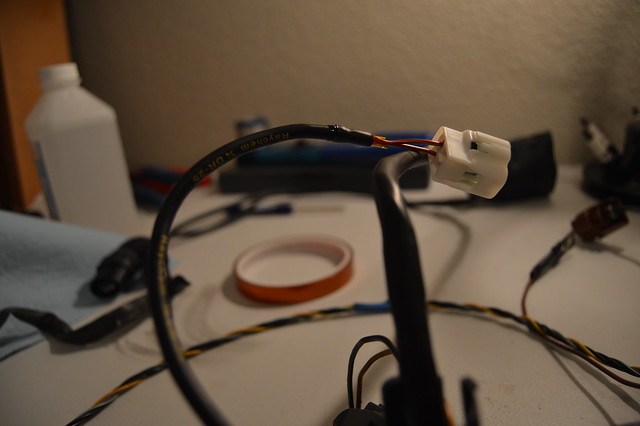
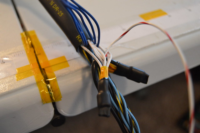
I was also itching to use my DMC crimper so i terminated this 6 pin DTM which will be used for my CAN, shielding ground, tach output, 2 step switch, and 12V switched power for the AEM UEGO.

Now i have to order my heatshrink and boot before terminating the bulk head. I am also ordering my ING1A ignition system before starting on the engine side. Still need to route and terminate new wires for my EOT, IAT, EOP, FRP, ECS, and MAP sensors. Also ran into an issue with the swirl pot setup the shop made me. There is just not enough room to plug the ECT connector in so after talking to the shop they want to pot the ECT sensor which i thought was a great idea. Basically they will remove the pins from the connector, plug them in on the sensor, then fill the sensor socket with epoxy. A DTM connector will then be added a few inches further down the circuit. Something i can do but will let them handle it since its kinda their fault. They need to weld on an IAT bung, -10 bung, and second UEGO bung anyways for me. Waiting on the correct fuse box to arrive and then i can start on terminating that.
Now i have to order my heatshrink and boot before terminating the bulk head. I am also ordering my ING1A ignition system before starting on the engine side. Still need to route and terminate new wires for my EOT, IAT, EOP, FRP, ECS, and MAP sensors. Also ran into an issue with the swirl pot setup the shop made me. There is just not enough room to plug the ECT connector in so after talking to the shop they want to pot the ECT sensor which i thought was a great idea. Basically they will remove the pins from the connector, plug them in on the sensor, then fill the sensor socket with epoxy. A DTM connector will then be added a few inches further down the circuit. Something i can do but will let them handle it since its kinda their fault. They need to weld on an IAT bung, -10 bung, and second UEGO bung anyways for me. Waiting on the correct fuse box to arrive and then i can start on terminating that.
Thread Starter
Full Member
Joined: Nov 2013
Posts: 94
Likes: 2
From: NY
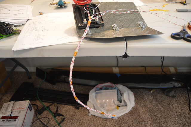
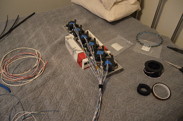
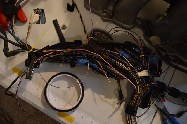
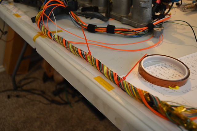
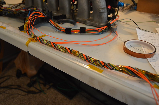
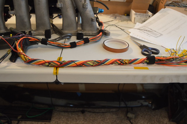
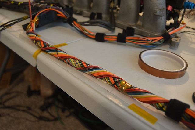
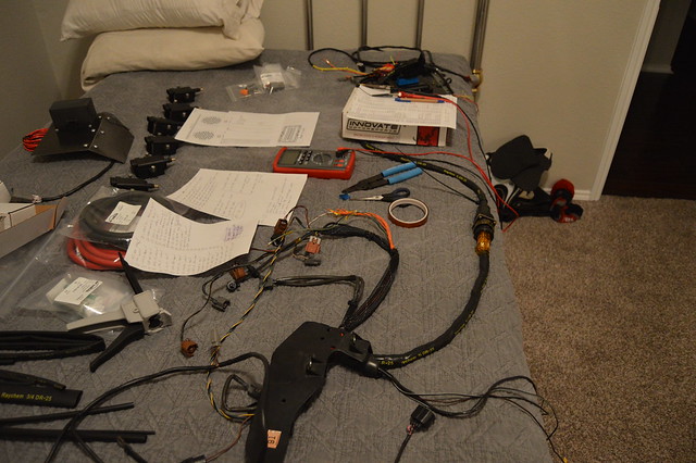
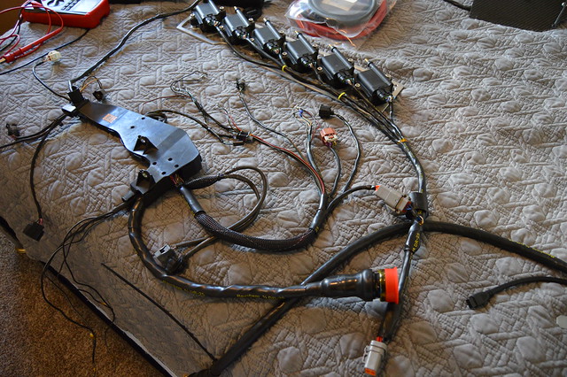
Back at it! Finished up the harness and got some other things checked off the never ending list. We will start off with a big order from prowire with everything else i need to wrap up the chassis harness.
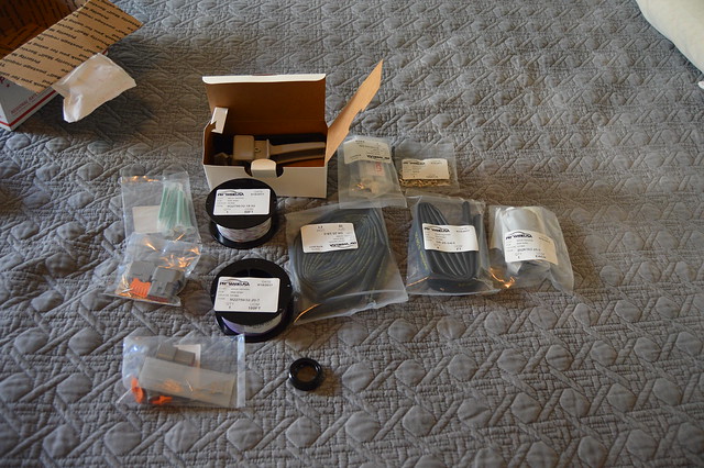
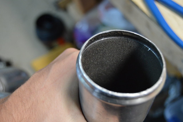
Most importantly this back shell, the heat shrink, and heat shrink boot.
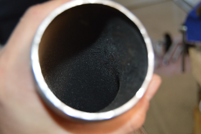
Started off sliding on the heatshrink and shrinking 90%.
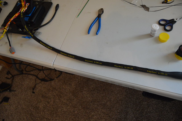
Then brought my vice inside and got ready to party
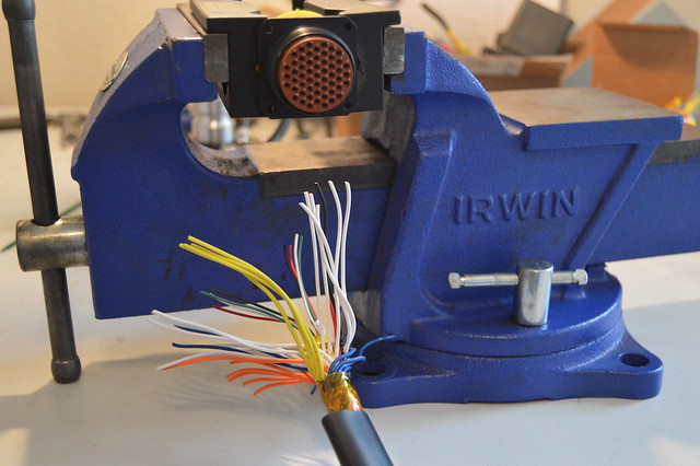
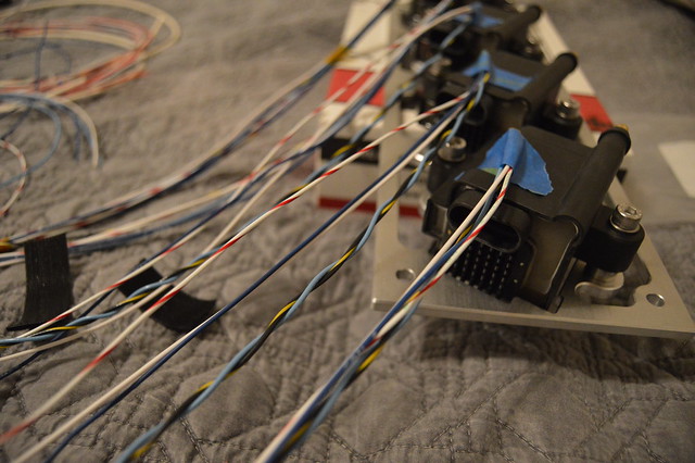
So right as i am getting ready to crimp the first pin i realize that the pins for the milspec connector will not slide into my crimp tool however the pins from the Deutsch connectors slide in with some resistance. Now this is what i get for buying tools this critical used, however i ponied up, found a drill bit barely larger, coated it in grease and drilled (more like honed) the bore on the crimp tool. after this all the pins slid in like butter and i got back to work.
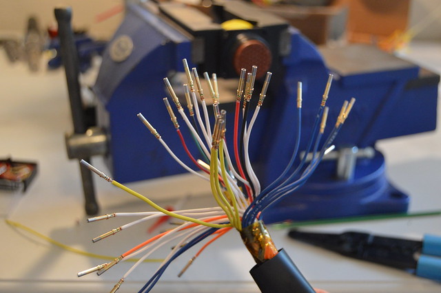
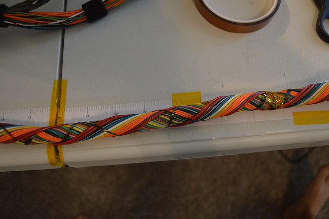
Was really in the zone so forgot to take pictures but started with this. I am using 3mm knitting needles which i got at Michaels for the service loops.
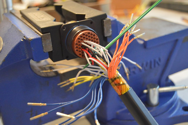
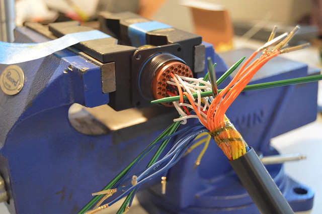
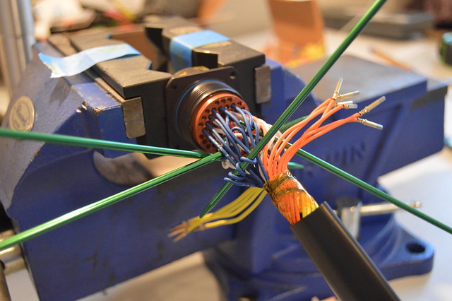
And ended up here. I will say that this is an area i wish looked better but it functions so thats all that matters. Staggering the service loops to look pretty was very hard mainly due to me not leaving enough wire free length. Biggest take away for me here is to leave much more wire length next time.
Most importantly this back shell, the heat shrink, and heat shrink boot.
Started off sliding on the heatshrink and shrinking 90%.
Then brought my vice inside and got ready to party
So right as i am getting ready to crimp the first pin i realize that the pins for the milspec connector will not slide into my crimp tool however the pins from the Deutsch connectors slide in with some resistance. Now this is what i get for buying tools this critical used, however i ponied up, found a drill bit barely larger, coated it in grease and drilled (more like honed) the bore on the crimp tool. after this all the pins slid in like butter and i got back to work.
Was really in the zone so forgot to take pictures but started with this. I am using 3mm knitting needles which i got at Michaels for the service loops.
And ended up here. I will say that this is an area i wish looked better but it functions so thats all that matters. Staggering the service loops to look pretty was very hard mainly due to me not leaving enough wire free length. Biggest take away for me here is to leave much more wire length next time.
Thread Starter
Full Member
Joined: Nov 2013
Posts: 94
Likes: 2
From: NY
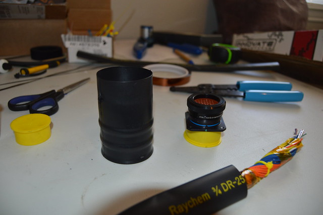
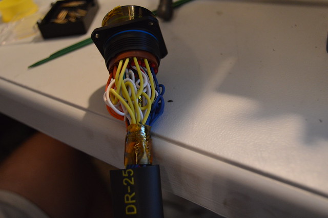
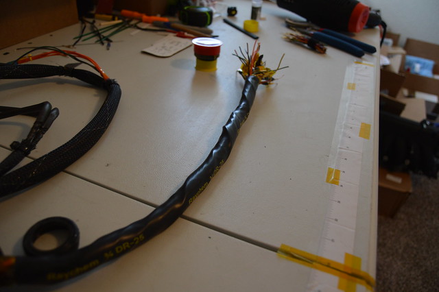
wrapped in kapton tape ready to be booted
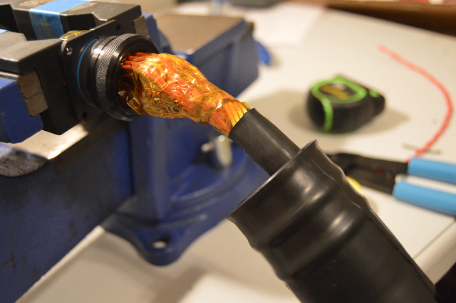
This was face paced, throw a bead of epoxy on the backshell, heat boot evenly,wipe excess, then throw a bead on the harness side, then heat evenly until we got this
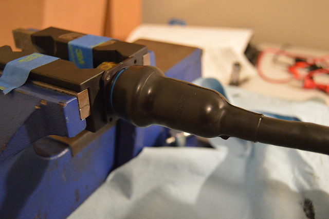
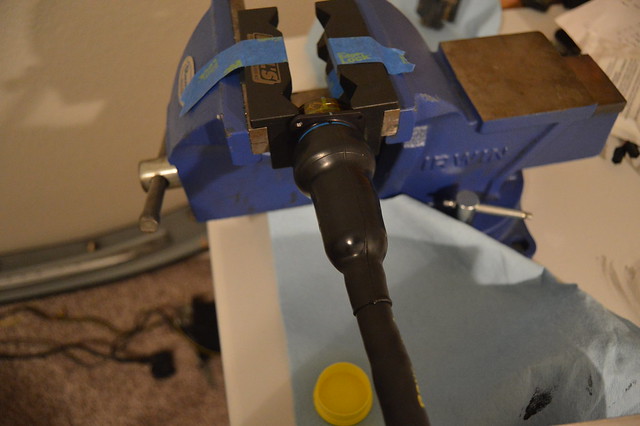
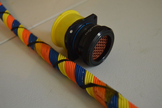
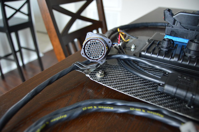
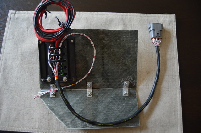
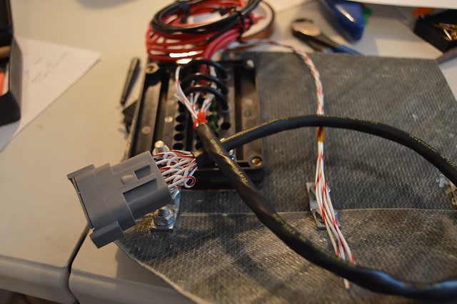
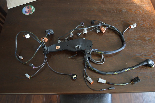
Finished product. At some point i slid on the raychem for my power loom then added a 12 point Deutsch which will be mated to my fuse box.
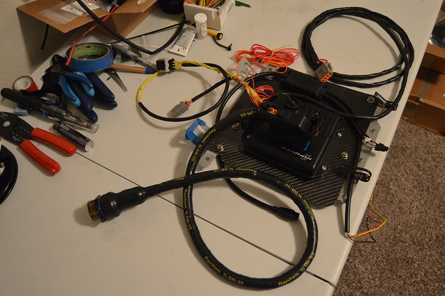
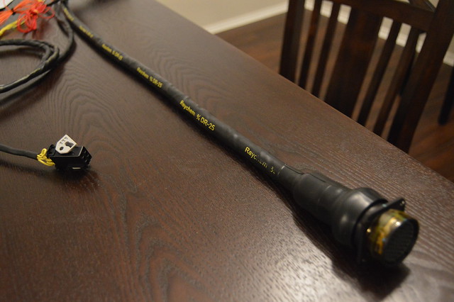
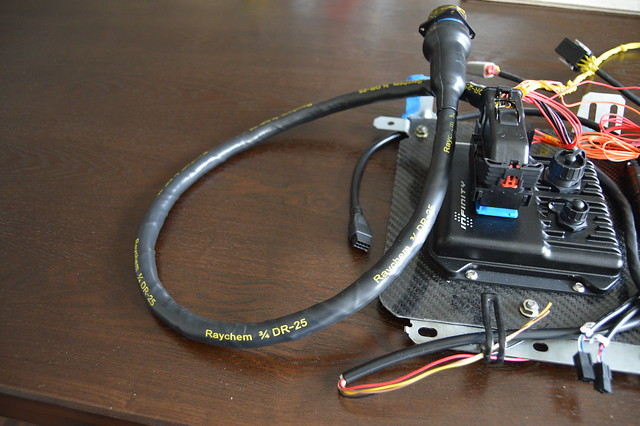
This was a 55 pin and i only used 38 total pins with 2 shielded circuits dead ended at the connector. I chose to pin it like this due to the injector circuits being too short for other locations. Lesson definitely learned.
This was face paced, throw a bead of epoxy on the backshell, heat boot evenly,wipe excess, then throw a bead on the harness side, then heat evenly until we got this
Finished product. At some point i slid on the raychem for my power loom then added a 12 point Deutsch which will be mated to my fuse box.
This was a 55 pin and i only used 38 total pins with 2 shielded circuits dead ended at the connector. I chose to pin it like this due to the injector circuits being too short for other locations. Lesson definitely learned.
Thread Starter
Full Member
Joined: Nov 2013
Posts: 94
Likes: 2
From: NY
Also swung by my fab shop earlier in the week and got the IAT, breather bung, and second O2 bung welded on while i waited.
ordered my IGN1A kit from induction performance. Very pleased with this kit as it included everything down to connectors and pins.
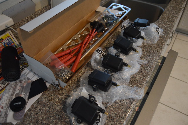
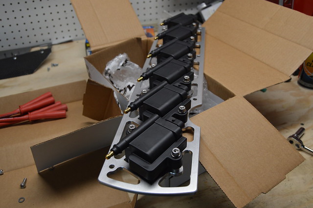
Now i was pretty happy with being able to run the stock hood to fit the engine since it was apparently unheard of, but after much consideration i decided to go with this kit so that i will never have to upgrade again. The other option was OEM USDM coils but the used price of those was about the same as this proven kit. I saw the majority of crazy supras at TX2K running this same setup. I will be running a URAS style vent to clear the front two coils which should help with underhood temps drastically.
Next up is installing the engine side harness to verify wire lengths for my additional circuits/sensors and then splice in my 5V and 12V along with pinning out the connector. I will also run an ignition sub harness with new tefzel wiring, raychem, etc. My current plan is to get the car running on the stripped and modified OEM harness (verified through load testing to be functional) and then build a mil spec style harness in the near future using new OEM connectors and tefzel wiring. This will be easy due to the detailed documentation i have been making along the way. I need to order a driveshaft, power steering lines/ reservoir, and plug a few coolant ports before we can add fluids, load a base tune, and fire her up!!!!!!
ordered my IGN1A kit from induction performance. Very pleased with this kit as it included everything down to connectors and pins.
Now i was pretty happy with being able to run the stock hood to fit the engine since it was apparently unheard of, but after much consideration i decided to go with this kit so that i will never have to upgrade again. The other option was OEM USDM coils but the used price of those was about the same as this proven kit. I saw the majority of crazy supras at TX2K running this same setup. I will be running a URAS style vent to clear the front two coils which should help with underhood temps drastically.
Next up is installing the engine side harness to verify wire lengths for my additional circuits/sensors and then splice in my 5V and 12V along with pinning out the connector. I will also run an ignition sub harness with new tefzel wiring, raychem, etc. My current plan is to get the car running on the stripped and modified OEM harness (verified through load testing to be functional) and then build a mil spec style harness in the near future using new OEM connectors and tefzel wiring. This will be easy due to the detailed documentation i have been making along the way. I need to order a driveshaft, power steering lines/ reservoir, and plug a few coolant ports before we can add fluids, load a base tune, and fire her up!!!!!!
Thread Starter
Full Member
Joined: Nov 2013
Posts: 94
Likes: 2
From: NY
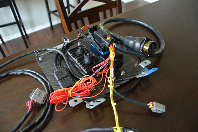
Pulled the dash this morning and installed the harness. Very happy with how it fits. The extra bundled wire is for the boost control solenoid, and ignition switch 12V. I will go through the oem ECU harness sitting on the bottom and steal some switched 12V for use in this case.
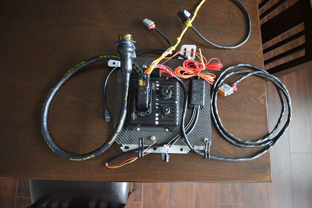
With that done i terminated my fuse box and verified the wire lengths. I have terminated this with 4 total relays (2 extra) and wired the fuses on the outside so i can add additional circuits for whatever. This is being used for the ECU power circuits, cooling fan relay, and fuel pump relay which are both controlled by the infinity. Extra wire on top is for the cooling fan and fuel pump output. The extra 18 gauge circuits are the ECU grounds which will be ran to a bus bar then battery ground.

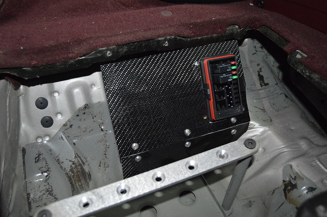
With that done i terminated my fuse box and verified the wire lengths. I have terminated this with 4 total relays (2 extra) and wired the fuses on the outside so i can add additional circuits for whatever. This is being used for the ECU power circuits, cooling fan relay, and fuel pump relay which are both controlled by the infinity. Extra wire on top is for the cooling fan and fuel pump output. The extra 18 gauge circuits are the ECU grounds which will be ran to a bus bar then battery ground.
Thread Starter
Full Member
Joined: Nov 2013
Posts: 94
Likes: 2
From: NY
More wiring updates
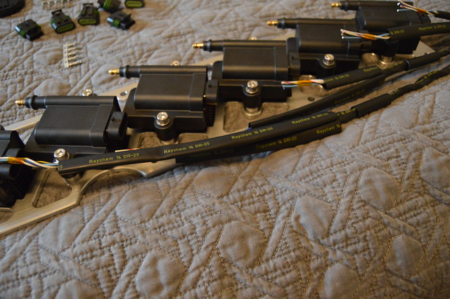
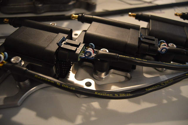
Due to supplies on hand and waiting on a few OEM toyota connectors i started on the ignition harness. These coilpacks are 5 wire, one 12V HV power, one HV 12V ground which i used 16ga for, then one signal ground (22ga), a cylinder head ground (18ga), and finally the trigger (22ga).
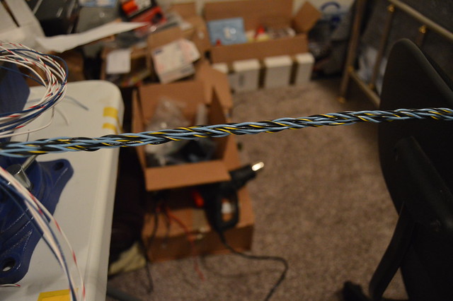
Twisted the high voltage circuits to reduce EMI
6- 16ga pair circuit core
one layer of 18ga
final layer of signal ground and trigger circuits. Splices will be done at the connector end

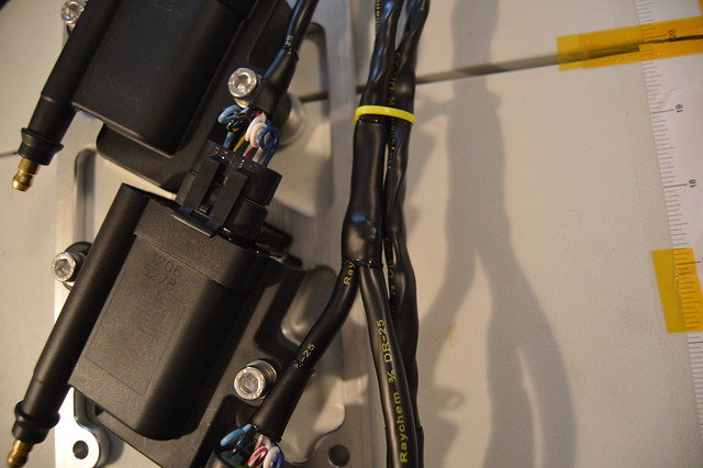
then worked on breakouts and individual branches
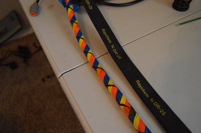
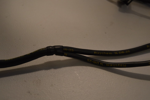
and DR25 treatment with raychem SCL (adhesive lines) used for the transitions and break outs.
Due to supplies on hand and waiting on a few OEM toyota connectors i started on the ignition harness. These coilpacks are 5 wire, one 12V HV power, one HV 12V ground which i used 16ga for, then one signal ground (22ga), a cylinder head ground (18ga), and finally the trigger (22ga).
Twisted the high voltage circuits to reduce EMI
6- 16ga pair circuit core
one layer of 18ga
final layer of signal ground and trigger circuits. Splices will be done at the connector end
then worked on breakouts and individual branches
and DR25 treatment with raychem SCL (adhesive lines) used for the transitions and break outs.
Thread Starter
Full Member
Joined: Nov 2013
Posts: 94
Likes: 2
From: NY
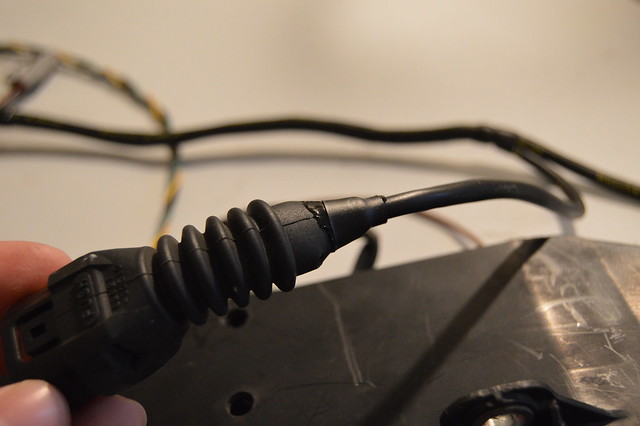
these utilize pull to seat connectors/pins= pain in the ***
waiting on some more heatshrink and a boot for the main break out but it will be routed behind the FPR and finished off with an 8 pin DTM for the signal ground/ triggers and then a 4 pin DTP for the 12V and ground circuits.

Engine side harness is mainly completed but i totally fucked up the length and decided to repin the entire connector. If you remember the chassis side i ran some circuits too short and this ended up being a pain in the *** causing me to skip positions in the connector. This time i left too much slack and didnt like how the harness was routed afterwords. Already pulled the pins out of the bulkhead and chopped it too the right length. Should have that repinned and booted by this weekend and can start on running battery cable.
Anways, before we got to the bulkhead i cleaned up all the remaining circuits/ connectors not being used and ran new circuits for my added sensors.
Before-
After-
I was investigating the OEM splices when i found they were filled with some sort of dielectric grease
Ended up redoing all the splices except for the injector one as i am waiting on a larger size crimp splice. These are the parallel splices crimped with the indent crimp on my metri pack crimp tool.
I did do a few tests of various wire size and arrangement prior to starting. These are finished off with raychem SCL which is adhesive lined.
waiting on some more heatshrink and a boot for the main break out but it will be routed behind the FPR and finished off with an 8 pin DTM for the signal ground/ triggers and then a 4 pin DTP for the 12V and ground circuits.
Engine side harness is mainly completed but i totally fucked up the length and decided to repin the entire connector. If you remember the chassis side i ran some circuits too short and this ended up being a pain in the *** causing me to skip positions in the connector. This time i left too much slack and didnt like how the harness was routed afterwords. Already pulled the pins out of the bulkhead and chopped it too the right length. Should have that repinned and booted by this weekend and can start on running battery cable.
Anways, before we got to the bulkhead i cleaned up all the remaining circuits/ connectors not being used and ran new circuits for my added sensors.
Before-
After-
I was investigating the OEM splices when i found they were filled with some sort of dielectric grease
Ended up redoing all the splices except for the injector one as i am waiting on a larger size crimp splice. These are the parallel splices crimped with the indent crimp on my metri pack crimp tool.
I did do a few tests of various wire size and arrangement prior to starting. These are finished off with raychem SCL which is adhesive lined.
Thread Starter
Full Member
Joined: Nov 2013
Posts: 94
Likes: 2
From: NY
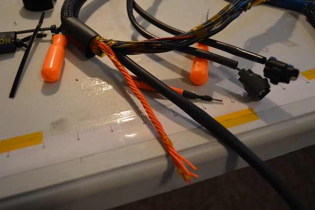
And some shots of additional connectors i added. I did reuse some of the OEM wiring here after testing it out via a load test. The copper was also a bright color on everything i reused. Did find some greenish strands in some cases which i threw out.
This picture shows off the size of the tefzel (milspec) wiring nicely. The purple circuit (tefzel) is 20 gauge and the black/ yellow-green circuits are 22 gauge. The tefzel wiring is much smaller in total diameter due to the thinner outer insulation. This insulation is also much more difficult to strip and overall much tougher.
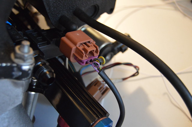
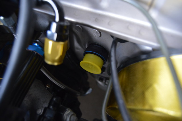
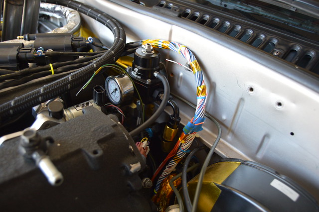
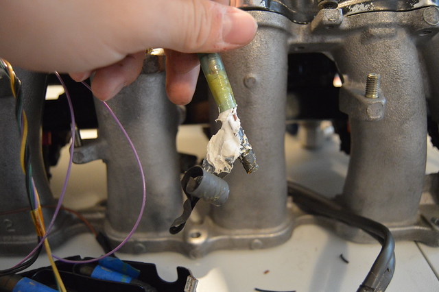
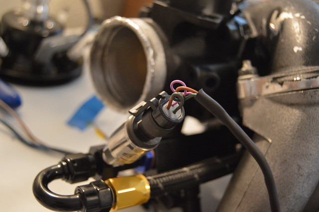
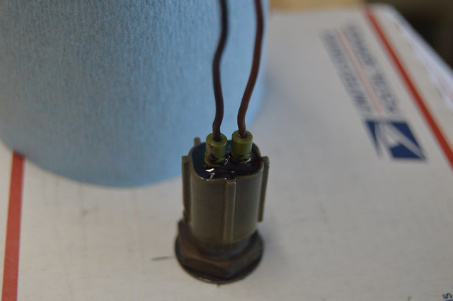
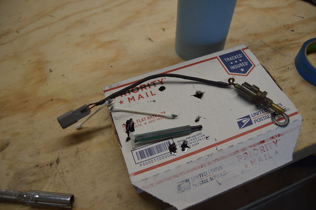
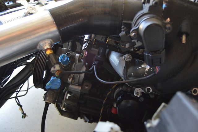
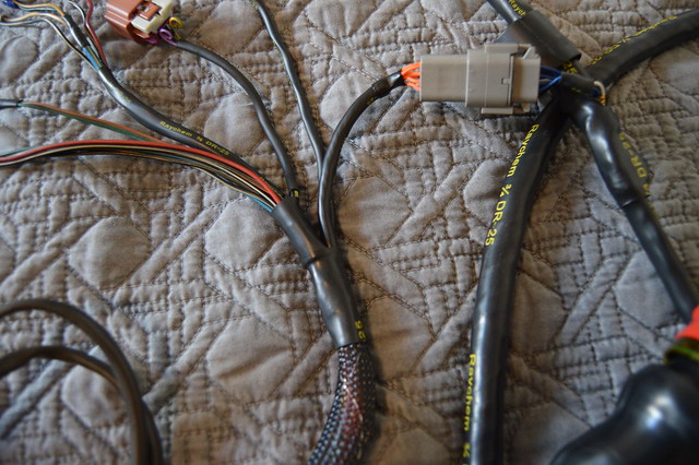
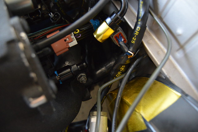
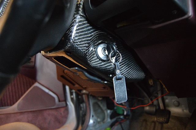
Also potted the coolant temp sensor and wrapped it up with a DTM. It now clears the swirl pot.
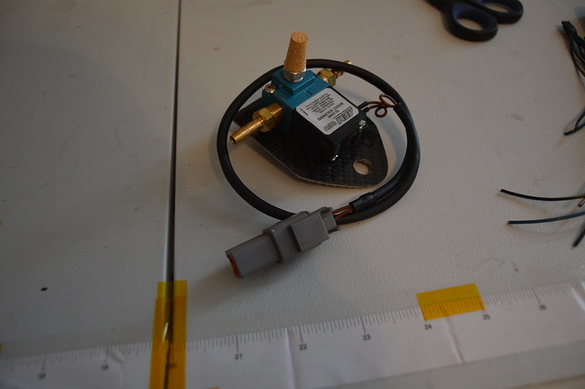
BCS got the same treatment
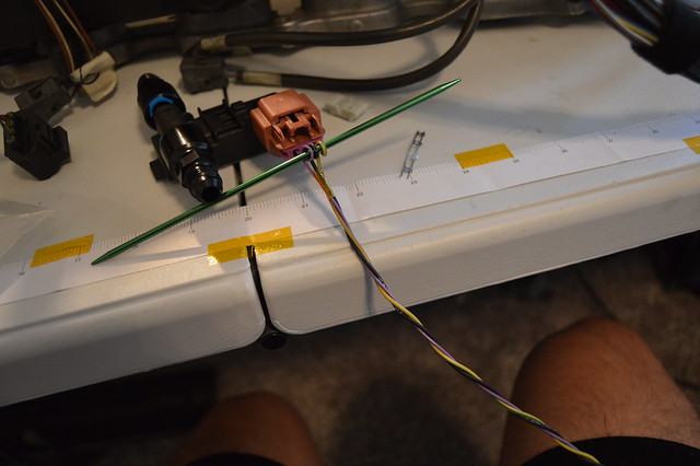
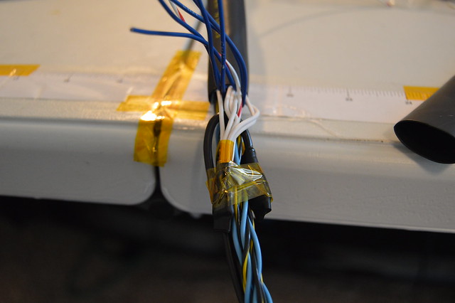
IAT, fuel rail pressure, TPS, and VVTI breakout.
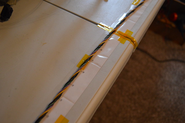
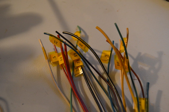
Before cutting off the OEM connectors i numbered all the circuits which made pinning the bulkhead a breeze.
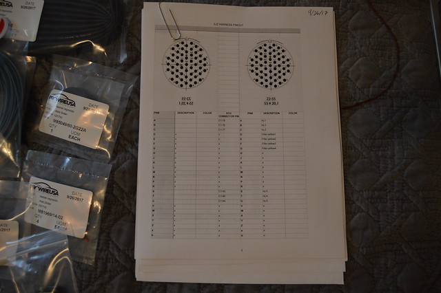
spreadsheet i made using pinouts
This picture shows off the size of the tefzel (milspec) wiring nicely. The purple circuit (tefzel) is 20 gauge and the black/ yellow-green circuits are 22 gauge. The tefzel wiring is much smaller in total diameter due to the thinner outer insulation. This insulation is also much more difficult to strip and overall much tougher.
Also potted the coolant temp sensor and wrapped it up with a DTM. It now clears the swirl pot.
BCS got the same treatment
IAT, fuel rail pressure, TPS, and VVTI breakout.
Before cutting off the OEM connectors i numbered all the circuits which made pinning the bulkhead a breeze.
spreadsheet i made using pinouts
Thread Starter
Full Member
Joined: Nov 2013
Posts: 94
Likes: 2
From: NY
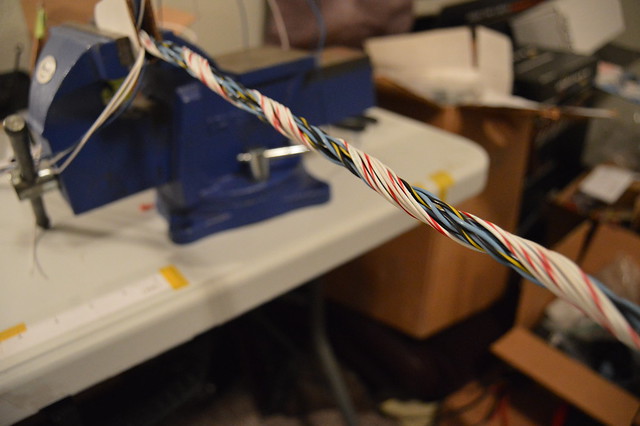
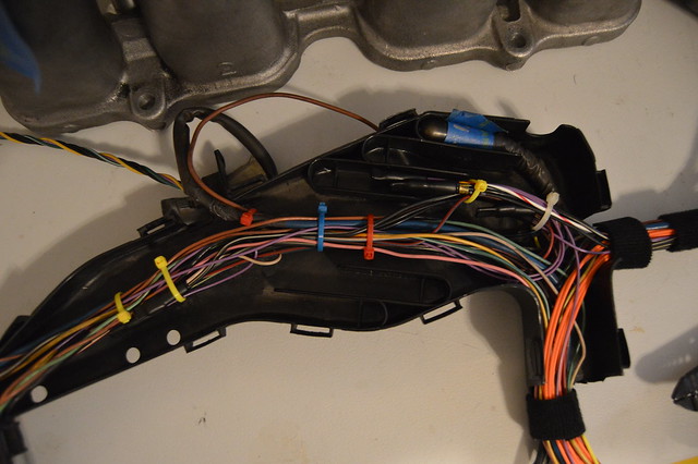
Since i was now pinning this side of the connector in a specific way to obviously match the chassis side i needed to plan out my layers here so everything goes smoothly. Now i know that spending extra time and $ to concentric twist the harness with used wire is not the most logical move but i used it as practice so i dont really care and it will still offer its benefits of flexibility along with compact packaging.
4 shielded circuit core, then inputs, then coils, then injectors
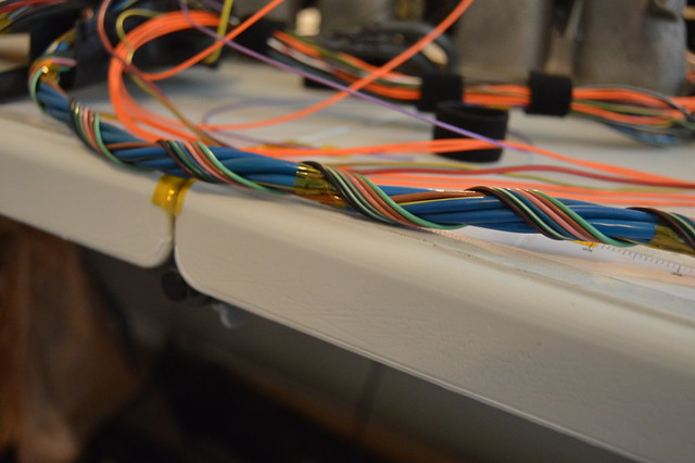
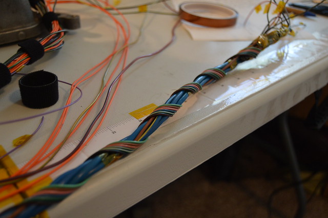
With having such a large core there was just no way i could fill out an additional layer with the number of wires i was dealing with. So i left it at this and heatshrunk it. Also ran 2 additional circuits for possible input/ output expansion in the future.
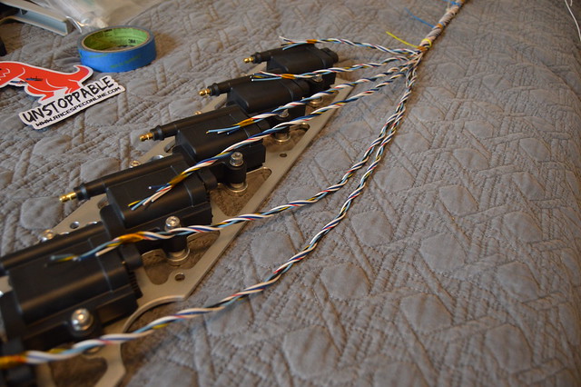
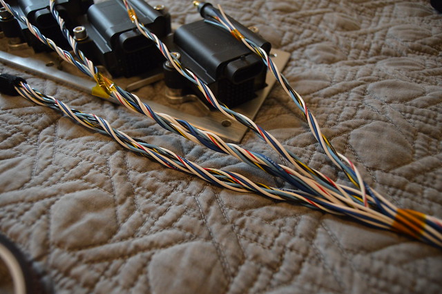
And this is 99% wired up with everything tucked nicely. I have 4 circuits branching to the OEM fuse box which i need to find a home for to supply 12V to the injectors, coils, IAC, VVTI, and ethanol sensor.
4 shielded circuit core, then inputs, then coils, then injectors
With having such a large core there was just no way i could fill out an additional layer with the number of wires i was dealing with. So i left it at this and heatshrunk it. Also ran 2 additional circuits for possible input/ output expansion in the future.
And this is 99% wired up with everything tucked nicely. I have 4 circuits branching to the OEM fuse box which i need to find a home for to supply 12V to the injectors, coils, IAC, VVTI, and ethanol sensor.
Quick question from a guy who knows very little about wiring. When you twist all those wires around core wire bunch, won't that make it extremely difficult in the future if you have an issue with a specific wire? I know its mostly all new wire and locating a problem wire would be easy but if theres a break someday in a core wire there would be a lot of work involved getting to it. why not run straight wires and just heatshrink plus loom that, would that be less effective somehow?
Thread Starter
Full Member
Joined: Nov 2013
Posts: 94
Likes: 2
From: NY
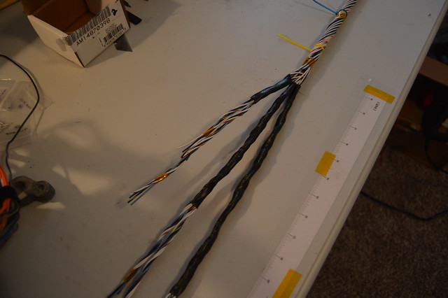
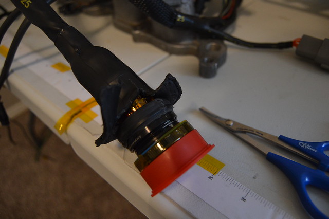
After finishing up wrapping the engine side harness i decided it was too long for my liking after it was fully terminated so i depinned the entire connector and snipped it. second run came out much better minus the interference with the shrink boot. Already have it set at 90* and clearance/ harness slack is perfect.
picture dump of some heatshrink added to various legs of the oem harness and new circuits
final resistance check to verify all pins are correct. this was from ecu connector to each component connector.
got the ignition harness completed as well. Splice work here
picture dump of some heatshrink added to various legs of the oem harness and new circuits
final resistance check to verify all pins are correct. this was from ecu connector to each component connector.
got the ignition harness completed as well. Splice work here
Thread Starter
Full Member
Joined: Nov 2013
Posts: 94
Likes: 2
From: NY
and finished up with a DTP. not the cleanest work but functional and room for expansion/ modification in the future.

And size difference between a size 12 contact and size 20.
Need to terminate the other side and run to switched 12V, and ground.
Finished harness which needs the 90* boot before its all done
I read a good article on ECU grounding which led to me adding a busbar for the ECU grounds which i will ground to the engine block as opposed to battery negative.
Thread Starter
Full Member
Joined: Nov 2013
Posts: 94
Likes: 2
From: NY
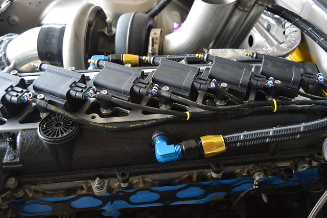
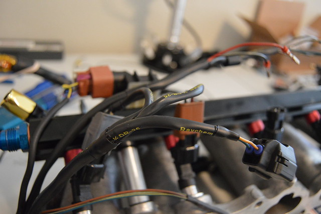
Lets get all caught up! The engine harness is complete after making some last minute changes due to fitment with the intake manifold. Cut off the straight boot and reorientated the harness for a 90* boot which worked out perfect. Also depinned all the injector connectors and added raychem to those circuits.
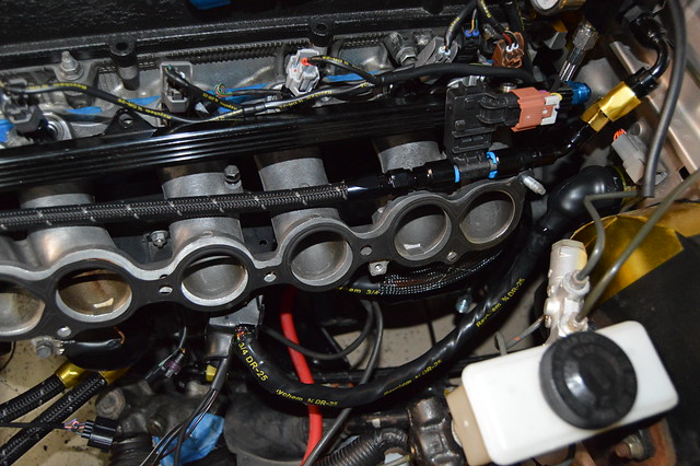
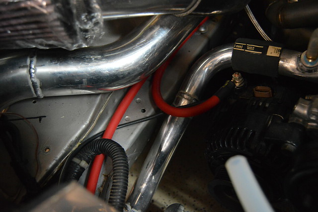
With this mainly completed, it was time to run battery cable so i could find my switched 12V sources to fully finish up this harness and all wiring. I am using prowire usa motorsports battery cable which is very flexible and a better suited option than welding cable. 2ga used here. As i mentioned before, i am running a 2ga from the battery + to this firewall bulkhead.
From there, i ran a 2ga to the alternator and then another 2ga to the starter. There is then a 6ga running from the alternator post to the OEM underhood fusebox
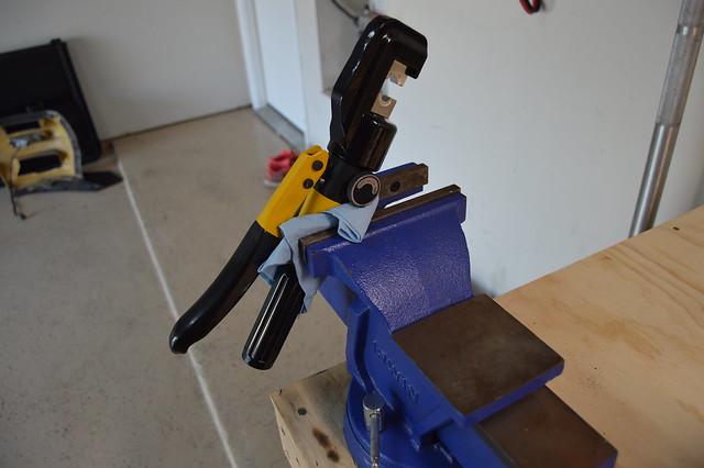
I purchased this 10 ton hydraulic crimper (betool brand) for 40 bucks of amazon (best reviews in comparison of the others) and am very happy with it.
And finished product-
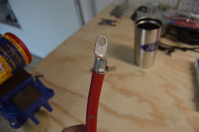
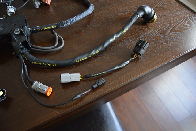
i have been finishing these off with DR25 when using a rubber boot or with SCL adhesive lined when running without the boot.
With this mainly completed, it was time to run battery cable so i could find my switched 12V sources to fully finish up this harness and all wiring. I am using prowire usa motorsports battery cable which is very flexible and a better suited option than welding cable. 2ga used here. As i mentioned before, i am running a 2ga from the battery + to this firewall bulkhead.
From there, i ran a 2ga to the alternator and then another 2ga to the starter. There is then a 6ga running from the alternator post to the OEM underhood fusebox
I purchased this 10 ton hydraulic crimper (betool brand) for 40 bucks of amazon (best reviews in comparison of the others) and am very happy with it.
And finished product-
i have been finishing these off with DR25 when using a rubber boot or with SCL adhesive lined when running without the boot.
Thread Starter
Full Member
Joined: Nov 2013
Posts: 94
Likes: 2
From: NY
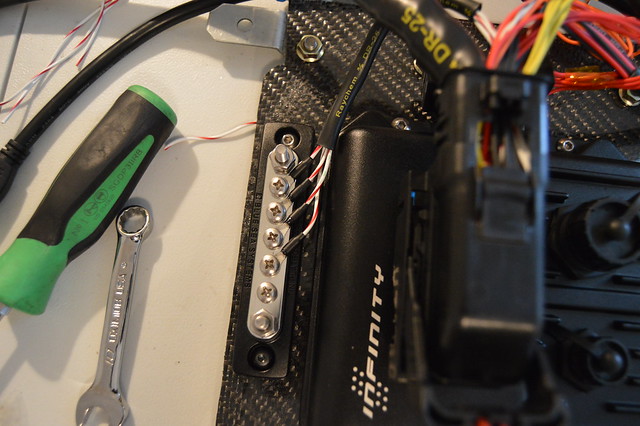
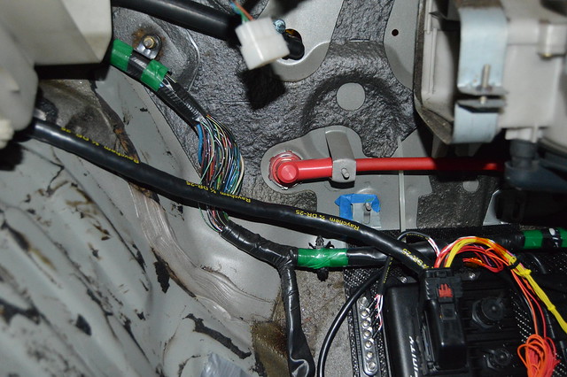
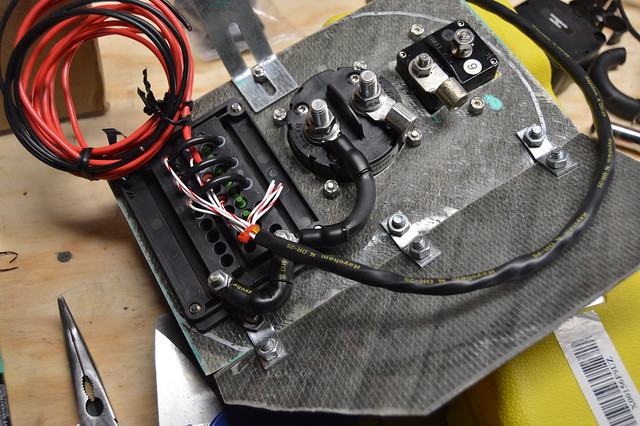
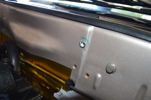
Due to packaging i ended up remaking the upper power distribution panel. The 200A breaker is set between the battery + and the 2ga cable to the firewall. The interrupt switch is set between the battery + and the bussman fuse box which powers the fuel pump and ECU. I chose this method so i can hit the interrupt switch and it will power down the ECU and kill fuel. Tripping the 200A breaker only risks a voltage spike from the alternator and also the possibility of the alternator powering the fuse box without the battery.
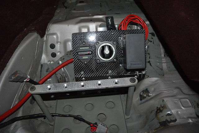

Backside- 6ga power cable from the interrupt switch and between the bussman posts.
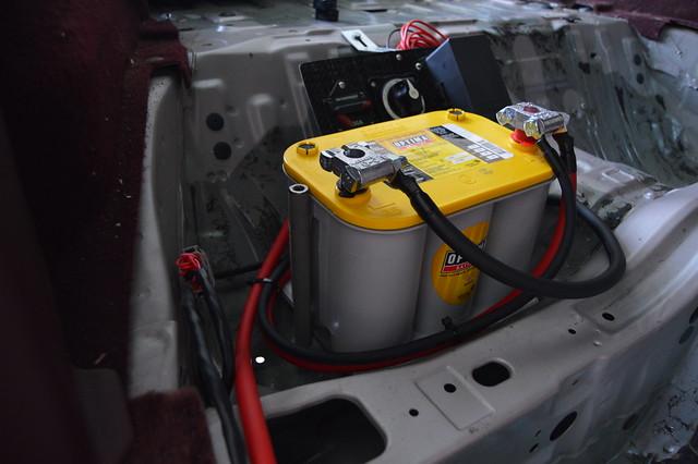
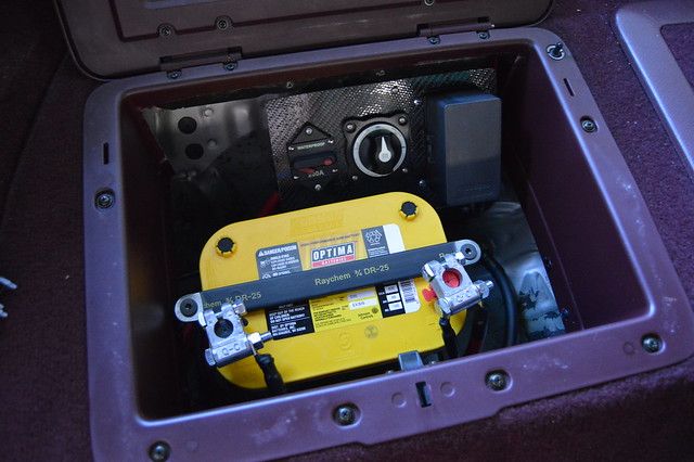
Picked up a D35 yellow top and finished up with power/ ground cables. I chose to use the rear seat seatbelt threaded hole for my ground and of course cleaned all grounds to bare metal. From the engine block to battery negative im at .04 ohms.
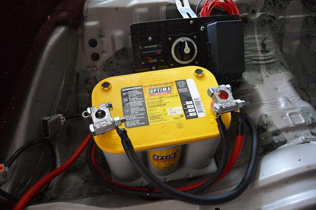
Wish i didnt have to cross the cables like this but the posts were practically touching the cross bar when oriented the other way.
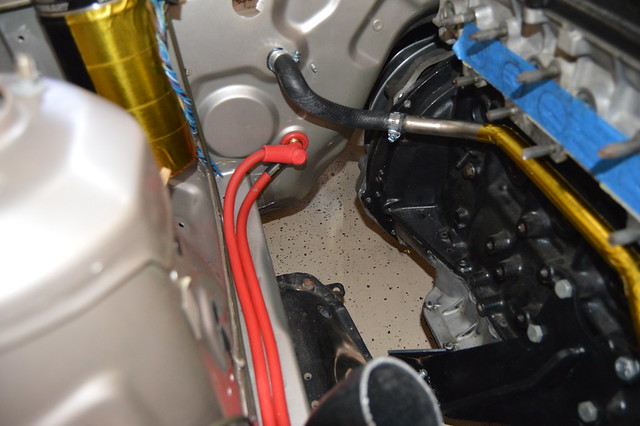
Also got all my engine grounds made. I went with a 2ga running from the starter body/transmission bellhousing to frame rail and a 6ga from the block to frame rail on the starter side of the engine. On the other side, i ran a 6ga from the block to firewall and will be adding a 2ga from the alternator housing to the frame rail. I will also add another 6ga from the cylinder head to firewall.
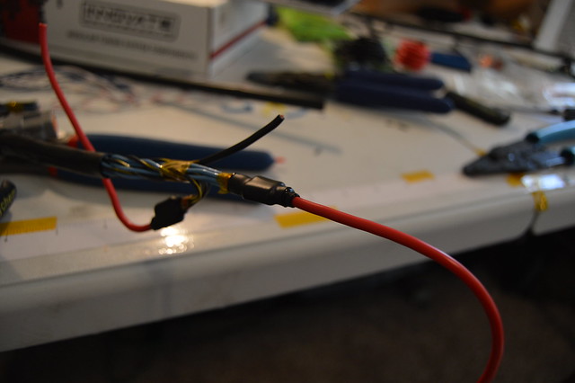
With that all handled i ran some temporary splices for the wideband gauge and flipped the switch

This was a milestone for this build as i am getting so damn close to firing it up. I am placing an order this week for some more splices and ring terminals so i can finish up the ECU ground and wire my switched 12V inputs inside the cab. I will also be probing around the engine side connectors to find switched 12V for the coils, injectors, IAC/VVTI, and then wire up the fans.
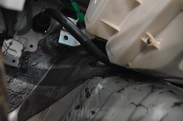
Non wiring related, i finished plumbing my heater lines

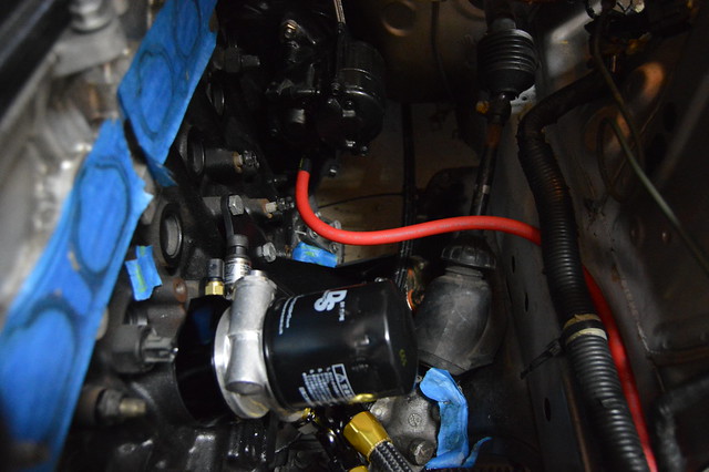
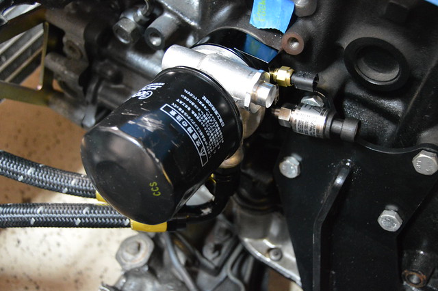
Not sure if i added this but installed my sandwhich plate for oil pressure/temp
Backside- 6ga power cable from the interrupt switch and between the bussman posts.
Picked up a D35 yellow top and finished up with power/ ground cables. I chose to use the rear seat seatbelt threaded hole for my ground and of course cleaned all grounds to bare metal. From the engine block to battery negative im at .04 ohms.
Wish i didnt have to cross the cables like this but the posts were practically touching the cross bar when oriented the other way.
Also got all my engine grounds made. I went with a 2ga running from the starter body/transmission bellhousing to frame rail and a 6ga from the block to frame rail on the starter side of the engine. On the other side, i ran a 6ga from the block to firewall and will be adding a 2ga from the alternator housing to the frame rail. I will also add another 6ga from the cylinder head to firewall.
With that all handled i ran some temporary splices for the wideband gauge and flipped the switch
This was a milestone for this build as i am getting so damn close to firing it up. I am placing an order this week for some more splices and ring terminals so i can finish up the ECU ground and wire my switched 12V inputs inside the cab. I will also be probing around the engine side connectors to find switched 12V for the coils, injectors, IAC/VVTI, and then wire up the fans.
Non wiring related, i finished plumbing my heater lines
Not sure if i added this but installed my sandwhich plate for oil pressure/temp
Thread Starter
Full Member
Joined: Nov 2013
Posts: 94
Likes: 2
From: NY
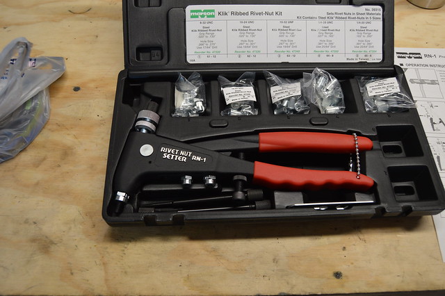
ordered this rivnut tool (marson RN1) and mounted my FRP higher so i could finish my return line plumbing
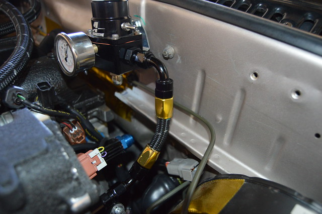
And then got my fuel line mounting/ routing finished up. I had to revise this since the fab shop welded the crossmember brackets. Much happier with this option as its isolated from the chassis. BTW found these decent billet separators on ebay. 8 pcs for $26 as opposed to $12 a piece on jegs. Drilled them out for larger hardware and used nylon bushings
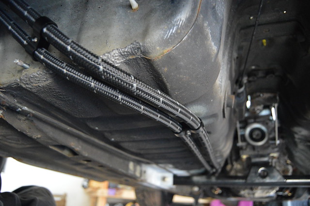
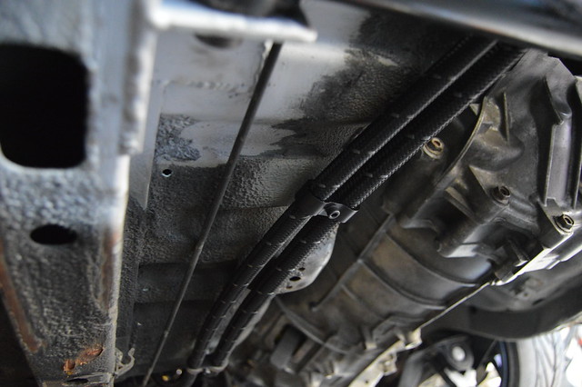

Still need to order 3 more feet of -6 and fittings for the pump hanger return line.
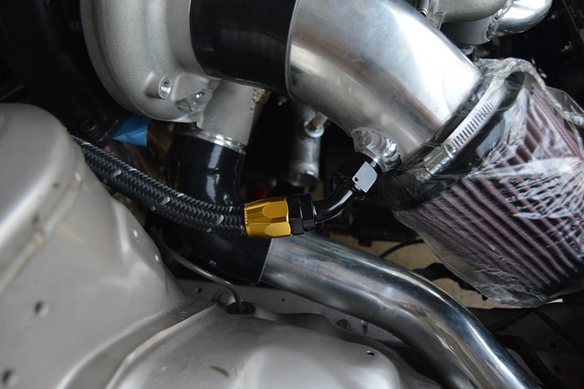
Went with some PTFE -8 for the pump hanger. Hopefully i dont run into any issues using this method but after the fact i found some submersible PTFE line on radium engineerings website.
Picked up some -10 separators as well for catchcan and oil cooler lines.
At some point i lowered her back down a little in attempt to build motivation (it worked)

And then got my fuel line mounting/ routing finished up. I had to revise this since the fab shop welded the crossmember brackets. Much happier with this option as its isolated from the chassis. BTW found these decent billet separators on ebay. 8 pcs for $26 as opposed to $12 a piece on jegs. Drilled them out for larger hardware and used nylon bushings
Still need to order 3 more feet of -6 and fittings for the pump hanger return line.
Went with some PTFE -8 for the pump hanger. Hopefully i dont run into any issues using this method but after the fact i found some submersible PTFE line on radium engineerings website.
Picked up some -10 separators as well for catchcan and oil cooler lines.
At some point i lowered her back down a little in attempt to build motivation (it worked)
Thread Starter
Full Member
Joined: Nov 2013
Posts: 94
Likes: 2
From: NY
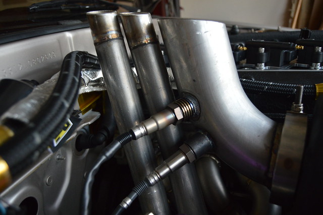
And then spent an hour cleaning metal shavings from my intercooler pipes and coolant pipes. Not too happy about that but this is what happens when you dont do things yourself. This is how i got all the piping back and there is some sitting in my intercooler which i will have to flush. I used cut up microfiber towels and pushed them through the piping with extensions and then using water from the hose
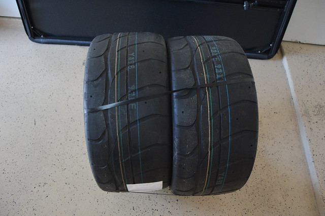
Scooped up some 265/40/18 NT01's as wel. Might mount these after the texas "winter" since they apparently dont like temps below freezing.
After i get my switched 12V wired up and everything back together i will order my basetune and get some new sparkplugs. Then i can pick up fluids and order a driveshaft before i can drive her!!!!!!
Thread Starter
Full Member
Joined: Nov 2013
Posts: 94
Likes: 2
From: NY
Quick question from a guy who knows very little about wiring. When you twist all those wires around core wire bunch, won't that make it extremely difficult in the future if you have an issue with a specific wire? I know its mostly all new wire and locating a problem wire would be easy but if theres a break someday in a core wire there would be a lot of work involved getting to it. why not run straight wires and just heatshrink plus loom that, would that be less effective somehow?
Catching this thread up copy/paste style!
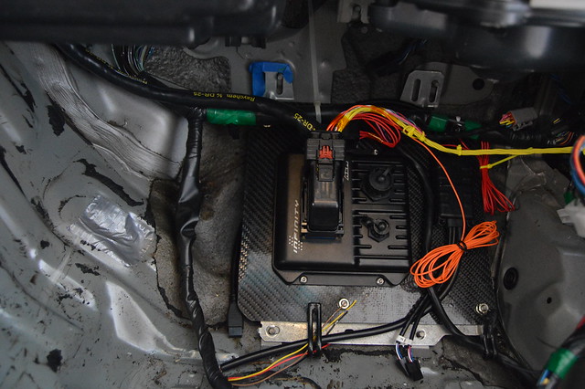
Update time! Got in hopefully what is my last order from racespec. More splices, ring terminals, and a DTP 4 pin connector. Here is the completed engine harness which includes plug and play jumper harnesses for the mazda connector for switched 12V and the starter solenoid.
this is the coil pack sub harness which includes cylinder head ground, 12V ground (grounded at block), and 12V+. I wired in a new relay using the open ABS bus bar in the OEM fuse box and triggered by a mazda keyed 12V source. Small harness is the switched 12V jumper for injectors, VVTI, IAC, and alternator
and installed
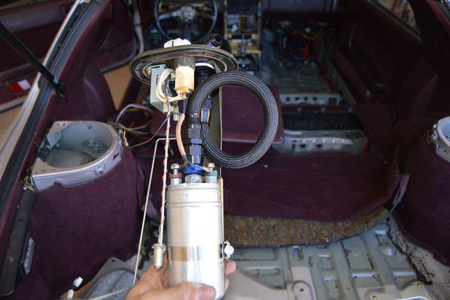
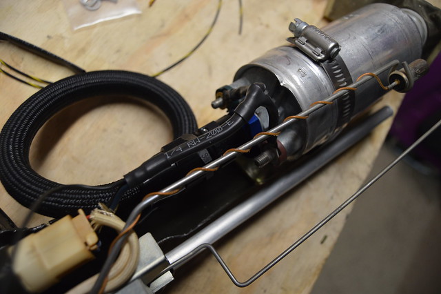
The other thing i was waiting on was ring terminals for the fuel pump and other assorted things. Fuel pump is now all complete and wired up. This is raychem RW-200 which is fuel cell spec heatshrink.
Trimmed up the cubby and got the battery tie down heatshrinked since it was pretty close to my terminals.
I powered everything up again and confirmed that i have 12V where i need it and that the starter solenoid got power (bypassed the security module).
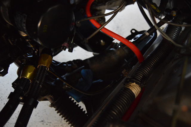
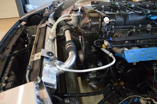
Used some spare hardline for a cleaner coolant line running to the swirl pot. This is the second highest point in the head other than the rear heater core outlet.
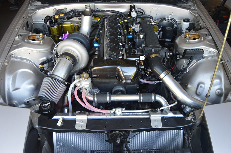
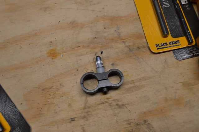
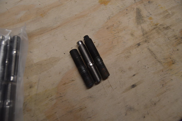
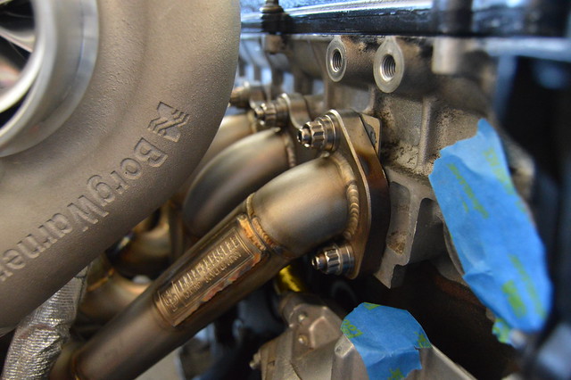
Ordered some titanium exhuast studs from fuse fab (same guy who built my manifold) and then spent 3 hours getting this silly manifold on. basically, due to them being 12PT 13MM nuts, it was near impossible to tighten the rear bottom 2 nuts as they were making contact with the runner. I ended up using 2 nuts and the Ti washers so i could just use an open end to tighten them. Also attempted to make a tool but it didnt work out.

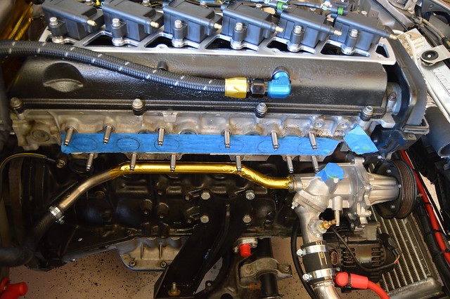
Comparison of my cut studs, the OEM, and the Ti
Thread Starter
Full Member
Joined: Nov 2013
Posts: 94
Likes: 2
From: NY
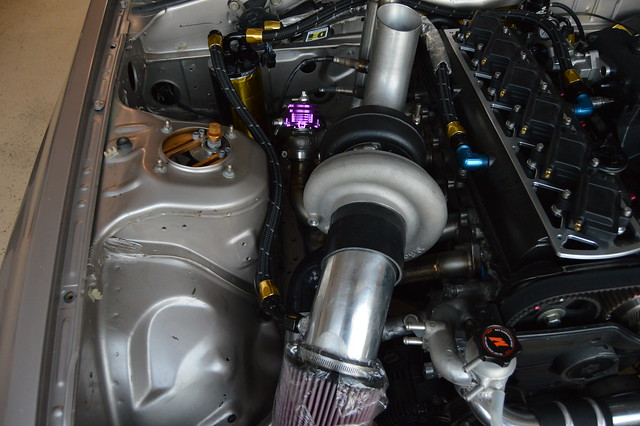
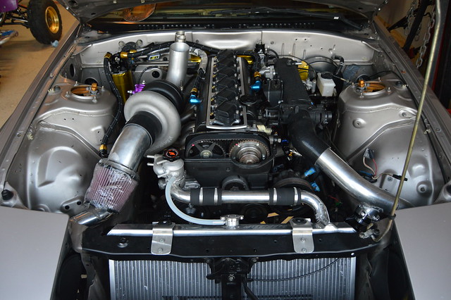
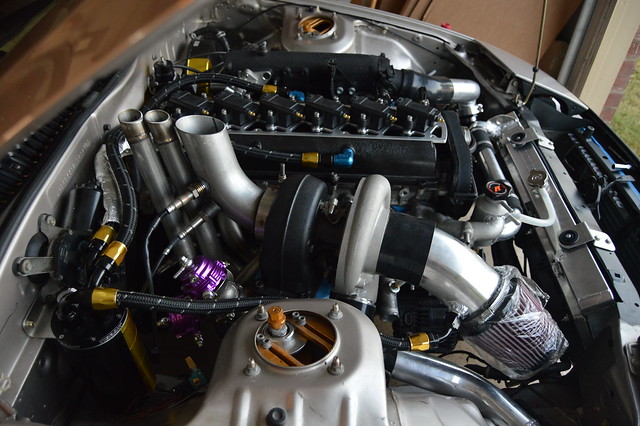
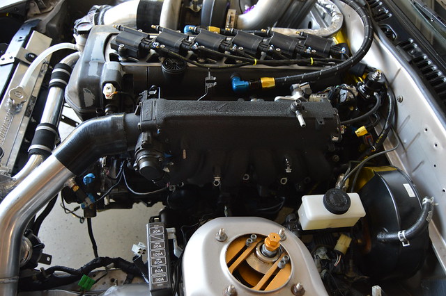
And finally all mounted and torqued
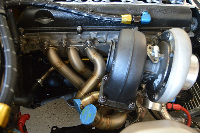
Hotside all torqued to spec for hopefully the last time.
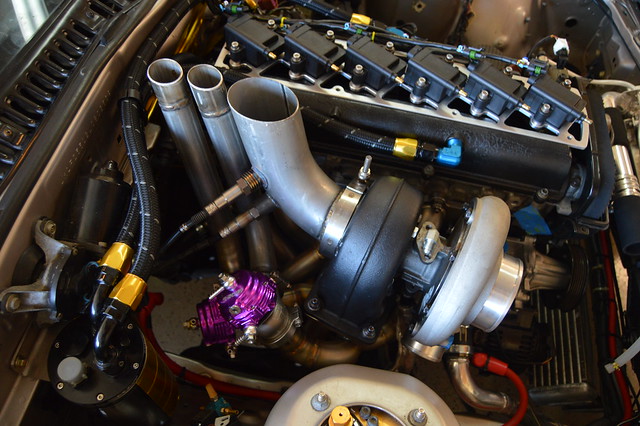
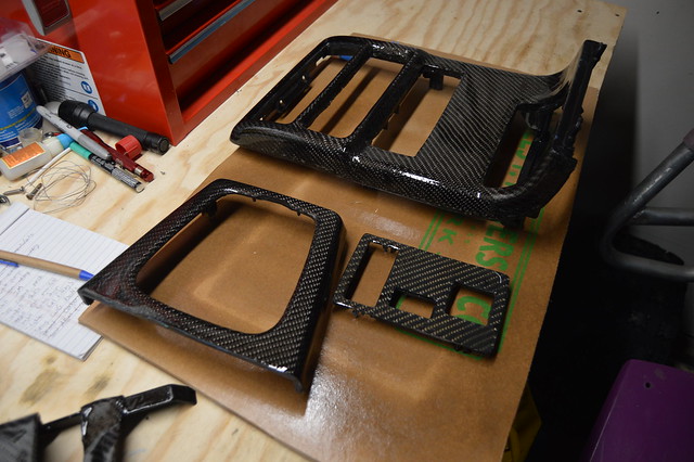
5 months later.. finally got around to clear coating my carbon bits since it was so nice out
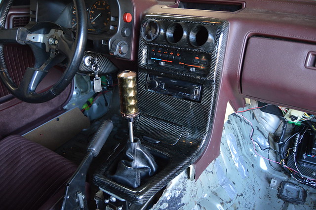
How she sits now. ordered plugs and a serp belt then have to pressure test the cooling system, flush the fuel lines, fill her up with fluids, then prime the turbo. I also powered up my AEM infinity to load the latest firmware. I have a base tune being worked on by Vlad and have spoken to a local driveshaft shop about building me a steel shaft (to hold me over until i go 8.8 kit). We are getting pretty close to hearing this thing for the first time!! Once it is running without any bugs i will buy a master cylinder and clutch line so i can drive her around before registering it in TX.
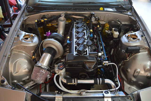
Hotside all torqued to spec for hopefully the last time.
5 months later.. finally got around to clear coating my carbon bits since it was so nice out
How she sits now. ordered plugs and a serp belt then have to pressure test the cooling system, flush the fuel lines, fill her up with fluids, then prime the turbo. I also powered up my AEM infinity to load the latest firmware. I have a base tune being worked on by Vlad and have spoken to a local driveshaft shop about building me a steel shaft (to hold me over until i go 8.8 kit). We are getting pretty close to hearing this thing for the first time!! Once it is running without any bugs i will buy a master cylinder and clutch line so i can drive her around before registering it in TX.
Junior Member
Joined: May 2017
Posts: 23
Likes: 0
From: Portland Oregon
Beautiful Work man i'm in the process of building a drift FC as well ... I decided on keeping my 13b for now but man ... this ... this is a true work of art ... that wiring job ... MMMMM so many good bits ... don't be mad if i steal some ideas ;P
On a side note which sandwich plate did you go with? I've been looking at the Mishimoto one for a while. Seems like a simple and attractive way to get some extra oil lines.
Cant wait to see more!
On a side note which sandwich plate did you go with? I've been looking at the Mishimoto one for a while. Seems like a simple and attractive way to get some extra oil lines.
Cant wait to see more!
Thread Starter
Full Member
Joined: Nov 2013
Posts: 94
Likes: 2
From: NY
Beautiful Work man i'm in the process of building a drift FC as well ... I decided on keeping my 13b for now but man ... this ... this is a true work of art ... that wiring job ... MMMMM so many good bits ... don't be mad if i steal some ideas ;P
On a side note which sandwich plate did you go with? I've been looking at the Mishimoto one for a while. Seems like a simple and attractive way to get some extra oil lines.
Cant wait to see more!
On a side note which sandwich plate did you go with? I've been looking at the Mishimoto one for a while. Seems like a simple and attractive way to get some extra oil lines.
Cant wait to see more!

Thread Starter
Full Member
Joined: Nov 2013
Posts: 94
Likes: 2
From: NY
Damn these forums are dead. This thing runs and drives and is currently partially tuned. Started running into some fuel pressure issues and will be installing the built2apex dual pump setup shortly.