Canadian Forum Canadian users, post event and club info here.

Because The 20B Is So Last Year...

Thread Tools
 
Search this Thread
 
Old Oct 18, 2007 | 12:50 PM
  #1  
Aaron Cake's Avatar
Thread Starter
Engine, Not Motor
Tenured Member: 20 Years
iTrader: (1)
 
Joined: Feb 2001
Posts: 29,798
Likes: 128
From: London, Ontario, Canada
Because The 20B Is So Last Year...

Anyone have any good turbo recommendations to be used with this?


Reply
Old Oct 18, 2007 | 12:54 PM
  #2  
RacerJason's Avatar
Coming to a track near u!
Tenured Member 15 Years
iTrader: (5)
 
Joined: Sep 2001
Posts: 3,858
Likes: 3
From: Toronto
*yawn* Is that the best you can do?

But seriously... Holy schnikeees. Always raising the bar that long haired Londoner.

I'd slap it in a N/A PP and let it howl!!
Reply
Old Oct 18, 2007 | 01:21 PM
  #3  
Alak's Avatar
Eats, Sleeps, Dreams Rotary
Tenured Member: 20 Years
iTrader: (9)
 
Joined: Sep 2004
Posts: 3,040
Likes: 0
From: Canada
Originally Posted by Aaron Cake
Anyone have any good turbo recommendations to be used with this?
I recommend a Mohaghany coffin.


I have to ask if thats the real deal, because last time I inquired about a real Mazda MFR e-shaft, I was told close to $100,000 used and he wasn't joking.
Reply
Old Oct 18, 2007 | 01:42 PM
  #4  
IAN's Avatar
IAN
Rotary Reborn!
Tenured Member 20 Years
iTrader: (3)
 
Joined: Mar 2001
Posts: 5,284
Likes: 9
From: Canada
Quit Teasing!
Reply
Old Oct 18, 2007 | 02:04 PM
  #5  
Neo's Avatar
Neo
Eats, Sleeps, Dreams Rotary
Tenured Member: 25 Years
Liked
Loved
Community Favorite
iTrader: (5)
 
Joined: Feb 2001
Posts: 4,001
Likes: 379
From: Aurora, Ontario, Canada
Aaron is going to compete with Scoot over who has the best quad rotor! lol
Reply
Old Oct 18, 2007 | 02:27 PM
  #6  
Nismo Convert86's Avatar
400WHP or bust
Tenured Member 15 Years
iTrader: (7)
 
Joined: Oct 2003
Posts: 4,048
Likes: 0
From: Walkerton, Ontario Canada
It's going to take him wayyyyy too long to get this going too, I bet 5 others beat him to it...
Reply
Old Oct 18, 2007 | 02:27 PM
  #7  
Japan2LA's Avatar
Banned. I got OWNED!!!
iTrader: (256)
 
Joined: Mar 2005
Posts: 11,089
Likes: 2
From: Los Angeles CA.
Nice, two 13B shafts joined together...
Reply
Old Oct 18, 2007 | 08:28 PM
  #8  
R.P.M.'s Avatar
Likes to swear....alot
Tenured Member 15 Years
iTrader: (3)
 
Joined: Dec 2002
Posts: 3,791
Likes: 3
From: Kitchener Ontario Canada
Hey Aaron....I hope that is a multi peice shaft.....cause it looks pretty awkward to have to keep sliding irons over all those lobes lol.

So why isn't it built yet? j/k!
Reply
Old Oct 19, 2007 | 10:49 AM
  #9  
Aaron Cake's Avatar
Thread Starter
Engine, Not Motor
Tenured Member: 20 Years
iTrader: (1)
 
Joined: Feb 2001
Posts: 29,798
Likes: 128
From: London, Ontario, Canada
Originally Posted by racerjason
*yawn* Is that the best you can do?
But seriously... Holy schnikeees. Always raising the bar that long haired Londoner.
I'd slap it in a N/A PP and let it howl!!
That's basically the plan. Peripheral port NA with S5 rotors, dry sump, etc. I've had the intake design in my head for a long time and as straightforward and unoriginal as it is, it's going to be a very nice manifold regardless. The exhaust will be a bit more interesting.

Originally Posted by Alak
I recommend a Mohaghany coffin.
I have to ask if thats the real deal, because last time I inquired about a real Mazda MFR e-shaft, I was told close to $100,000 used and he wasn't joking.
It's not an original 3 piece Mazda shaft. The Mazda 4 rotor shaft is 3 piece with a main bearing to support each rotor. Most homemade and aftermarket shafts are two piece and use only three main bearings to keep the cost and length of the engine down.

Originally Posted by R.P.M.
Hey Aaron....I hope that is a multi peice shaft.....cause it looks pretty awkward to have to keep sliding irons over all those lobes lol.
So why isn't it built yet? j/k!
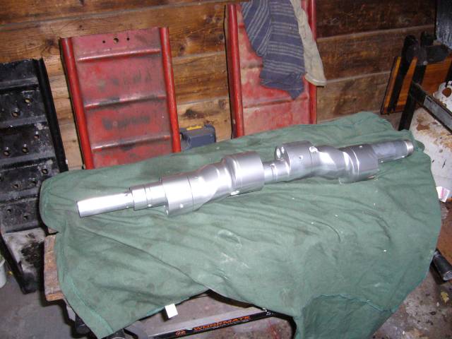
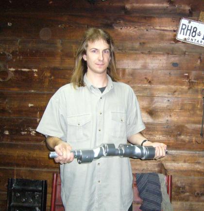
This shaft is sort of a mockup or prototype for the final version. As such, this particular shaft will never see the inside of an engine. It was a very worthwhile exercise because it's really cleared up the methods of joining eccentrics. It's one thing to think about it for almost 7 years, but quite another to actually put your hands on some shafts and start tinkering. I'd say that any machine shop worth it's salt is capable of making a 4 rotor eccentric from two 13B eccentrics for less then $1000. The thick center bearing iron is actually the challenge, but not huge...
Reply
Old Oct 19, 2007 | 11:25 AM
  #10  
Nick86's Avatar
Yup, still here
Tenured Member: 20 Years
iTrader: (1)
 
Joined: May 2002
Posts: 3,053
Likes: 2
From: Ottawa
While I know this will probably be intended for Tiina (have to rename her!)... tell us, do you get an evil grin when you look at this and your newly acquired RX-5 cosmo together? That'd be one hell of an original pairing!
Reply
Old Oct 19, 2007 | 01:01 PM
  #11  
Alak's Avatar
Eats, Sleeps, Dreams Rotary
Tenured Member: 20 Years
iTrader: (9)
 
Joined: Sep 2004
Posts: 3,040
Likes: 0
From: Canada
Originally Posted by Aaron Cake
It's one thing to think about it for almost 7 years, but quite another to actually put your hands on some shafts and start tinkering.
Reply
Old Oct 19, 2007 | 04:06 PM
  #12  
silverrotor's Avatar
Moderator
Tenured Member: 20 Years
iTrader: (1)
 
Joined: Mar 2002
Posts: 7,592
Likes: 5
From: Toronto, Corporate Canada
It's about time you brought this Into light. You've been dragging this Idea for awhile now. Take my 20B. Think for tomorrow - not last year.
Reply
Old Oct 19, 2007 | 05:23 PM
  #13  
brent clement's Avatar
Fabricator and builder
Tenured Member 10 Years
 
Joined: Jun 2003
Posts: 936
Likes: 0
From: Innisfil, Ontario
Sounds cool Aaron, so how's this one held together? Is it a taper and key?
Reply
Old Oct 20, 2007 | 10:12 AM
  #14  
Aaron Cake's Avatar
Thread Starter
Engine, Not Motor
Tenured Member: 20 Years
iTrader: (1)
 
Joined: Feb 2001
Posts: 29,798
Likes: 128
From: London, Ontario, Canada
Originally Posted by Nick86
While I know this will probably be intended for Tiina (have to rename her!)... tell us, do you get an evil grin when you look at this and your newly acquired RX-5 cosmo together? That'd be one hell of an original pairing!
Definitely Tina's next engine (or perhaps 2nd next because I want to try a full bridge 6 port 13B). I have a functioning 13B from a GSL-SE that will go into the Cosmo after a rebuild and street port. I've been flip flopping as to whether or not to use the 20B since it's the modern Eunos Cosmo engine but then I have to cut and hack the car. Also how much power does it need really? The 4 port 13B it came with can't be more then 120HP and I don't think I've ever heard anyone say those cars are underpowered. What I don't want to create is a difficult to drive monster that has 500HP of unusable power. I want a turn-key car that almost anyone can drive, with decent mileage, quiet exhaust and a slight bit of go when necessary.

Originally Posted by brent clement
Sounds cool Aaron, so how's this one held together? Is it a taper and key?
Mazda of course uses a taper and key which is probably the best way to do it. But it's hard for a "backyard engineer" to create a good taper that will be precise enough. In my opinion, the best way to create a backyard 4 rotor shaft is to use a set of splines. The Mazda piece already provides a thinner snout that will fit into the rear of the "front" shaft after the hole (which is conveniently perfectly centered...) for the oil passage is bored out. The end of the spline then seals with an o-ring. Most machine shops can create splines without any issue, as can better driveline shops. The key is keeping the lobe phasing at exactly 90 degrees but as luck would have it, the lightening holes in the lobes are very convenient as a reference for jigging.
Reply
Old Oct 20, 2007 | 04:40 PM
  #15  
Alak's Avatar
Eats, Sleeps, Dreams Rotary
Tenured Member: 20 Years
iTrader: (9)
 
Joined: Sep 2004
Posts: 3,040
Likes: 0
From: Canada
What about a 13B-RE for the Cosmo? Would be mighty nice with a set of twins.
Reply
Old Oct 20, 2007 | 11:40 PM
  #16  
captain carnage's Avatar
Full Member
Tenured Member 15 Years
iTrader: (1)
 
Joined: Apr 2006
Posts: 204
Likes: 0
From: kaladar ontario
so is it a mullet or is that the lighting... at first i thought it was a massive camshaft, ive got alot to learn in this rotary game lol
Reply
Old Oct 21, 2007 | 09:41 AM
  #17  
Aaron Cake's Avatar
Thread Starter
Engine, Not Motor
Tenured Member: 20 Years
iTrader: (1)
 
Joined: Feb 2001
Posts: 29,798
Likes: 128
From: London, Ontario, Canada
Originally Posted by Alak
What about a 13B-RE for the Cosmo? Would be mighty nice with a set of twins.
That's another option but then I have to package and intercooler and all the piping. The frame rails in the Cosmo are very narrow, so much that the stock manifold only has an inch or so of clearance. And there's the mounting issue as well.

Looks like the GSL-SE 13B will bolt right in for the most part. I may need to make my own headers but that's no big deal. Also I'd like to run a cat so fuel injection is a must.
Reply
Old Oct 21, 2007 | 09:43 AM
  #18  
pfsantos's Avatar
(blank)
iTrader: (1)
 
Joined: Nov 2005
Posts: 2,285
Likes: 15
From: YYZ
Aaron, seems you're just crazy enough to make it happen and make it work well. GL and keep us posted.
Reply
Old Oct 22, 2007 | 07:15 PM
  #19  
B6T's Avatar
B6T
ERTW
Tenured Member 15 Years
iTrader: (2)
 
Joined: Nov 2004
Posts: 880
Likes: 0
From: Waterloo, Ontario
That's wicked! A four rotor shaft in Ontario! Haha.

I have a few questions about the "design". I'm assuming you're going to modify a single intermediate plate to hold the single middle bearing and you're probably going to run some sort of double sided stationary gear off that at the same location as well. So that means that single bearing is going to have to support the centrifugal force of the 4 off-balance rotors as well as the torque induced on the stat gears by two rotors. Now I haven't done any of the math to calculate the magnitude of these loads, but I would seem very cautious of leaving the single "short" bearing having to support it.

All of the four rotor shafts I've seen have four bearings. They lack the fifth bearing in the place where you have your centre bearing. This way, two rotors have a bearing on both sides, two rotors have a bearing on one side (like in an OEM rotary), and each bearing has a single stat gear.

How are the two shafts coupled?

I'm just curious as this is something I want to do as soon as I have a chance, and I want to know as much as possible before I tackle the project!
Reply
Old Oct 23, 2007 | 08:43 AM
  #20  
Aaron Cake's Avatar
Thread Starter
Engine, Not Motor
Tenured Member: 20 Years
iTrader: (1)
 
Joined: Feb 2001
Posts: 29,798
Likes: 128
From: London, Ontario, Canada
Originally Posted by B6T
I have a few questions about the "design". I'm assuming you're going to modify a single intermediate plate to hold the single middle bearing and you're probably going to run some sort of double sided stationary gear off that at the same location as well. So that means that single bearing is going to have to support the centrifugal force of the 4 off-balance rotors as well as the torque induced on the stat gears by two rotors. Now I haven't done any of the math to calculate the magnitude of these loads, but I would seem very cautious of leaving the single "short" bearing having to support it.
I've thought about that a bit as well. Scoots 4 rotor used 4 bearings, one bearing, a lobe, another bearing, two lobes, another bearing, the last lobe, then another bearing. That's a LOT of bearings and also would make the engine quite long. Though his was made up of 12A parts so that compensated for the length somewhat.

The original Mazda 2002 4 rotor design used three bearings with a majorly thick center section and a double wide bearing. They abandoned that for several reasons.

As we all know, the 787B had one bearing per rotor, but then again it was designed for endurance racing at constant high RPMs.

For a street driven 4 rotor firing at 90 degrees (instead of those "bastard" 4 rotors that fire like two 2-rotors) it should be fine. Any more bearings and the engine becomes very thick.

That said, the Kiwi-RE kit uses two "inner" main bearings, not unlike Scoot.

How are the two shafts coupled?
This shaft is a prototype mainly for exploring ways of keeping the phasing correct using backyard engineering. Interestingly enough that is very easy due to the balance holes in the lobes. They are on center and make it easy to jig. This shaft was coupled by cutting 3/4 off of the front snout of the rear shaft, cutting the flywheel taper off of the front shaft, and then boring the oil hole in the front shaft to accept the snout of the rear shaft. Then a threaded pin was used to secure.

A much improved version of that is to just bore the front shaft to accept the keyway of the rear shaft. That's probably the easiest approach.

My personal favourite would be to spline the rear shaft and front shaft to match, seal the oil passage with an o-ring at the front of the spline and then secure with pins or have a slight taper machined.

I'm just curious as this is something I want to do as soon as I have a chance, and I want to know as much as possible before I tackle the project!
I've been flip flopping the past year whether or not to go ahead and machine everything I've had down on paper for years, or just buy the Kiwi RE kit. In the end, the cost would be the same but the Kiwi kit is proven and all the hard work is done. The only disadvantage of that is I no longer have bragging rights to say that I made everything.
Reply
Old Oct 23, 2007 | 12:02 PM
  #21  
B6T's Avatar
B6T
ERTW
Tenured Member 15 Years
iTrader: (2)
 
Joined: Nov 2004
Posts: 880
Likes: 0
From: Waterloo, Ontario
Originally Posted by Aaron Cake
I've thought about that a bit as well. Scoots 4 rotor used 4 bearings, one bearing, a lobe, another bearing, two lobes, another bearing, the last lobe, then another bearing. That's a LOT of bearings and also would make the engine quite long. Though his was made up of 12A parts so that compensated for the length somewhat.
There would be no difference in length since the bearings are all housed within the centre bore of the intermediate irons, or at least they are that way in all multi rotor applications I've seen. The length of the engine is determined by the types of rotor housings obviously (12A or 13B), but your 50mm intermediate plates are always going to be the same width whether there is a bearing in them or not. If you take a look at the centre plate bearing modifications that Jeff Bruce does, then you'll know what I mean. But I'm assuming you're going to be using a modified centre iron to house your centre bearing, a la Jeff Bruce (and Steve from MPS... if you need local help with the machine work from someone who knows these things inside and out), but I could be off on this assumption. Perhaps you have something else in mind as a bearing carrier that's different from what's be traditionally used.

My personal favourite would be to spline the rear shaft and front shaft to match, seal the oil passage with an o-ring at the front of the spline and then secure with pins or have a slight taper machined.
That's a good idea, but how are you going to hold them together? The only option I can think of would be to thread the end of one shaft and have a long tension bolt running through the centre of the shaft. But then you may run into oil supply problems with that.
Reply
Old Oct 23, 2007 | 12:44 PM
  #22  
R.P.M.'s Avatar
Likes to swear....alot
Tenured Member 15 Years
iTrader: (3)
 
Joined: Dec 2002
Posts: 3,791
Likes: 3
From: Kitchener Ontario Canada
I was wondering the same thing...there shouldn't be any difference in the engine length if you used 5 bearings (whic his what I would want to do). Have a bearing supporting the e-shaft in between each rotor.
Reply
Old Oct 23, 2007 | 02:42 PM
  #23  
Aaron Cake's Avatar
Thread Starter
Engine, Not Motor
Tenured Member: 20 Years
iTrader: (1)
 
Joined: Feb 2001
Posts: 29,798
Likes: 128
From: London, Ontario, Canada
Originally Posted by B6T
There would be no difference in length since the bearings are all housed within the centre bore of the intermediate irons, or at least they are that way in all multi rotor applications I've seen. The length of the engine is determined by the types of rotor housings obviously (12A or 13B), but your 50mm intermediate plates are always going to be the same width whether there is a bearing in them or not. If you take a look at the centre plate bearing modifications that Jeff Bruce does, then you'll know what I mean.
Are you referring to the center plates that would be used with two piece eccentric shafts?

It's a bit of a brain fart on my part, but by thicker I keep thinking of two main bearings side to side like the 2002.

Another one of my plans was to machine a thick center iron like the 20B and have the engine assembled in two halves (two sets of tension bolts both meeting on the center most plate. But for obvious reasons this is a stupid idea.

But I'm assuming you're going to be using a modified centre iron to house your centre bearing, a la Jeff Bruce (and Steve from MPS... if you need local help with the machine work from someone who knows these things inside and out),
I've already got this one figured out. The original plan was to machine a new center plate from scratch, but its far easier to machine a double ended stationary gear with bearing to fit perfectly within the opening of a stock center plate. Then pin it from the sides much like the rotor stationary gears. It's then easy to feed oil to it via a line that follows the stock filler passage.

but I could be off on this assumption. Perhaps you have something else in mind as a bearing carrier that's different from what's be traditionally used.
Just me being confused thinking of three different engines at once. Right now my mind is full of 4 rotor thoughts, going over what I've been thinking about years back and adding new ideas.

That's a good idea, but how are you going to hold them together? The only option I can think of would be to thread the end of one shaft and have a long tension bolt running through the centre of the shaft. But then you may run into oil supply problems with that.
Long hollow bolt. If it is clearanced to fit within the larger bore, there will be no vibration issues.

The only reason I would want to stay away from tapers is that they are hard to machine for the backyard builder.
Reply
Old Oct 25, 2007 | 05:48 PM
  #24  
orion84gsl's Avatar
My 7 is my girlfriend.
Tenured Member 10 Years
iTrader: (5)
 
Joined: Feb 2006
Posts: 3,162
Likes: 1
From: London, Ontario, Canada
Nice to see you finally got that thing into one solid piece.
Reply
Old Oct 25, 2007 | 06:21 PM
  #25  
McTinkerson's Avatar
Leave it Stock?!
Tenured Member 15 Years
 
Joined: Jun 2006
Posts: 71
Likes: 0
From: The magical land of No Emissions
Eagerly looking forward to this one, but with this project in it's early stages now. What's going to happen the that short throw shifter you were working on?
Reply


All times are GMT -5. The time now is 01:38 PM.