When you click on links to various merchants on this site and make a purchase, this can result in this site earning a commission. Affiliate programs and affiliations include, but are not limited to, the eBay Partner Network.
The eeby-sleeby fairy came and curbstomped the daylights out of me before I could post last night, or something like that
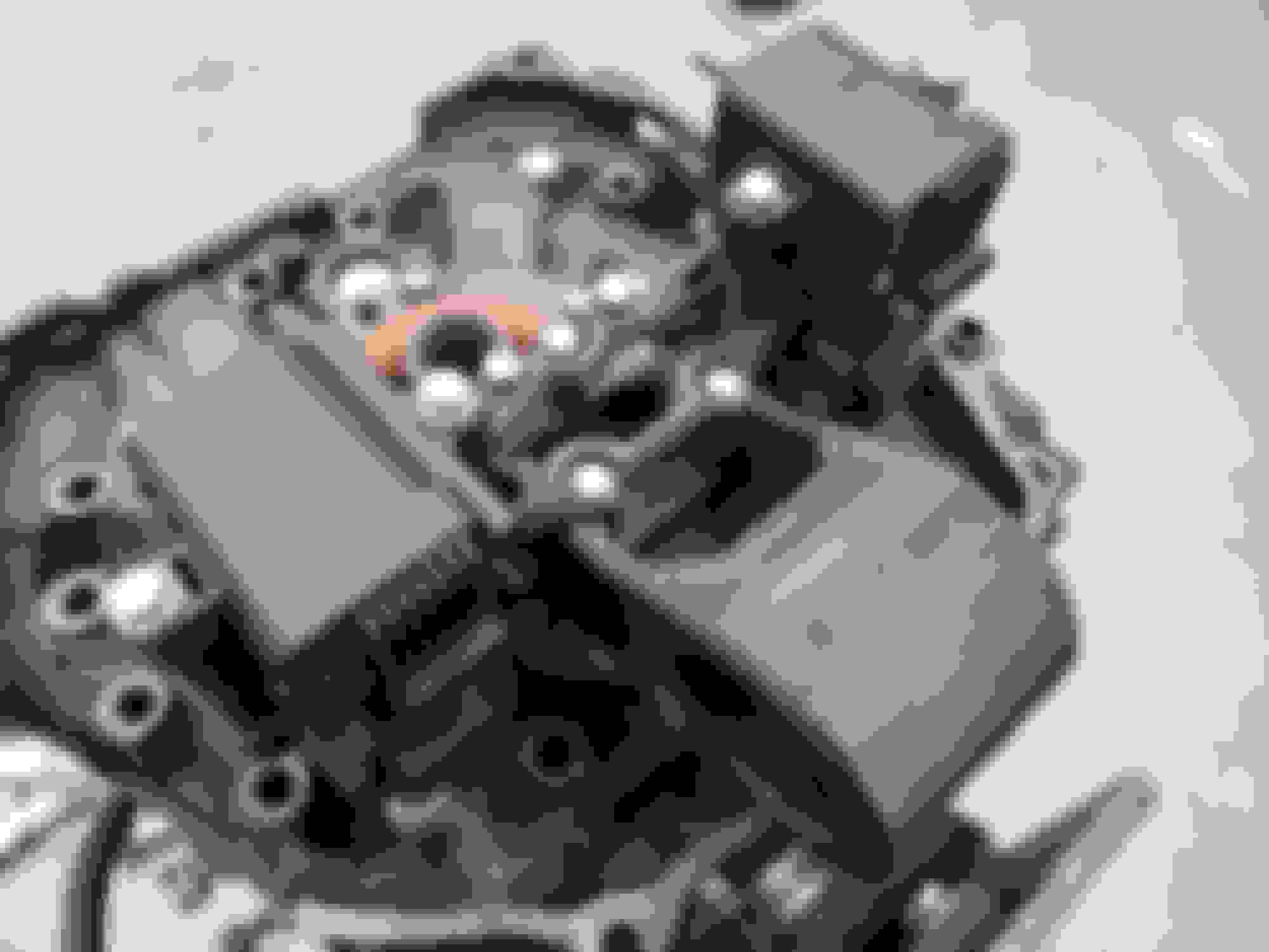
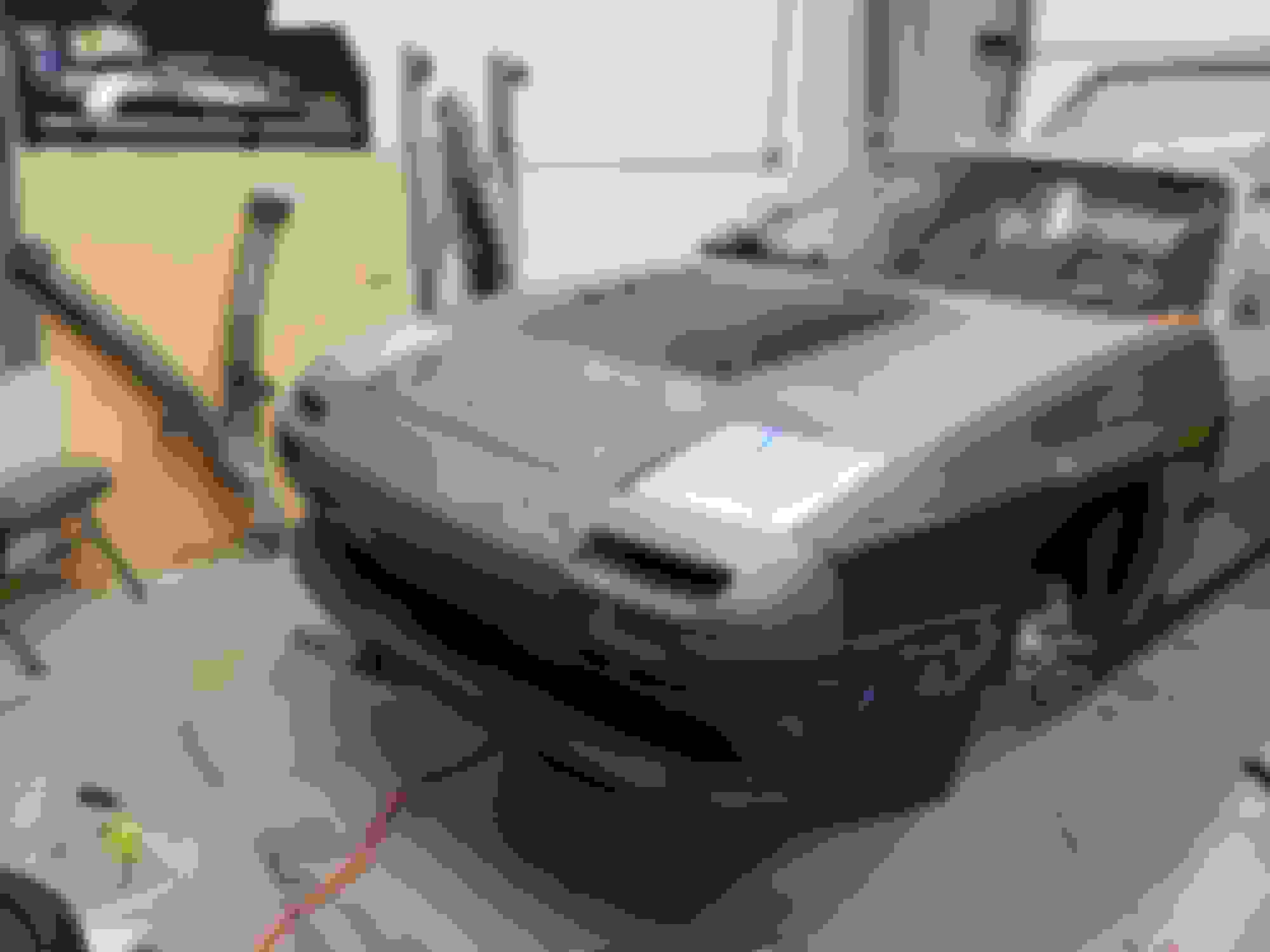
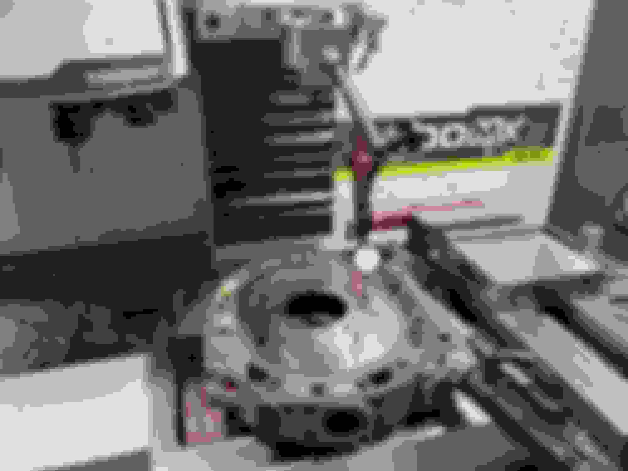
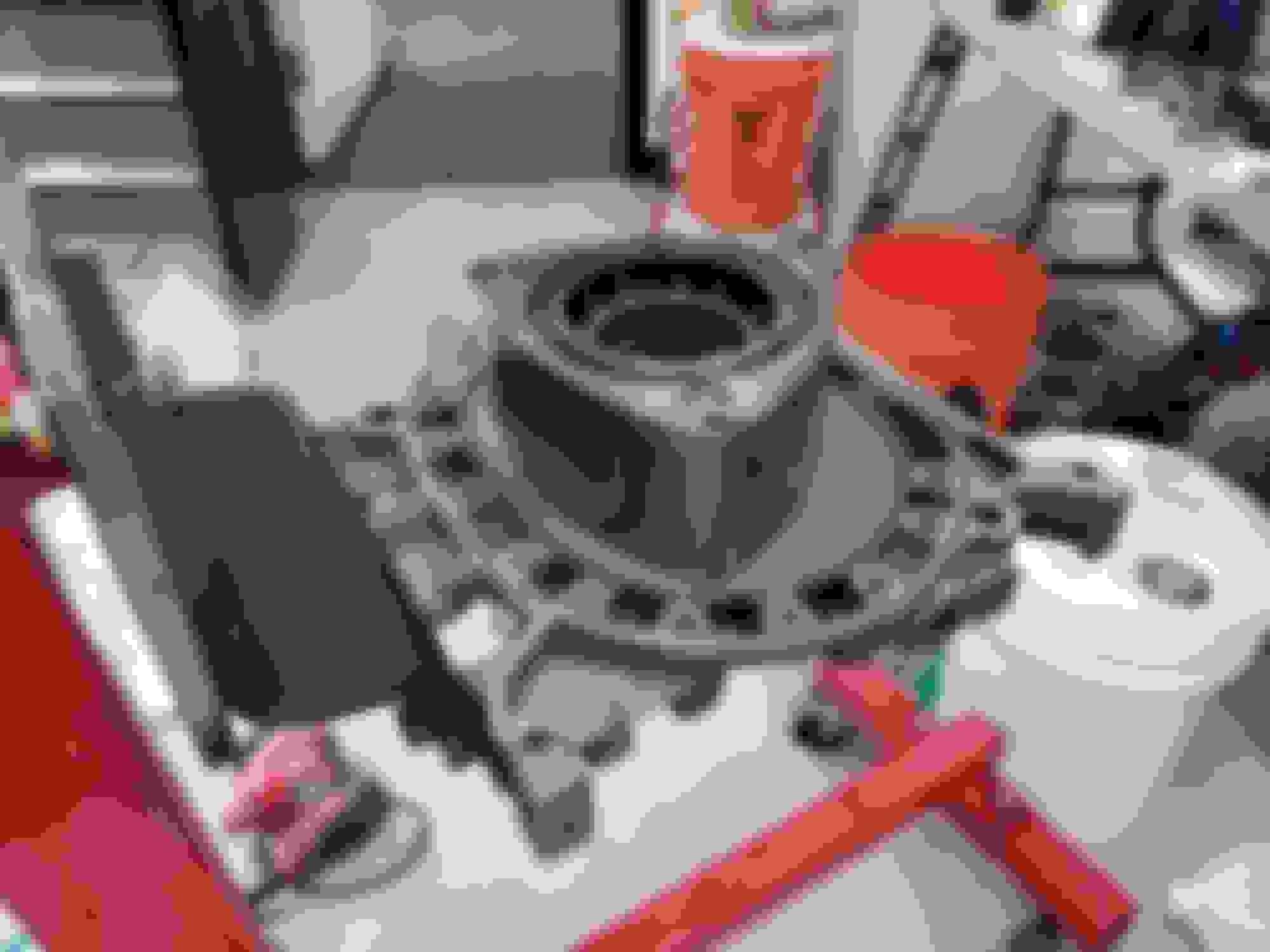
If there’s a silver lining to having multiple cooked engines hogging space in your garage, it’s got to be how easy it is to mock parts up. Got this setup on a stand:
Driver’s side engine mount finished printing, amazingly without any hiccups
And everything jigged up on the new mockup engine-
Uh
-and everything jigged up on the new mockup engine.
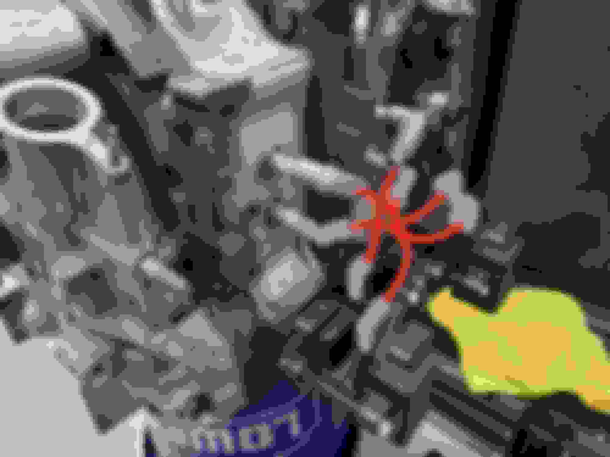
Preliminarily, I did this crap phone drawing of what I envision the plug leads to look like...
...but I'm starting to think this might be a bit infeasible if I stick to my original criteria that this coil bracket setup cannot interfere with the engine having AC. While I don’t plan on using the stock AC compressor due to a desire to switch to R134a, it seems like it’ll be a tight fit, whatever I put there.
Most compressors I've seen from the RX family and otherwise are a bit football proportioned with a badonkadonk that would stick out towards the back a bit past the mount studs. That would have the back of the compressor butted straight up against the outer forward coil's post. Most likely going to have to flip that coil 180 degrees, but for wider context, I'll work on a rough sketch for later today's update on how exactly I envision the packaging components in this particular region. There's also the RX8 compressor, which is pretty stumpy
Also I’m realizing this plug wire kit I had on hand is not exactly the kit I thought it was. Probably need to pick up some more of the 90 ends instead of whatever this horrific Britbonging is going on here.
Brought a pile of additional big ticket items to the shop for the mockup jig this morning so I'll update my findings later today.
since you can, you should set it up so either the spark plug wires are as far away from each other as you can get (and other conductive things)
OR
they all cross at 90 degree angles.
the search term is "inductive cross fire" but basically the 90 degree cross cancels the inductive pulse, and having them separate means the pulse isn't strong enough
"...So I have the coils situated right next to the spark plugs, bolted to the engine, but out of the way of everything else in a relatively underutilized space..."
...or my clown *** could have just entirely forgotten about where the steering shaft goes. I should just drag the entire car to my shop already.
I dug up this image from when I was still utterly delusional about fitting this giant remote dual filter assembly somewhere in this engine bay, so just ignore that. From this perspective, it seems like there's a chance in hell the coil bracket assembly still fits, so I'll have to investigate after work. This just crossed my mind after the caffeine kicked in.
There's also the oil cooler line but I'm reconfiguring the oil system in general completely clear of this area, so it doesn't matter
since you can, you should set it up so either the spark plug wires are as far away from each other as you can get (and other conductive things)
OR
they all cross at 90 degree angles.
the search term is "inductive cross fire" but basically the 90 degree cross cancels the inductive pulse, and having them separate means the pulse isn't strong enough
I'll see about trying this. Never heard of inductive cross fire, learn something new every day. Appreciate the tip
My crap sketch has the lines all converging towards the center iron so I could constrain them with a wire separator there (magically attached to thin air for now, might need to extend yet another bracket off the engine mount for that). But from what I've read about IGN-1As, they're feisty little coils so I should take separating the wires more seriously
even from your sketch it looks like you're pretty close, its like you could turn the coils so that the posts are on different sides
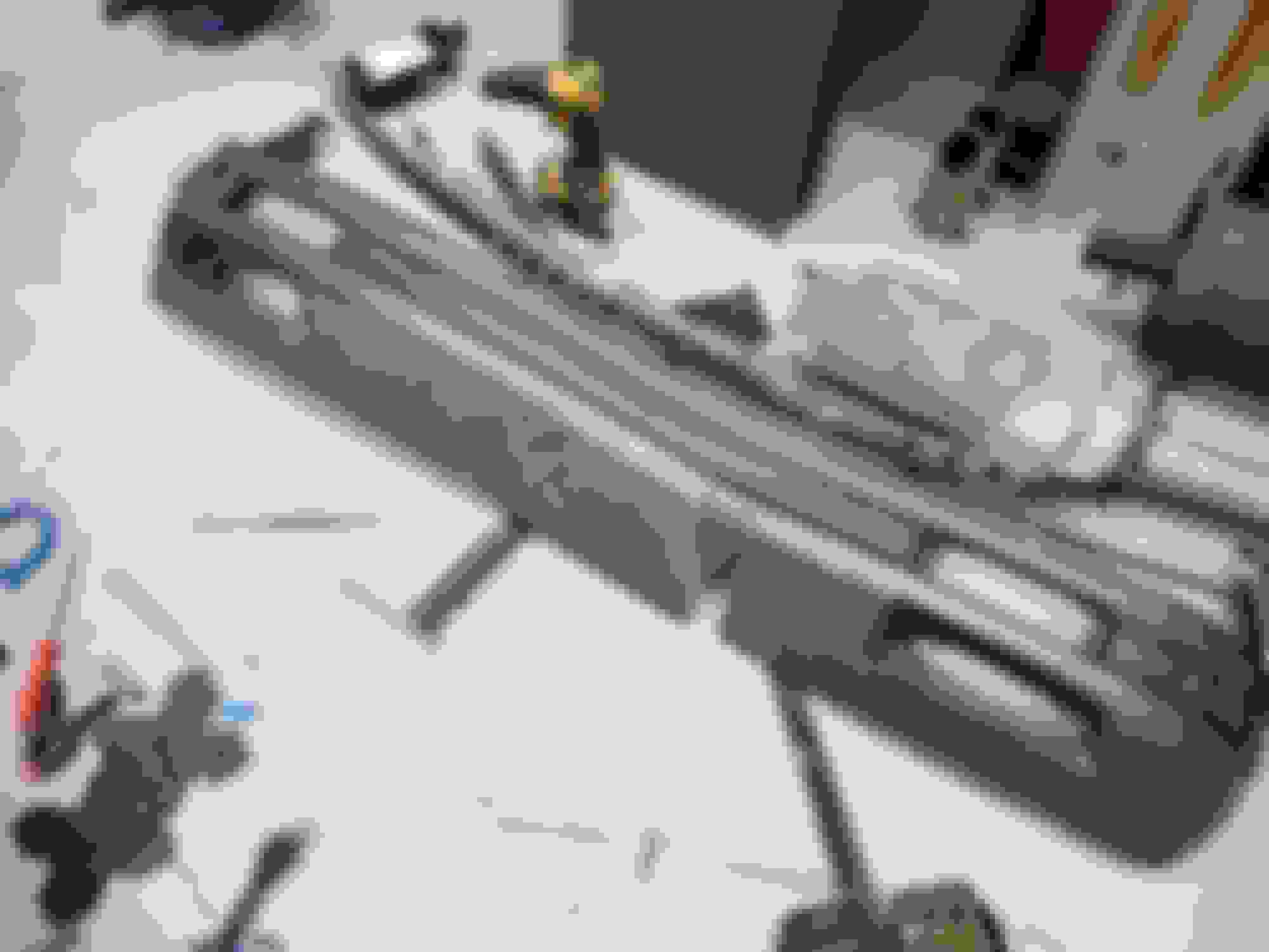
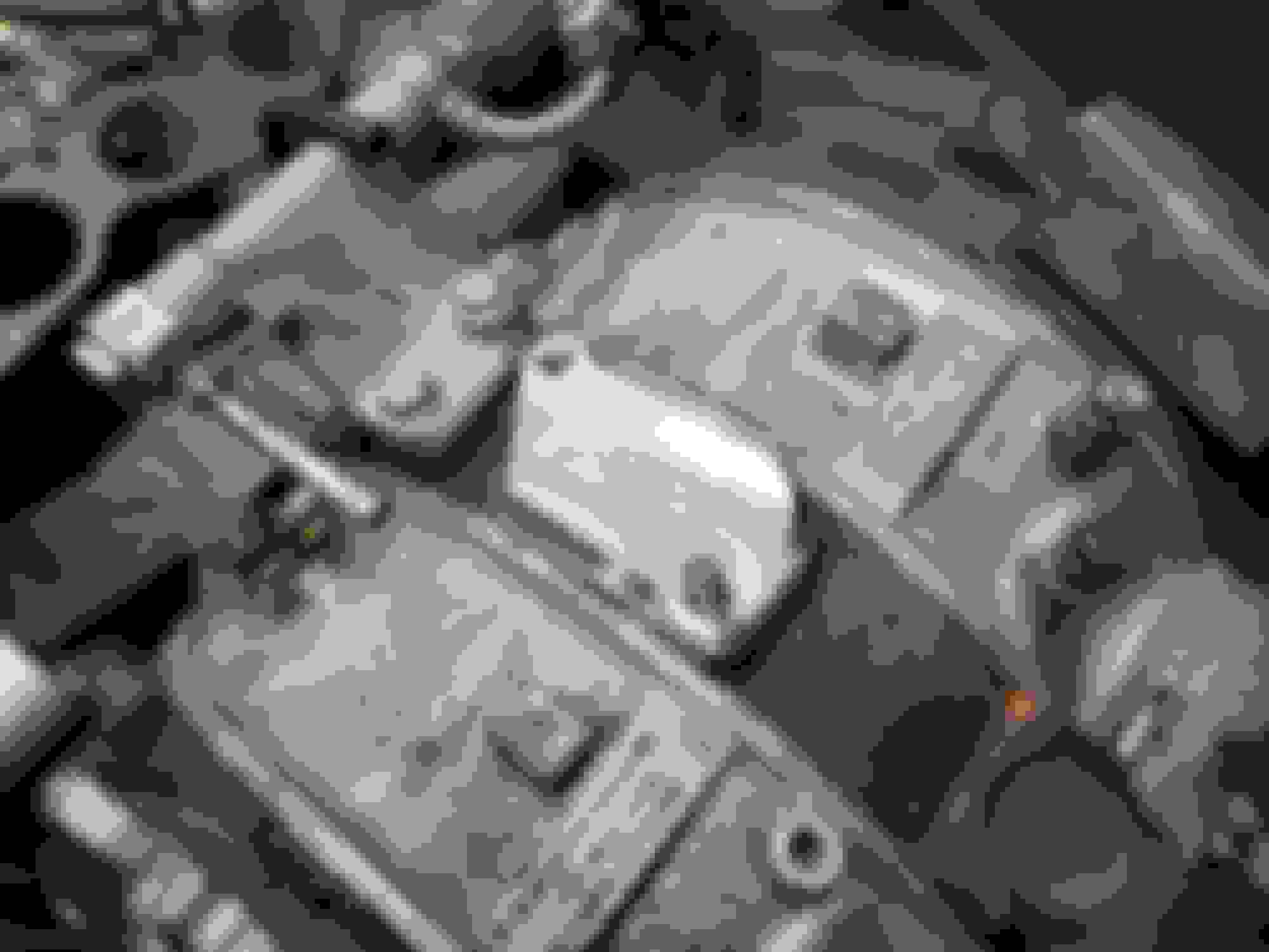
Slapped on the bits that I brought from home. Right now, it's S4 LIM, S5 UIM, FC (I forget if these are compressor specific, this one had a NipponDenso compressor bolted to it originally) A/C only bracket, FD compressor bolted in with only one bolt lol. Didn't do much else, yesterday was a certified Thursday type of beat where all my time was consumed by work despite barely getting anything done.
General observations:
-I thought I was being clever using an S4 LIM with an S5 UIM to reduce compatibility issues, but this far back stud is so off I don't think I could comfortably grind the landing pad out enough to get it to bolt up without windowing the runner. Might need to go about sourcing an S5 LIM (can't see why it wouldn't bolt to an S4 block)
-Rabbit hole reading about spark plug bolts with IGN-1As. Mine definitely don't reach the hex flats on the plugs... Same with reading into distance between post and the bracket it's bolted to. My design has barely any clearance. More relief needed or an insulator added if this bracket concept is still feasible. Forgot to bring it back home to check against the car
-If the bracket can be made to work by bringing the coils closer to the block, I have about 16mm because I forgot the center iron protrudes past the rotor housings by a fair distance
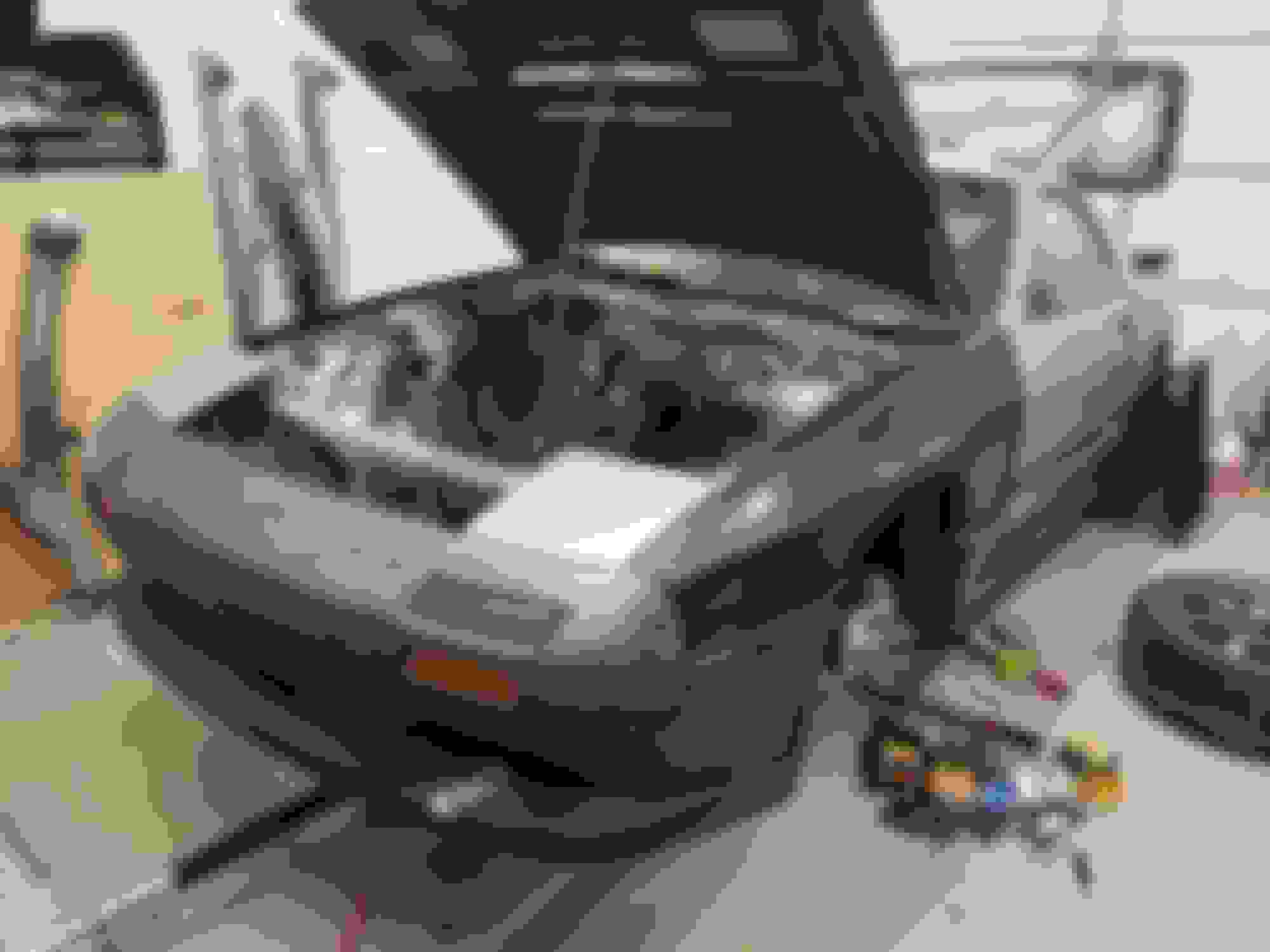
-It looked fine in CAD but the engine mount bracket is way too huge in real life. Pics included comparing it to stock. Need to shorten the bracket and probably size down the bushing. Right now, the bushing diameter is 55mm (>2") because that felt right, but that might have to be bumped down to like 40mm
-For reasons I'll explain later when I follow up my promise on that sketch, I might have been railroaded into using the RX8 AC compressor now that I'm looking at how parts are starting to fit together
-More shopping list: S5 BACV, plug boots or made-to-order wires. Make or buy: S5 secondary fuel rail, bracket to support intake manifold
we ran an S4 lower with S5 upper (or maybe it was the other way round?) and 4/5 bolts seems like it was good enough. i mean 4/5 i could have gotten to an easy A in school...
maybe you want the intake support bracket?
we ran an S4 lower with S5 upper (or maybe it was the other way round?) and 4/5 bolts seems like it was good enough. i mean 4/5 i could have gotten to an easy A in school...
maybe you want the intake support bracket?
If you ran it without that stud, I suppose it doesn't matter either way. But if you had, I would have assumed you went with S4 UIM on S5 LIM since you could slot out the flange on the UIM to access the threads in the UIM. Going the other way is a lot more problematic. I vaguely recall there was a time when people assumed the S4 UIM flowed better because smooth bends rather than taking Hemholtz resonance into the equation. Havent seriously investigated how hard it would be to get am S5 LIM, but if I cant, I could DEVCON/weld -> mill/drill/tap an extended ear on the LIM.
I'm an idiot, so I'm willing to go a long way to get the S5 UIM on the car, and clamped down appropriately to the LIM. I didn't elaborate previously, but I'd like to ultimately make a 6 port turbo out of this particular engine with a Cartech-esque setup, WAIC and everything. So positive manifold pressure is a consideration, and I'd like the bolts to all be there. The screaming obvious path of least resistance is to just use the damn S4 intake in its entirety, which I have the rats nest/manifold support bracket for, and BACV, and secondary rails, and I wouldnt need to ogre the OMP rod to work with the slight shift in location of the TB, etc. etc. Part of me hopes the S5 UIM makes the engine a smidge more responsive and quicker to get on boost - maybe it winds up making zero difference. But my dumb *** is gonna put it on the engine because I think S5 UIMs look better and because I can. I also have Maslow's 3000lbs hammer in the form of the CNC to make it fit. I will probably use it to make the intake support bracket at least. If you haven't already picked up on it, I keep making overcomplicated parts that do several things at once, so I'd probably incorporate a flex fuel sensor mount, wire harness strain relief mount point, boost solenoid mount, beer opener, and breathalyzer into the bracket
Costco linner/dunch right now, and this time I have the bracket in the car with me so I can finally go find out if I can go through with this coil bracket design
we definitely followed the S4 is better herd, not sure it was. we really didn't test it, we just read some stuff and put it on. if i did it now, i'd at least try to quantify a difference.
subsequently i had an S4 and S5 as DD's and the S4 being a coupe, and ~200lbs lighter, felt better in the idle-2000rpm range than the S5 did, although if you had the time to wait for it the S5 pulled harder at higher rpm.
the S4 peaked around 6500, S5 kept going to 7k+.
the S5 had more potential, not only does the intake work at a higher rpm, but the S4 used exhaust backpressure to open the ports, so you needed ~3psi or so, which it did with the stock exhaust. the S5 you don't need that backpressure, and you get a gain there too
I'd like to do a back-to-back test eventually, just don't have the spare funds and time to do so
Final say on the coil bracket is a firm no as-is. Steering shaft was indeed an issue, I wouldn't be able to get it to work with the AC/PS bracket (never paid attention, but maybe the AC only bracket moves the compressor up a little?), and I completely forgot there's studs in the bottom 2 threaded holes in the front iron, which my mock-up engine has removed for whatever reason. Moving the coils up and closer to the block might work, but it's hard to say if I could get it to package just right and then the ignition leads would probably suck to figure out.
Started getting some silly ideas where if I had to redesign the bracket and engine mount entirely, I might as well see if a COP setup with the IGN-1As was at all possible. Possibly with a giant bracket and the coils situated 90 perpendicular to the plugs, but then I'd need to sort out a boot and "wires"... Maybe I crimp ends to a spring and stuff it into a boot? That's what coils that were originally meant for COP applications do, so...
Either way, I think this really highlights the fact that I need to sort out a real test fit jig in the form of mock-up engine in the damn car, or a 3D scan of everything put together. 3D scan seemed like the low hanging fruit at the moment, so I took the dive with one of those 3D scan apps you can download onto your phone. The one I tried is called PolyCam, and I'm blown away with this kind of technology.
Only issue is trying to get this scan to be usable. I can open the file in Solidworks, but it's in mesh form, which I can't clean up, and I can't manipulate much. I'm not even sure on how to scale the thing appropriately yet. As is, if I can figure out scaling, I could drop parts into a 3D scan of the engine bay to get some approximate locating ideas, but not much else. I wouldn't feel too confident about trying to squeeze a part into a space the scan says will work until I can make the scan fairly accurate. Still investigating how to get a usable solid. Tried using the Scan to 3D add-in, but I can't even get it to open the file correctly. From the past couple hours of searching, it sounds like Solidworks broke the function in the specific service pack I'm using and then fixed it in the subsequent update, but I really don't want to beat my head against the wall more with this at this moment.
That being said, if I can sort out the workflow to getting usable models out of 3D scanning, I could conceivably start collecting scans, critical measurements (with hand tools, or by turning the Tormach and probe into a really crap "CMM"), get models of all the stuff I'm hoarding, and then sell off everything that's just on hand for reverse engineering. I know people want this AC only bracket I have, intake manifolds, water pump housings, etc. etc. which I likely won't use or will replace with versions I make and just need dimensions from. That way I can liquidate now and stop whining about not having the funds to continue the build. And for my dumb compulsions for stuffing parts from the wrong car into RX7s, I can go to junkyards and start getting scans of stuff from cars there. I nearly dropped everything I planned to do today to go to the junkyard and get scans of the RX8's alternator and AC compressor, but not being able to figure out how to turn these scans into usable models has derailed that.
I should probably invest in a proper 3D scanner eventually
I have fusion 360 and I can make STL meshes into solids, if you want I can make that into a solid and export it to you as a file you can edit.
Appreciate the offer. I have access to a copy of Fusion 360 and just did a bit of a deep dive on how to go about doing it. I'd like to learn and become proficient at doing it myself, since I have a pretty large collection of parts I'd like to make digital models of
Not really much to report from the past couple days, just getting caught up with work and investigating the 3D scan pipeline. My father and I share a gen 1 Kinect which may come in handy, I just need to figure out who the hell has it and where it went.
For better or for worse, I now have the option to not finish the car and still bring it to Sevenstock. Likely going to get an open deck car hauler trailer soon. I don't know if my pride could handle bringing a non-functional RX7 to Sevenstock, but I suppose it's better than curling up in a ball and staying at home for the weekend. Might as well take the **** out of it and rename this thread into SEMA RX7 BUILD 2023. I can at least get as far as making the exterior/interior look OK, machine some pretty doodads, and throw a loose driveshaft in the back hatch; call it a day.
This week is shaping up to be a bit ugly with work, so I don't believe I'll be able to provide daily updates with any substance. But the goal is to have shop affairs sorted and the place cleaned up so I can get her loaded up on a trailer and brought over to the shop this weekend. In the meanwhile, I'll update if anything of interest happens, but I'll in all likelihood be checking in after a week
So for complicated reasons, I wasn't able to arrange for the car to be on a trailer in a reasonable time via cashing in favors, so less than a week from the event, I just said "screw it" and rented a uhaul.
In the midst of this, I was crunching on some customer prototyping work, so the actual time I got to work on the car wound up only starting from the Wednesday immediately prior to Sevenstock. For ***** and giggles, I decided to register the car in its embarrassing state of disassembly for the car display at Sevenstock. Just some motivation to at least attempt to get it put together (Wednesday night was the deadline to sign up for the car display, so I figured if I was accepted, I clearly wasn't denying anyone a spot if I ended up a no-show).
A bit of caffeine delusion and an email response saying my heap got accepted into the show got me thinking I might actually put it together in a running, driving state in time, so I started crunching really hard. I was still under the belief that if I was going to go, my fallback was to resort to the SEMA plan of ricing the car to semi-presentable state even if I couldn't put the engine together in time. So I started there.
First order of business was to deliberately swap out the front bumper for one that was even crappier than the one currently on the car and slice it up to fit the half bumper. This one I nicked off the full size mockup car in the backyard after I noticed the bumper was already cracked above the molding.
Then to measure, drill, and rivet in the rivnuts. These were secured to the urethane bumper and the front half of the fenders, so I wanted some sort of backing washer to prevent pull through. Up till now, I thought there was zero reason to be buying M7 hardware of any description, and yet here I am, finding out they are a perfect fit to slip over an M5 rivnut.
Then to undo the work and deliberately make the bumper even worse. This bumper was already in rough shape, but man this didn't feel good for someone with mechanical sympathy. I tossed, dragged, and ground the thing into the asphalt before taking a saw to rip a new "crack" into it. Then re-undid the undo with zip tie stitching. I promise this will eventually make some sense
Oh right, at some point I did install the hood pins. I wanted them in a specific location that was a bit further back up the hood, but it would have been floating above zero sheetmetal and I didn't have the time to fabricate something, so I opted to stick them where a pair of hood stops used to be. Had a not-so-fun experience trying to rivnut the top pieces in place with tiny M3 rivnuts, only for the crap Amazon rivnut mandrels I was using to strip out the threads before deforming the rivet because they were undersized. My bunk *** workaround was to "crimp" the rivnuts around the mandrel into a faintly egg shape so it had more purchase on the threads, rivet them in place, then chase them out with a tap.
Then the undiagnosed ADHD kicked in and I wound up driving nearly 3 total hours to pick up some S5 NA and RX8 components that were things I wanted to mess with in the future, but likely weren't going to be something I could use on the car before Sevenstock. In total, I grabbed:
RX8 alternator
RX8 AC compressor
S5 air intake assembly with MAF and everything
S5 BACV
S5 NA LIM
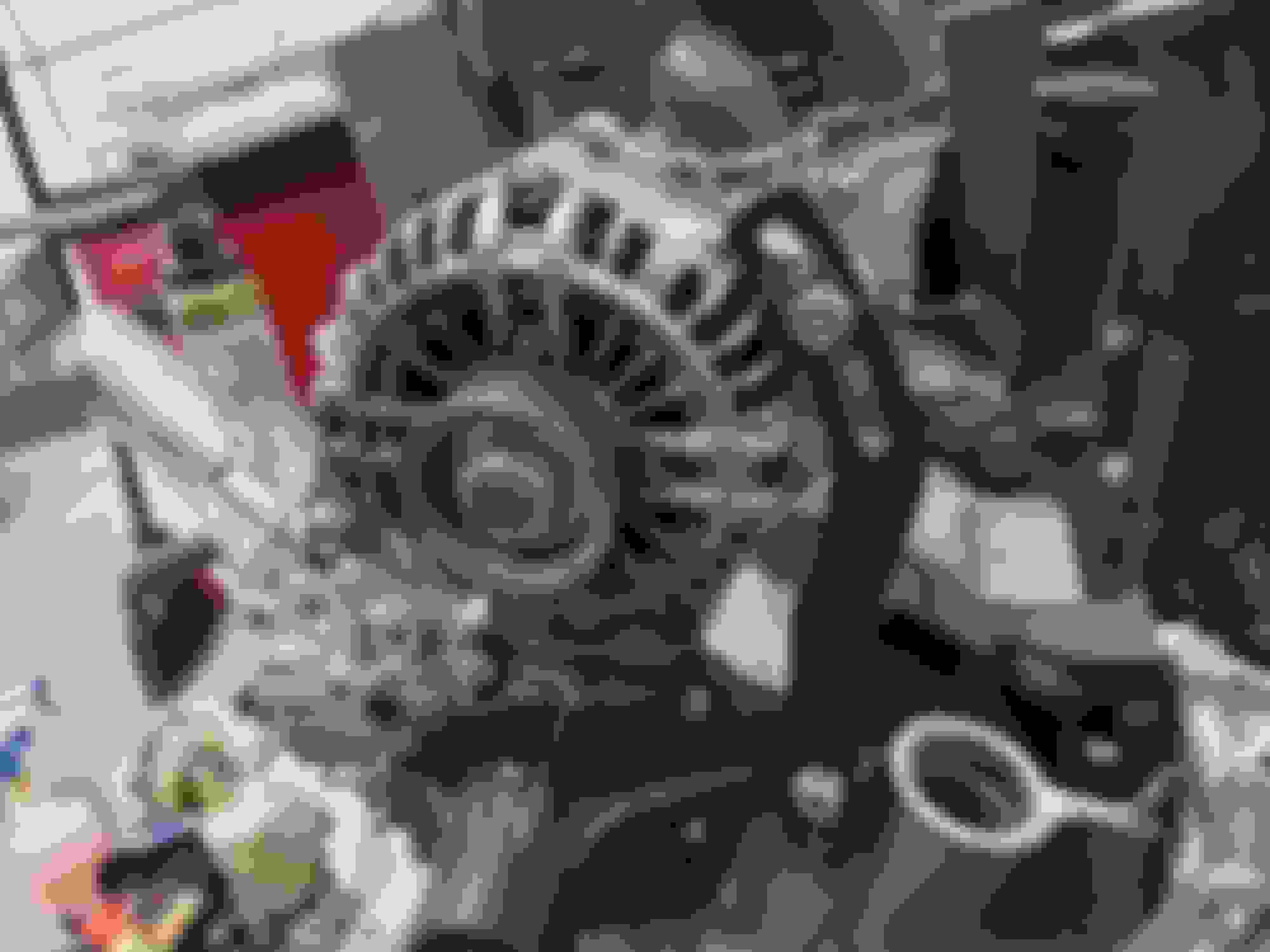
Instead of shoving them in the back of the shop and not messing with them like someone that has other priorities and a giant looming deadline, I went to see how the RX8 components would fit up on an FC block. SUSPICIOUSLY well, I'll tell you hwat
This is the alternator fitting up with the stock FC spacer and tensioning bracket, and all 4 bolts on the AC compressor matching the pattern for the FC compressor bracket. I'm sure this is documented elsewhere on this forum, but for me discovering this for the first time, it really felt like Mazda was just trolling at this point. The only issues were the alternator post positioning, but I feel like with more investigating, I should be able to rotate it. That and I haven't spent any time considering belt/pulley positioning
Anyways, at some point, the caffeine delusions REALLY kicked in and I started convincing myself that I could totally rebuild an engine for the first time and I had everything necessary to make it work. All the S4 NA ancillaries were still left assembled in as large of assemblies as I could leave them as, I had an Atkins rebuild kit I wasn't tore up about wasting on a garbage engine, I had pre-made gaskets for everything this time around so I didn't need to mess around with cutting my own gaskets, and while the engine internals weren't in that nice of shape, I had all the parts and it was all in specification. I ended up using the Tormach as an oversized jig to check step wear on all the NA center irons I had and found one in my pile that wasn't too egregious at ~.002" for the side seal step wear. I say that but it was still a victim of water damage and not terribly nice to look at. None of the pitting really catches a finger, but you still know its there
Aggressive clean schedule meant I had everything prepared in roughly 16 hours. Slaughtered my back in the process. Also needed to take a page out of RotaryEvolution's book and skim some JB weld over some mild corrosion pitting on the faces of the rotor housings. These were out of my black T2 and the closest thing I had to usable rotor housings. That engine ran great, mind you, but it did start to have some mild chrome flaking and one of the coolant seal walls on the rear iron immediately departed the building the instant I took the engine apart. Previous owner clearly didn't pay any attention to coolant maintenance. The corrosion pitting on the rotor housing was kind of to be expected
In the spirit of not knowing what the hell I was doing, I did a bunch of fervent googling, reading, and came up with my own "refurbishment" plan for the iron surfaces by using a mish-mash of disjointed advice. It looked roughly like this:
Preliminary clean scraping out the coolant seal grooves with small flathead screwdrivers and taking green roloc pads to the gasket surfaces. I forgot that while I had cleaned my original engine and its components of the original Mazda gaskets, I still had to do the irons, which came from facebook marketplace sellers, and they all still had the original gaskets Mazda made from Satan's underwear
4.5" palm sander, medium speed, wet sand with 180 grit for no more than 10 seconds per surface. This was supposed to be to add swirling marks and to deglaze the surface per Lynn E Hannover's writings, but I think I made the mistake of using this product called Diablo Sandnet, which doesn't seem to have a proper aluminum oxide abrasive and was probably meant for woodworking. It pretty much ended up being an aggressive cleaning for the surface
Generous application of valve grinding compound, lap irons together in a figure 8. I would lap either the front or back iron with one face of the center iron for roughly 60-75 motions, flip the center iron to the opposite side, and finish lapping. Idea was to get 3 separate surfaces to interact and prevent any 2 surfaces from marrying to each other. It would usually get to approximately the same number of motions on the opposite face before it really felt like the irons were "sucking down" onto each other. I don't quite remember what exactly this is, I think its a combination of the compound's abrasive particles getting worn out, the compound being so full of abraded material, and the surfaces getting flat enough relative to each other to stick from increased surface tension. I didn't spend more than a total of 45 minutes on this, so judging by what other people have said, I did a really hasty job of this and pretty much only knocked down some high spots
Powerwashing the bejesus out of the irons to prevent the grinding compound from hanging around
This mixing and matching of advice probably wasn't ideal, and admittedly after that, I didn't get a totally satisfactory surface. There was evidently a fair bit of glazing left, and the matte surfaces were a bit patchy-looking, but I also didn't want to push my luck with accidentally burning through the nitriding, so I left them as is
Now for the thing that really killed this harebrained scheme to go to Sevenstock: the damn freeze plugs. I had already noticed the front iron had one plug that had rusted a hole through it and I wrestled that one out with a lot of cursing and more back pain. These little bastards were invasively rusted into place and really were a bear to get out
But it was only until after I had powerwashed the irons that I noticed the rear irons had 2 very suspect plugs as well. My suspicions were confirmed when poking at one of them with a screwdriver, I smashed through it with less force than it takes to poke a hole through printer paper. These little ***** were somehow even worse than the front iron plug. I consistently blew out the center of the plug with 2 of the mandrel sizes, and it was only with the 3rd and largest mandrel I had, the iron situated on a welding table, with me pulling through one of the slots, and a second weight pilfered from another slidehammer that I was able to knock these 2 loose. The rust flakes that fell out were astonishing
This was pretty much the straw that broke the camel's back. While I did get started on the engine rebuild proper, I had wasted multiple hours on the freeze plugs and my patience was extremely thin. I pretty much threw in the towel when I started struggling with the apex seal springs not seating correctly because I had goofed the assembly process.
There were only a couple hours from when I gave up on the engine rebuild to when I had to be on the road to make it to Sevenstock, and the engine rebuild had absorbed so much of my attention I completely forgot to actually finish the rest of the exterior and interior. That confirmed I wasn't making it there with the car, and honestly, at the level of sleep deprivation I was at, I wasn't making it there at all, car or not lol. Pretty much a textbook case of **** poor prioritization of tasks and time management. Oh well, lesson learned. At least I made leaps and bounds in progress on the car
Something that was happening in the background of all this was my friend making a batch of vinyl diecuts for my "livery" in one of the office rooms. While he was far from completing the full set required, he got pretty close. As a consolation prize, we applied some of the vinyl (and I fucked up the placement of almost all of them), tossed the wing on to get pictures and think about "what-if" before going the hell to bed
Finally, I can explain that, yes, this car IS supposed to look like a complete trashfire. The design is lifted from Need for Speed: Prostreet, which is a bit of a glamorized game revolving around grassroots circuit racing (glamorized in the sense that you aren't spending half your budget on brake fluid and pads). The car that features in the opening cinematic is this beat up dark green FD that oozes track weapon energy and has all the battle scars to suit. It stuck with me as a kid up till now. So when I was looking for excuses not to having to repaint the RX7 after the complete circus that was respraying the Civic, I almost immediately thought of it. It's a bit silly that I'm doing this high of a level of ricing, giving this car battle scars it doesn't actually have and generally making it look like it gets raced when it never has, but **** it, it looks ridiculous and I love it
The day immediately following, my body hadn't actually realized it was supposed to be sore, so I squeezed in another day of messing with vinyl to get closer to completing the livery. There's still a few smaller things to take care of, but I ran out of both black and white vinyl, and after chatting with my friend that was helping me with the vinyl in the first place, we decided some of these needed to be spray paint stencils anyways. But even in its incomplete state, it looks mostly there
So there you have it. Made a complete hash of my plans, got nowhere near where I wanted, but did make a hell of a lot more progress than I had for the past few months. Maybe next year. I do want to try to get this car put together and running in the next 2 weeks, this time without cutting a bunch of corners, just to prove to myself that it was remotely feasible to make it to Sevenstock had I not waited on a tow and maybe didn't **** up prioritizing tasks.
Also everything still hurts from the crunch almost a week after. Maybe I'm getting old. I've been listening to medieval history podcasts and being drawn and quartered sounds borderline cathartic with how awful my lower back feels.
Switched gears back to making shiny stuff on the mill. Little baby steps but excited by the progress
Quirk blurbs on the above:
-EGR block offs were inspired by something I designed for a customer, and after I made my customer's order, I looked at the EGR block off on my car and thought "wow that looks shoddy by comparison, let's see what I can do to remedy that"
-Transmission mounts are very solid and very stupid (I'm sure I'll get sick of them being on my car within a week) but after hearing forever about how the ones people sell are always thru bolt designs not accounting for the offset the factory mounts have on the studs, I decided I'd make my own. They're just a stepping stone - now that the mounts are 100% rigid, I should be able to get good 3D scan data of the crossmember assembly for what I actually want to make
-Did I mention I got a 3D scanner?
-Vulcan Autoworks was a name I came up with years ago for an unrelated venture and incorporated an LLC of back in like ...2017? (yes way back in college lol). I've since decided to repurpose it as an extension to the machine shop to sell any car parts I come up with. I settled on the name after googling it and not seeing anything come back, without ******* realizing I needed to just look in this forum and use an "x". No affiliation to Vulcan Autoworx. Bit embarrassing. For any mods reading this, I'll make sure to keep the thread strictly about this heap, I just cant do anything about my terminal illness of wanting to replace half this car with billet parts that might wind up for sale later
-I also still havent forgotten my promise to put all that electrical connector data up on a website - hopefully it's kosher that it's getting hosted on the tech section of the Vulcan site
Anyways, hopefully when things calm down, I'll have another crack at putting together the short block. On the to-do list is to make some shiny tools on the mill to help with that, so it _____should_____ go a lot smoother. (Should) (maybe) (probably not)
I am rotting in bed after catching some sort of flu (in summer??? chills in 110*F weather????) so I will try to piece together whatever happened since the last update through the brainfog using whatever pictures I have on my phone
So the biggest development is that we are machine-less again. Very bizarre arrangement where a machine shop is operating with no machines, but here we are. An opportunity came up to pass the Tormach along and well, my business partner jumped on the opportunity to dust his hands of it. I kind of wish he had the patience to wait until we got machines in to replace it, but uhhhh... yeah. I also can't blame him. To sum up a multitude of complaints, the machine is built around the idea of a home hobbyist or home business operating it, and is pennypinched to do nothing more than that. In our new circumstances, the machine was a total fish out of water. Our new shop has 16ft tall ceilings, 3 phase electricity, and a 10x10 rollup door to get equipment (and a forklift) in and out of. Everything that made that machine initially attractive no longer mattered and with our work shifting more towards steels, cast irons, and tool steels, the tiny spindle and wet noodle casting were doing us no favors.
Here's a couple anecdotes to illustrate how handicapped we felt by this machine. In anticipation of possibly making our own fixturing plate for its bed, we wanted to know how large of a flycutter we could potentially put in the machine. We were envisioning something like a 6" diameter UFO-on-a-stick type of flycutter with a single cutting insert counterbalanced with a weight. I've seen guys with manual Bridgeports fashion these types of flycutters with cutting diameters of 12"+ so 6" felt reasonable. We contacted Tormach's support to try and find out a) how large of a flycutter we could run and b) what the maximum tool weight was for the spindle. Support was sticky about giving us a real answer, and the best we got was "we don't recommend cutting diameters larger than the tool we sell (a flycutter adjustable out to 3") and don't recommend going over 4 lbs for tool weight". That shot the 6" flycutter idea down pretty quick and the 4lbs limit... Well. We were already nearly afoul of that with just our 1/2" drill chucks and 2.5" face mills.
The other anecdote I can give you is how one of the last jobs that machine ran for us turned into a total circus. A customer needed a rush job done to open up a hole on a cast iron housing. This piece was at the ABSOLUTE limit of what this machine would fit. I had to handload the tool after the housing was strapped into place because at max Z height, the shortest tool holder/cutter arrangement we had on hand did not clear the top of the part. It nearly smashed the part into the tool changer every time it interpolated around the hole, so we had to re-setup the part to do the other hole because there was no doing both at the same time. And it was a back-breaking pain in the *** to get the part in and out of the machine because the doors don't curl over the top like most real production CNCs do to allow loading things via gantry, so we used 3 guys (I had to be the one to crawl into the machine), a cart, and a 3 foot bit of 4x4 lumber. We ended up spending more time finagling the part than actually machining it.
I hope this sort of illustrates our state of mind when we jumped at getting rid of the machine before we could even replace it. There's no justifying being a machine-less machine shop, that's just irredeemably stupid. But we're looking to resolve that relatively soon with new (to us anyhow) machinery. Still ironing out the financials. But if we secure the machines we have our sights on, we will be jumping from the 2HP and 1,600lbs total weight of the Tormach to a whopping 30HP and 17,000lbs total weight for the replacement vertical. The trade off is that the machines will be 20+ years old, but we can live with that. Way in the beginning, when we first started this whole machine shop business, we were repeatedly told that there's no stupid electronic gizmos or trick features that can replace good, solid cast iron, and we are hard course correcting to that.
Technically I could be working to get the lathe operational (we sent out the main control unit for repair and it came back, fired up, but is spitting a bunch of error codes back at us, so I think I screwed up inputting the parameters by hand, and I'm stumbling my *** through figuring out how to talk to it over serial), but we have nothing lined up for it even if it did work. (I do love the amber screen and the noises it makes though)
Anyways. That was a huge tangent about everything not-RX7 to explain why I do have time to work on the RX7 suddenly. New priority is to boot the car from the shop because there will be no space to have a car and these new machines in the shop at the same time, and I'm not prioritizing the car being there over machinery essential to the business that pays the shop rent. Between then and when the machines arrive, I'd like to at least attempt getting the car to drive itself out of the shop, rather than have to rent another trailer to haul it around for the 7th, 8th, I don't know how many times I've towed it without an engine now. So while I wanted to machine a bunch of nice things to go on the car, that will have to come later.
So, step 1 to getting your engine-less car to run and drive is... paint the dashboard
Yeah I still haven't figured out how to prioritize ****
To make a long story short, I wasted way too long trying to get my hands on blue power window doorcards and eventually gave up and decided to match my interior to the back doorcards I already have. I didn't realize it until after I completely painted the dashboard, but I accidentally bought the gloss black spray vinyl instead of the matte black. It's not a great match to anything else in the interior, but, I suppose it's relatively period correct to the overly slick, greasy looking black plastic interiors of the 80s and 90s. With a bit of shiny interior protectant, most of the unpainted plastics will probably look close enough to the sprayed plastics
A big part of why I wanted to spray vinyl all the interior pieces was to hide just how bad the interior pieces actually are. While I was a huge fan of the interior being blue, there's no spray vinyl paint match for this particular shade of blue, and I refuse to go through that whole house paint debacle again. I did most of the interior the first time, but left the A and B pillar trims alone. Now that they're out, you can see just how atrocious the fading was.
The spray vinyl also gave me the opportunity to hide just how many repairs I needed to make to these stupid trim pieces. I am not sure if you can feel my exasperation through the camera lens at having repaired a snap in this A pillar trim only for it to snap again.
After all the interior pieces got dressed down in black, it was time to put the 3D printer to work. I had mostly already finished designing the radio/gauge holder insert for the center fascia, and just needed to tweak some dimensions and add a bracket. And for the center console switch panel, I took @need-a-t2 's model from this thread https://www.rx7club.com/2nd-generati...hings-1157452/ and modified it to take a set of toggle switches. Appreciate you all making these models open-source. I don't really see anyone wanting my specific setup for the radio/gauge arrangement (it's pretty obtuse, I don't recommend it), but I can post up the file if anyone wants it.
I was using this mystery meat PLA that came with some junk I inherited from a friend, and it simply refused to behave no matter the calibrations I tried. I have mostly been wasting it on fit check pieces and finally ran out of the garbage doing these 2 pieces. I switched back to my usual stuff (SunLu PLA+) and the difference is night and day.
I gave them a bit of paint (I found some leftover matte black vinyl spray from doing the Civic's interior) and the results aren't half bad for temporary arrangements until I can brave ABS or nylon (or go completely nuclear and machine them from Delrin or Aluminum).
Last task for the printer (for now), was a 3/16" tubing straightener. The design is downloadable here https://www.thingiverse.com/thing:4754659. Super neat arrangement, and dirt cheap, especially if you have a bunch of these 608-2RS bearings lying around. You just need the M8 flatheads, which admittedly were specially order for me. I am going to need it for the brake hardlines later on.
Some more side jobs - I scavenged a passenger seat rail to put on the gray T2 seat since the previous one was destroyed during that spinning nut incident previously. Used a carpet extractor to clean the seats as best as I could and really cleaned/lubricated the rails as best as I could. A small warning, it's a pretty freaking messy job if your rails were as gross as mine. I made sure to clean them detached from the seat to ensure the silicone lube River Thames didn't stain the seat fabric.
And then I installed a replacement side mirror glass for the passenger side as well. It had fallen off previously, so I had JB welded it back on, but that didn't seem to play nice and the mirror glass shattered at some point. From doing some research, you really want a specific type of silicone adhesive to do this job which grips glass well and remains a little bit flexible, but then I found some guys on a Corvette forum saying black RTV works well and I decided that was good enough for me. I had an extra tube of the gray stuff, which I know holds like an MF compared to the black RTV, and went to town. My only complaint with how this went was that the gray RTV's cure times definitely don't assume it to be structural and not sandwiched between 2 pieces bolted together. Instead of the 24 hour cure time listed on the tube, I think it took about 60 hours for me of the mirror cooking in a 95*F room before the RTV was solidified enough I trusted it to hold with the mirror turned upside down.
To finish out the interior renovations, I extracted the roof upholstery and sunroof upholstery... with the sunroof still attached. I don't exactly have a replacement panel and all the clips that usually get destroyed, so I intended on dyeing the fabric with everything in place. In removing the sunroof, I finally figured out what was wrong with the sunroof mechanism.
It had always done this stupid thing where only the front of the sunroof popped up like a really idiotic looking roof scoop, so I always kept it shut and ignored it. Looking closer, I realized the tabs that normally control the attitude of the front of the sunroof had snapped, resulting in the sunroof angle not being controlled, the back catching the edge of the roof, and the sunroof not being able to move backwards. I had scavenged a sunroof assembly off that red parts car and managed to put it to use here, as it was not broken in this respect. Unfortunately, those tabs were integral to the bracket that attaches to the sunroof panel, which meant the sunroof needed complete disassembly. (Side note - my sunroof, despite the broken tabs, was in shockingly nice condition. I wonder if it was replaced at some point)
Satisfied with the sunroof being disassembled to the point of maximum shop mess, my undiagnosed ADHD moved onto the upholstery. I attempted to vacuum it, but the fabric really, really hated even being looked at. It tore absurdly easily, so I pretty quickly resolved myself to just covering over the nastiness with fresh fabric.
The reupholstering job was total amateur hour, but I think most of my fuckups will be invisible once the whole shebang is shoved back into the car. Could be worse for $8 of fabric
If the order in which I tackle things seems really schizophrenic, the method to the madness was attempting to bang out everything that had a lead/cure time of some sort, such as adhesive drying, paint curing, and the next point of concern, RTV. We all know how prone to leaking these oil pans are if you don't take every precaution, and one of those is ensuring the RTV gets the full 24 hours to cure before anything liquid touches it. So naturally the engine rebuild comes next.
First up was redoing all the engine rebuild preparations. I had kicked everything to a corner to collect dust, and collect dust it did. I re-cleaned all the parts, ripped out old seals, and recleaned things again because I really, really rushed things way too badly during the last sevenstock spergfest. On closer inspection, I didn't really clean out the side housing o-ring grooves nearly enough, and I was placing way too much trust in the awful corrosion to the water crossover passage normally used for the turbo water feed. I ended up tapping them for 1/2" NPT (slightly crookedly, oops) and you can see from how malformed the threads are in some spots by the swiss cheese corrosion.
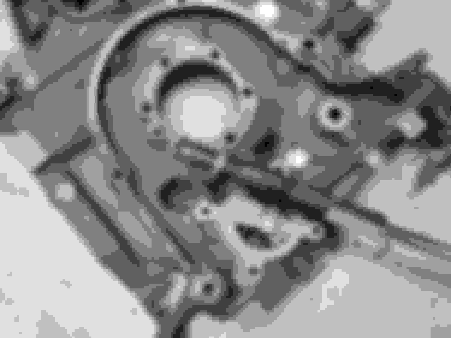
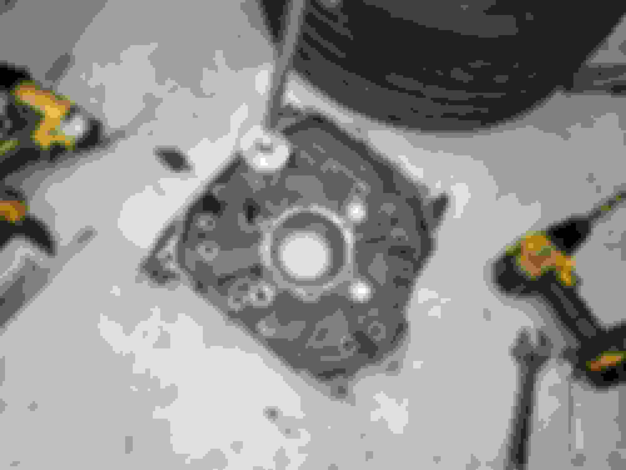
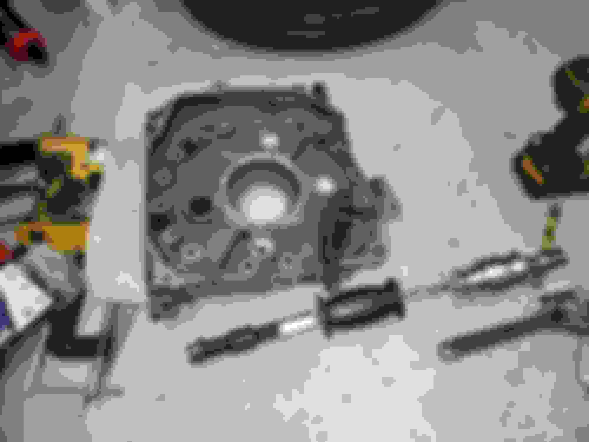
More preps, round 2 of the damn freeze plugs. If you can, for the love of god, knock them out with a punch from behind. It's a thousand times easier. When you can't, you're going to have to go with a slidehammer to extract them and it's ALWAYS a fight. Here's an image of one of the freeze plugs I initially left alone, the amount of rust buildup behind all the freeze plugs was pretty consistently this bad.
The next several hours were just a back and forth of cleaning parts, laying them out, looking to ensure I had everything, realizing something was missing, going on a wild goose chase, finding it, looking over the table again, realizing something else was missing, and repeating the headless chicken scramble for hours.
Once I was happy that everything was ready and available, I picked away at all the miscellaneous busy work I could do before stressing myself out with the time crunch of RTV out in the air. Main seals, stat gears, threaded studs, oil filter pedestal, o-rings, NPT plugs, etc. etc.
Man I forgot how much I lowered my standards with the center iron.... lmao
I finished up preps by fitting the corner seals, side seals, and rotor oil seals to each rotor, followed by recoating every hard seal in that Lucas assembly lube that has enough surface tension to stick a frying pan to the wall.
Finally, there was no avoiding it. The RTV had to come out, and the keg was getting stacked. This time around, I had my laptop with the FSM handy and, armed with a new technique for sliding the apex seals and springs in place, was able to make steady progress and stack the engine in short order.
I kind of made a hash of getting those freeze plugs into the front iron, but I got my **** together later on with the rear iron plugs and... I think these will hold. Hopefully. I added black RTV so.... (you have my permission to give the fattest "I told you so" the instant this thing milkshakes its oil/coolant)
Now, the endplay. This was simultaneously a total disco and a relative breeze. First attempt, endplay was a whopping .0075". HOSED. The maximum for a fresh rebuild is something like .0028". I've taken apart like 5 different S4 engines, so I had plenty of front stack parts to work with. Unfortunately, all of my damn endplay spacers were X or V spacers, which meant I could do absolutely **** all to adjust the endplay that way. On the flip side, I was able to finesse the endplay down to .0028" by mic-ing all of my front counterweights, front counterweight bearing surfaces, dizzy gears, oil pump gears, and finding the stackup that would result in the tightest endplay, so way to go me and my hoarding problems.
Pan on, RTV left to seal.
Now, I didn't really take pictures of the next saga because it was a whole extended moment of absurd stress, confusion, and questioning my own sanity/object permanence. I went to go put on the lower intake manifold and, despite having counted out the 4 bolts and 2 nuts when taking the fasteners out of the dedicated ziploc bag, was short a bolt somehow. After multiple laps around the shop, upending everything on my rebuild bench multiple times, and crawling around on the floor for way too long, I started to fear it had somehow fell into the LIM itself and then tumbled its *** into the inside of the engine. I hand turned the engine over and, to my horror, felt the engine stop dead. Spun the engine back and felt it stop dead again. Not in a building compression sense either, there were no spark plugs in it and it was not a gradual build up of resistance. It really FELT like there was a bolt somewhere in the engine. I tried for about an hour to finesse a boroscope in to find it, looking through the intake and exhaust ports, flipping the engine up and over repeatedly, and not making any progress. Then, after having flipping the engine over again, inexplicably, the engine managed to turn over completely. No stops. I checked the intake and exhaust ports, no bolt. Ziptie poked through the spark plug holes, nothing. No bolt on the ground. WTF? I threw the towel in and went to sleep.
The next day, I convinced myself some sort of poltergeist was causing some **** to make me hallucinate and the lower intake manifold bolt was really hiding in some ungodly corner of the shop, it was never in the engine, and something else was going on. If I turned the engine over completely while watching every rotor face through the exhaust port and saw no evidence of anything in the engine, I was going to assume the bolt was somewhere that wasn't an issue and the engine was going to go together regardless. That check went perfect, so I went to flip the engine back over and... There was a rattling of something falling through the damn engine.
AAAAAAAAAAA
I could hear it fall down to the oil pan, so I ripped the oil pan off again. The culprit was.... not the LIM bolt, but a shaft key.
I realized it was the shaft key for the oil pump which didn't exactly make sense. I could have sworn I had it in there perfectly. I took off the front cover and finagled the oil pump gear until I could take the gear off the shaft and the shaft key was reliably still in place. While doing this, I found inexplicable damage to the front counterweight bearing surface
Nothing about the front stack was crooked or misaligned even on disassembly to check, which made this all the more baffling. Thrust bearings looked completely fine. I found another undamaged bearing surface, smashed the whole thing back together, and surprisingly, despite the new bearing surface being thinner than the damaged one, the endplay came in at .0025"~.0026" instead of .0028". OK then.
Made up for lost time and started slapping all the engine ancillaries on willynilly. RTV also needed for the water pump and pump housing, which was a bit pitted. (This time I blasted the runners of the LIM with compressed air and then immediately taped them up before installing it lmao)
I stopped at this point after realizing I needed to do some wiring for all the new gauge senders, repair the O2 sensor wire, and figure out the OMP vacuum routing (again), and flat out felt burnt out on dealing with it. The RTV was curing, and that was the only time sensitive thing, so I could attend to other things if I wanted. I had forgotten there was one last huge thing that needed curing, so I taped up the engine and went to go ruin the car elsewhere.
When I mean ruin the car, I do mean ruin it. I finally had to tackle the irredeemable - cutting up the quarters for the wide fenders. My plan was to cut, fold, tack weld, and seam sealer the hell out of the quarters, and the seam sealer I'd heard varying opinions on how long it has to cure. To start, I knocked in all the holes for the rivnuts. While I know people prefer to use those Cleco fasteners to ensure everything is lined up properly, I found a box of (#8?) self tappers and thought "screw it". I predrilled the hole with a drill, opened up the hole in the fiberglass with another, drove in the self tapper, and repeated this all without removing the panel. This was way, way faster than drilling, taking the panel off, riveting, putting the panel back on, bolting the panel in place with the new rivnut, drilling, and then taking the panel back off for every single rivet like I did with the front bumper, so that was a nice time savings. It's also a lot cheaper than Clecos if I remember correctly.
I forgot how dodgy this wheel spacer thread engagement was lol
Cutting time.
Ouch.
I wasn't sure what sort of coatings and junk I should be wary of burning off when I went to weld the quarters, so I performed some definitely OSHA-approved modifications to my welding helmet to fit over my respirator, courtesy of a roll of gorilla tape.
Welding went quite ****. It took me a while to realize for some ungodly reason, I took the welding tip off the torch and never put one back on. Teehee pero.