eage8's SSM/HPDE FC Turbo
 02-11-17, 11:51 PM
#1051
electric water pump is installed:

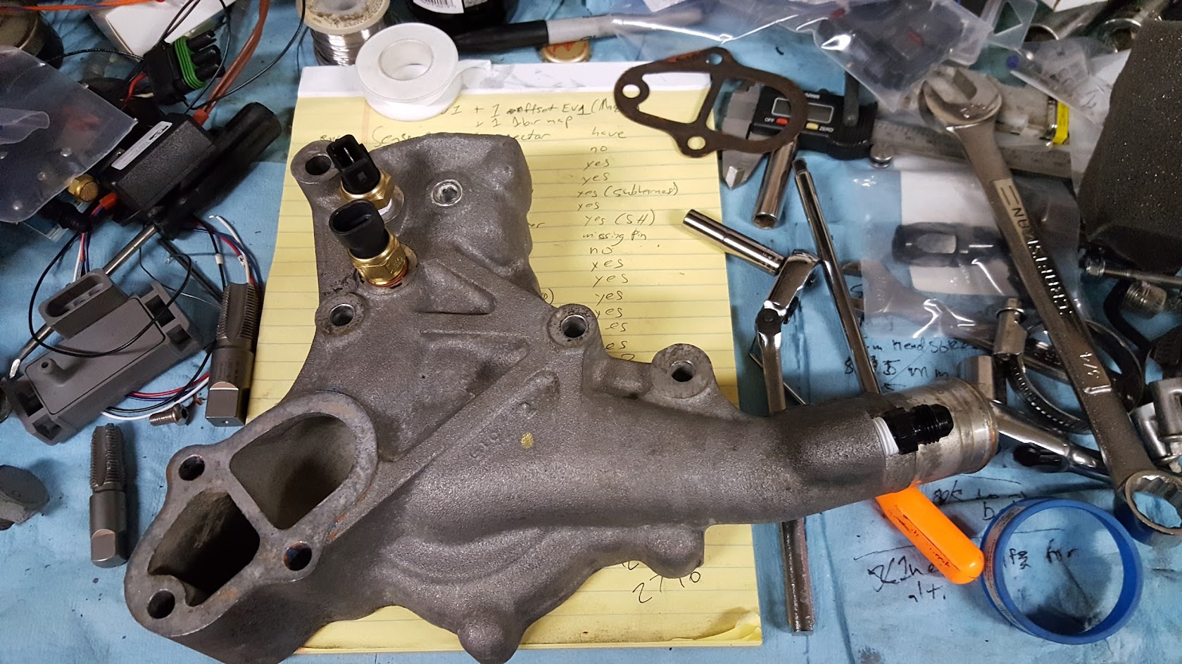
I had an issue with the new bolts I got to replace the water pump studs.... I didn't take into account that the block off plate is a but thinner, so they bottomed out. new bolts are on their way:

drilled and tapped the back of the water pump housing for new coolant temp sensors. One which is a GM coolant temp for the megasquirt (so I don't have to mess with remapping the MS from defaults) and one is for the EWP controller.
I had an issue with the new bolts I got to replace the water pump studs.... I didn't take into account that the block off plate is a but thinner, so they bottomed out. new bolts are on their way:
drilled and tapped the back of the water pump housing for new coolant temp sensors. One which is a GM coolant temp for the megasquirt (so I don't have to mess with remapping the MS from defaults) and one is for the EWP controller.
 02-14-17, 11:07 PM
#1052
Follow up to my EWP install here:
https://www.rx7club.com/3rd-generati...-flow-1110563/
mounted some stuff tonight.
4 port MAC valve for boost control. Tried to keep it out of the heat:

finished mounted the fuel pulsation damper, fuel pressure sensor, and flex fuel sensor:

https://www.rx7club.com/3rd-generati...-flow-1110563/
mounted some stuff tonight.
4 port MAC valve for boost control. Tried to keep it out of the heat:
finished mounted the fuel pulsation damper, fuel pressure sensor, and flex fuel sensor:


 02-21-17, 08:16 PM
#1054
belt size 15300 (for a racing beat smaller main pulley and an FD alternator... so probably not useful for anyone). It's 1 inch shorter than the water pump belt I had on there (which was a 15310)
anyone one know of anyone who sells single row FD alternator FC pulleys?

anyone one know of anyone who sells single row FD alternator FC pulleys?
 02-22-17, 10:29 AM
#1059
Senior Member
same here have a gm single sleeve pulley on a fd alt that was bolt on with the same diameter hole and pulley diameter..don't know the exact yr. and model since a alternator shop gave it to me...but I'm pretty sure he said it came off a 70's gm which entailed probably most of the gm line.
Last edited by Nosferatu; 02-22-17 at 10:34 AM.
 02-22-17, 09:58 PM
#1061

 03-12-17, 10:31 PM
#1066
slow and steady...
remade that coil bracket... still not 100% pleased, but it'll do for now.
not sure if I ever showed pictures of this. but I mounted 2 bosch knock sensors using elite rotary studs. The studs reduce from 10mm to 8mm so you can use standard knock sensors.

I started on ECU mounting. This is an attempt to finally do this "the right way" (4th times the charm?). I made a plate that will bolt to the stock ECU bracket. and I'm going to bolt everything to that:
The plan with the suspicious empty space:

So far I have mounting holes for the ECU and a strap for the WBO2 (which annoyingly has no way to mount it, so it gets a hose clamp through two slots in the plate.)

remade that coil bracket... still not 100% pleased, but it'll do for now.
not sure if I ever showed pictures of this. but I mounted 2 bosch knock sensors using elite rotary studs. The studs reduce from 10mm to 8mm so you can use standard knock sensors.
I started on ECU mounting. This is an attempt to finally do this "the right way" (4th times the charm?). I made a plate that will bolt to the stock ECU bracket. and I'm going to bolt everything to that:
The plan with the suspicious empty space:
So far I have mounting holes for the ECU and a strap for the WBO2 (which annoyingly has no way to mount it, so it gets a hose clamp through two slots in the plate.)

 Mine just happens to be an LS one... I did have to take a lot of wires out of the harness though haha. I do like the AMP seal connectors... they're much nicer to deal with than the old DB-37s.
03-14-17, 10:45 AM
Mine just happens to be an LS one... I did have to take a lot of wires out of the harness though haha. I do like the AMP seal connectors... they're much nicer to deal with than the old DB-37s.
03-14-17, 10:45 AM
#1071
I'm using the sharpie in you pic as a yardstick, but the ECU looks compact. About 7x8x2 maybe?
I am looking at getting that ECU down the road over the MS3X kit, so could you measure it for me?
Also, do you know if the false floor fits over the whole ECU panel without hitting anything?
I am looking at getting that ECU down the road over the MS3X kit, so could you measure it for me?
Also, do you know if the false floor fits over the whole ECU panel without hitting anything?
03-17-17, 07:24 PM
#1072
I'm using the sharpie in you pic as a yardstick, but the ECU looks compact. About 7x8x2 maybe?
I am looking at getting that ECU down the road over the MS3X kit, so could you measure it for me?
Also, do you know if the false floor fits over the whole ECU panel without hitting anything?
I am looking at getting that ECU down the road over the MS3X kit, so could you measure it for me?
Also, do you know if the false floor fits over the whole ECU panel without hitting anything?
You might be able to get the stock cover to fit, but the way I'm laying it out, ice given up on it to make room for other things. I might make a new one.
04-05-17, 10:31 AM
#1074
So, I took a couple days off work to wire the engine... best vacation ever 
I've gotten most of it done. Like I probably mentioned earlier I'm building this harness with as little solder joints as possible. So far I've only had to do 3, which was replacing the gold box crank trigger wires with a shielded wire:
https://www.diyautotune.com/product/...0-gauge-10-39/
I've been lucky enough to source new replacement connectors and pins for all of the sensors on my engine, mostly because at this point none of them are stock anymore...
start of the madness:

crimping pins onto the wire:


halfway through the first harness (sensor harness):

connecting up the 5V references (TPS,fuel pressure, and MAP get 5v) and sensor grounds with adhesive lined heat shrink butt connectors.

shrunk:

moving onto the second harness (ECU grounds, ignition, injectors and PWM valves):

I terminated the ignition wires into a weather pack. I'm going to make a sub-harness to connect the IGN-1As up:

where I left off... I still need to run 12V power to things and then wrap up the harness in some loom stuff:

I've gotten most of it done. Like I probably mentioned earlier I'm building this harness with as little solder joints as possible. So far I've only had to do 3, which was replacing the gold box crank trigger wires with a shielded wire:
https://www.diyautotune.com/product/...0-gauge-10-39/
I've been lucky enough to source new replacement connectors and pins for all of the sensors on my engine, mostly because at this point none of them are stock anymore...
start of the madness:
crimping pins onto the wire:
halfway through the first harness (sensor harness):
connecting up the 5V references (TPS,fuel pressure, and MAP get 5v) and sensor grounds with adhesive lined heat shrink butt connectors.
shrunk:
moving onto the second harness (ECU grounds, ignition, injectors and PWM valves):
I terminated the ignition wires into a weather pack. I'm going to make a sub-harness to connect the IGN-1As up:
where I left off... I still need to run 12V power to things and then wrap up the harness in some loom stuff:
04-05-17, 10:52 AM
#1075
I also made some spark plug wires since the IGN-1A coils have a different end on them and are in a different place.
It wasn't too bad, you just need wire, ends, and a crimper tool:
https://www.summitracing.com/parts/msd-34019/overview/
https://www.summitracing.com/parts/msd-8850/overview/
https://www.summitracing.com/parts/msd-3503/overview/
and you end up with fancy customer wires:


It wasn't too bad, you just need wire, ends, and a crimper tool:
https://www.summitracing.com/parts/msd-34019/overview/
https://www.summitracing.com/parts/msd-8850/overview/
https://www.summitracing.com/parts/msd-3503/overview/
and you end up with fancy customer wires: