
4-Rotor FC Build


Thread Starter
Joined: Oct 2010
Posts: 605
Likes: 13
From: The Netherlands
Sucks to hear about the e shaft. But to be honest, IMHO, I would think you sort of have to expect and plan for bumps like this when you take on full fab project of this scope. But you don't have to defend that when crap happens, it still sucks and costs money you'd hoped to not have spent.
If it was me, I wouldn't risk damaging all the other fine pieces you've machined. Not to mention no one would want to see me destroy perfectly good housings and irons
If it was me, I wouldn't risk damaging all the other fine pieces you've machined. Not to mention no one would want to see me destroy perfectly good housings and irons
You've got mail
Iiieuuw!
smallUpdate
Currently still working on the front pully's, which is probably one of the last things I'll do to the engine before I'm going to get the shell over and start mounting the engine and doing the intake and exhaust systems.
Front pully's are going to look like this:

Not double sheave or anything, I wanted to keep things as simple, small and lightweight as possible.
Main pully is done and waterpump pully is about 75% done.
Also finally found an ECU
 , I wanted something affordable with a decent interface, something that can control a servo for a possible variable intake system in the future and sequential injection. I first wanted to go with a kdfi (basically a megasquirt, http://www.kdfi.org/), but I think I've found something better. I'll keep the make and model to myself untill I know if it works, because nobody has ever used one on a rotary before. Only downside to it is that it's only got 4 ignition outputs, so no split ignition timing when using direct coils on a 4-rotor like I'm going to. I'm n/a and like to keep things simple so I don't mind.

Senior Member

Joined: Apr 2009
Posts: 606
Likes: 80
From: netherlands
Couldn't you better go for ribbed belts instead of V-belts if u dont want to go with a dual pully?
Would be a shame if something went wrong with the altenator, slips and snaps... as it is also the belt for the waterpump..
Would be a shame if something went wrong with the altenator, slips and snaps... as it is also the belt for the waterpump..
Thread Starter
Joined: Oct 2010
Posts: 605
Likes: 13
From: The Netherlands
Ribbed belts are larger, heavier, and can also snap. If my belt snaps my alternator stops and my battery warning light comes on instantly, so I'll know immediatly.
Senior Member
Joined: Apr 2009
Posts: 606
Likes: 80
From: netherlands
Thats true,
I had issues with the altenator what aperently made it turn heavy enough to let it slip and lateron snap.
But to be honest i dont think there is a much weight difference between those 2.
I had issues with the altenator what aperently made it turn heavy enough to let it slip and lateron snap.
But to be honest i dont think there is a much weight difference between those 2.

Thread Starter
Joined: Oct 2010
Posts: 605
Likes: 13
From: The Netherlands
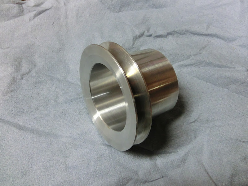
Waterpump pully almost done
, superlight and strong.It's 7075 alloy, which is often reffered to as aircraft aluminium
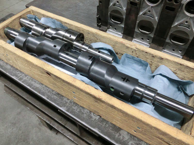
E-Shaft came back today by the way, the grinders straightened it and ground the main bearing surfaces. Did a cracking job too, looks great
. They couldn't finish it, because when setting up the machine to grind a surface they use the existing surface to set up the machine. They couldn't use the existing rotor bearing surfaces because it was unknown if the strokes of those surfaces all were within tolerance. So I picked the shaft up, set up the jig I made in the mill and started measuring.Annnd relief, all the rotor bearing surfaces are all well within specifications
, The outer ones are just under 15.015 and the middle ones are about 15.005, that's pretty good, I'm happy with that. I'll do some more measuring and compare it to a stock shaft tomorrow but after that the shaft should be free to go back to the grinders to get finished Another thing I'm happy about is that the grinders said the surface hardness was really good, they do some crankshaft modifying and send shafts out for nitrating themselves sometimes, but they were still really amazed by this one.


Joined: Mar 2001
Posts: 31,857
Likes: 3,243
From: https://www2.mazda.com/en/100th/
E-Shaft came back today by the way, the grinders straightened it and ground the main bearing surfaces. Did a cracking job too, looks great
. They couldn't finish it, because when setting up the machine to grind a surface they use the existing surface to set up the machine. They couldn't use the existing rotor bearing surfaces because it was unknown if the strokes of those surfaces all were within tolerance. So I picked the shaft up, set up the jig I made in the mill and started measuring.Annnd relief, all the rotor bearing surfaces are all well within specifications
, The outer ones are just under 15.015 and the middle ones are about 15.005, that's pretty good, I'm happy with that. I'll do some more measuring and compare it to a stock shaft tomorrow but after that the shaft should be free to go back to the grinders to get finished Another thing I'm happy about is that the grinders said the surface hardness was really good, they do some crankshaft modifying and send shafts out for nitrating themselves sometimes, but they were still really amazed by this one.


John, I am glad the E Shaft turned out to be ok! I could Imagine how demoralizing that would have been to hear the news.
I love this build, Your craftmanship is top notch!
I love this build, Your craftmanship is top notch!
Thread Starter
Joined: Oct 2010
Posts: 605
Likes: 13
From: The Netherlands
Haha your right, multiple things can be said by that sentence

Anyways, I threw the e-shaft back in the measuring fixture. I checked the stroke on multiple spots on each bearing surface and picked the best position on each for the grinders to use as reference point. I also measured an oem 13B shaft for reference and compared it. If the grinders don't mess up this will work
Also disassembled the mock-up engine, and assembled it again using a normal e-shaft in the front engine half. This allows me to see if the stuff under the front cover and the front pully's all fit together. I think it looks pretty good so far, just need to do the alternator pully
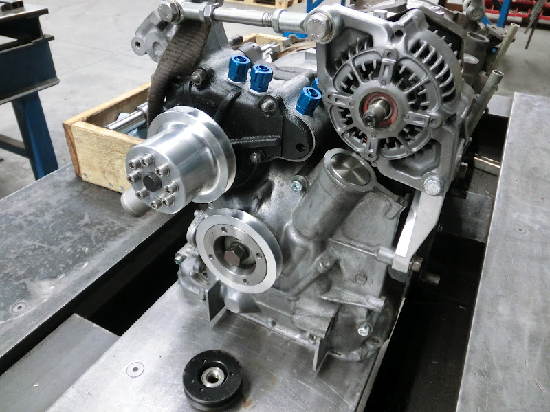
Hopefully I can finish the pully setup coming weekend. ECU, ignition coils and some needed sensors are also heading this way as we speak
Thread Starter
Joined: Oct 2010
Posts: 605
Likes: 13
From: The Netherlands
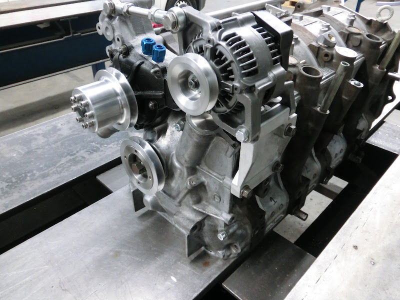
Finished the front pully setup
Also finished the fuel rail, and modified some standard fittings which now fit into the oil injector holes. I'm going to try to hook the brake booster up to these fittings.

After that I started doing the steering rack. I'm not going to be using power steering, and since manual racks are pretty tough to find over here I convered my powered rack to manual.
Here is everything taken apart, it already has the needed modifications in this picture:
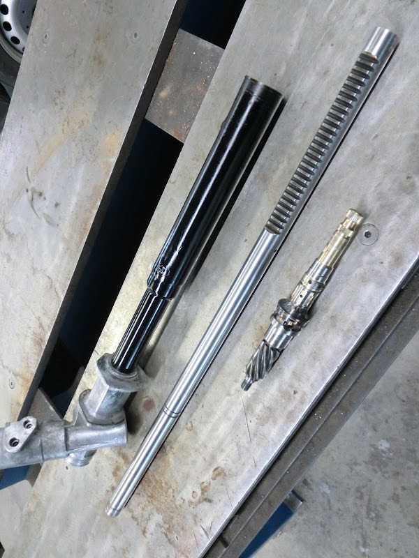
I basically removed the ring on the steering rod, removed the hydraulic fittings on the housing, and welded the input shaft. The input shaft of an powered rack can move a bit related to the drive gear, it's spring loaded and can move about 10�, it's how the hydraulic system works. This movement can cause a sloppy feel, so I welded the 2 shafts together. Be carefull if your going to do this, there are 3 bearings that hold this shaft, so the shaft needs to stay straight. I had to straighten the shaft after welding, weld on some material to the outer bearing surface, and machine that surface down again so all the 3 bearing surfaces were back in line again.
Here is everything assembled again:

Should work fine.
I think I'm going to do the exhaust flange tomorrow, also need to machine a spacer where the CAS drive gear used to be.
Also finished the fuel rail, and modified some standard fittings which now fit into the oil injector holes. I'm going to try to hook the brake booster up to these fittings.
After that I started doing the steering rack. I'm not going to be using power steering, and since manual racks are pretty tough to find over here I convered my powered rack to manual.
Here is everything taken apart, it already has the needed modifications in this picture:
I basically removed the ring on the steering rod, removed the hydraulic fittings on the housing, and welded the input shaft. The input shaft of an powered rack can move a bit related to the drive gear, it's spring loaded and can move about 10�, it's how the hydraulic system works. This movement can cause a sloppy feel, so I welded the 2 shafts together. Be carefull if your going to do this, there are 3 bearings that hold this shaft, so the shaft needs to stay straight. I had to straighten the shaft after welding, weld on some material to the outer bearing surface, and machine that surface down again so all the 3 bearing surfaces were back in line again.
Here is everything assembled again:
Should work fine.
I think I'm going to do the exhaust flange tomorrow, also need to machine a spacer where the CAS drive gear used to be.
Thread Starter
Joined: Oct 2010
Posts: 605
Likes: 13
From: The Netherlands

Still toying with the idea of a variable intake.
Problem is that with fitment restrictions I can only make it variable over a small range. The design as pictures above can adjust the intake length from 24,5" to 19,8"
It would make dyno tuning a lot of fun though, and I think it will affect the torque curve quite a bit, so I might just give it a go.

looking good John, making good progress!
i did the same mod to my steering rack.. is yours S4 or S5? S4 is harder to turn due to the ratio.
and you should plug or weld those holes shut
i did the same mod to my steering rack.. is yours S4 or S5? S4 is harder to turn due to the ratio.
and you should plug or weld those holes shut
Senior Member
Joined: Aug 2008
Posts: 493
Likes: 0
From: Belgium (2800)
mmmh can't you do something with 2 linear actuators for de variable intake.
I think you can modify it so its a little bit faster:

I think you can modify it so its a little bit faster:
i would just make a universal clamp on TB setup and worry about the adjustable length system a little later on. best to break things up into sections expecting issues to arise.
Joined: Mar 2001
Posts: 31,857
Likes: 3,243
From: https://www2.mazda.com/en/100th/
+1. if you do clamp on at first you can pick a couple of lengths that work for the power band you want