
My Semi-PP Intake Manifold

Thread Starter
Senior Member
Joined: Nov 2007
Posts: 343
Likes: 0
From: Australia
My Semi-PP Intake Manifold
Hey guys,
Not sure if this is the right section for this but i've had a few enquiries about my intake for my semi-peripheral port engine so i figured i'd do a mini build thread showing how i went about it. I used an xcessive LIM to try and get the flow to each housing as close to parity as possible and i added in peripheral port runners that merged into the secondary runners.
For those who don't know what an Xcessive LIM looks like (where the hell have you been hiding if these people even exist?):
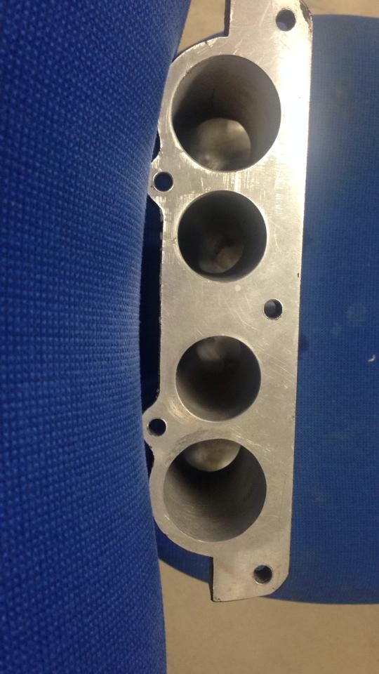
Engine side:

Strut tower side:

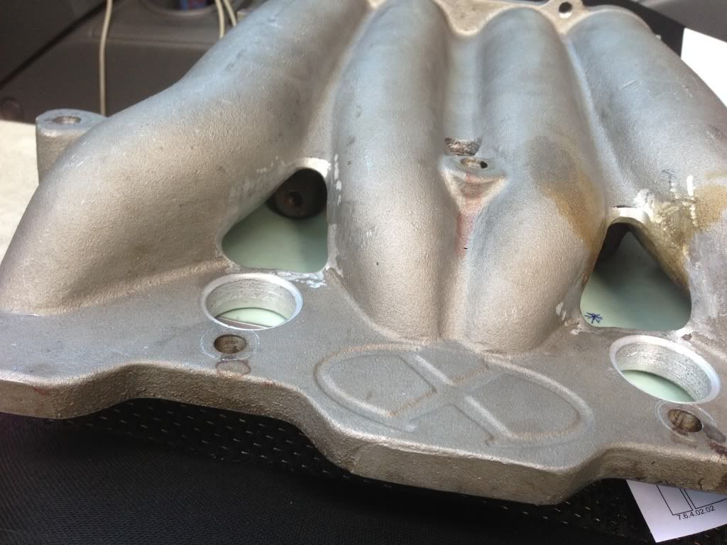
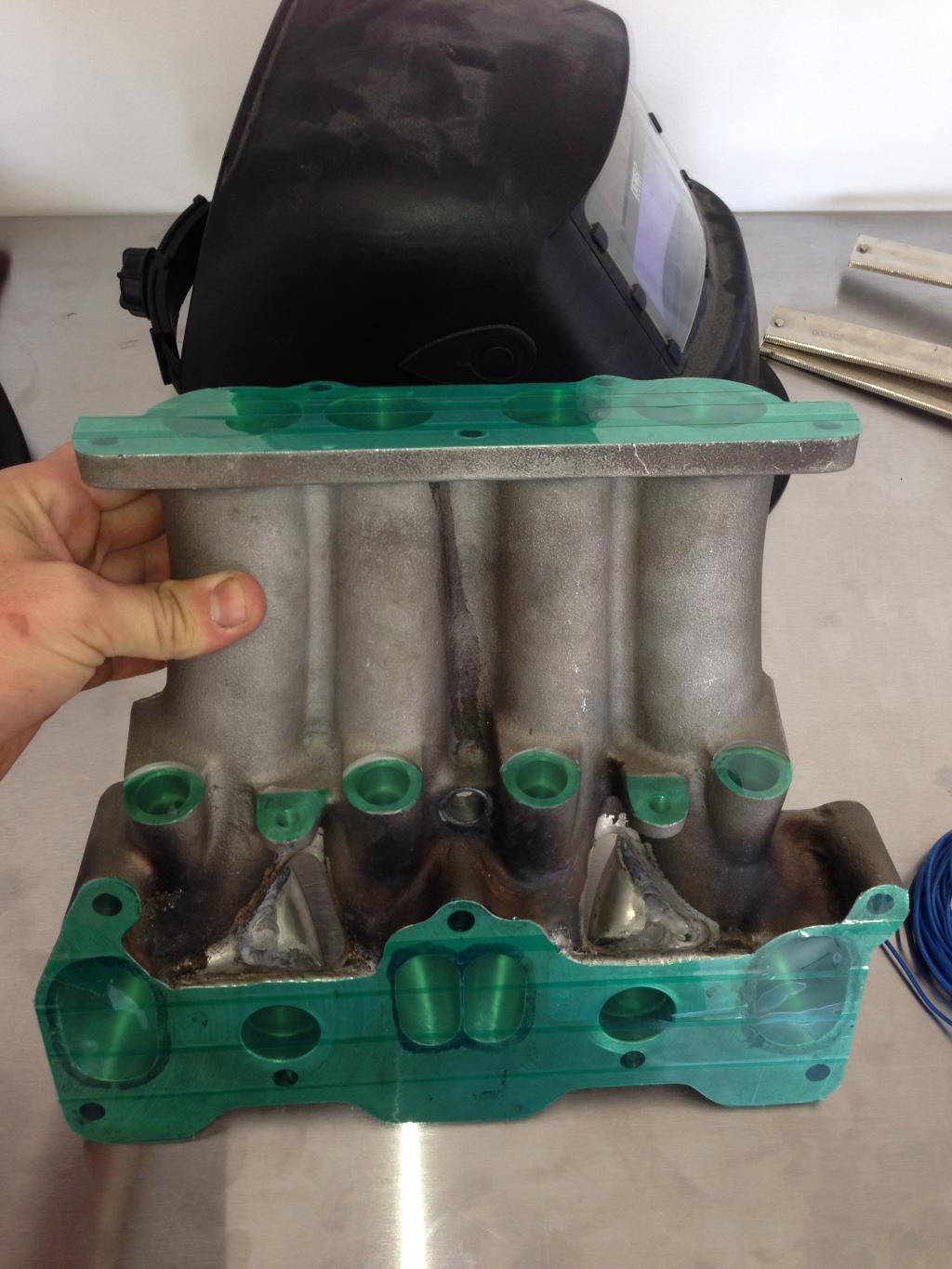
You'll notice that the engine face of the manifold has valleys (for lack of a better term) between the primary and secondary ports; the first thing i did was have these welded up and the surface faced so that it was true. After this i took to the areas between the secondary and primary ports (near the base) with a die grinder to remove the material in preperation for the peripheral port runners. From here the next step was to grab an old rotor housing and to pinpoint the centre of the hollow in relation to the centre of the stud below it to determine where i needed to mark mating surface of the manifold for drilling.
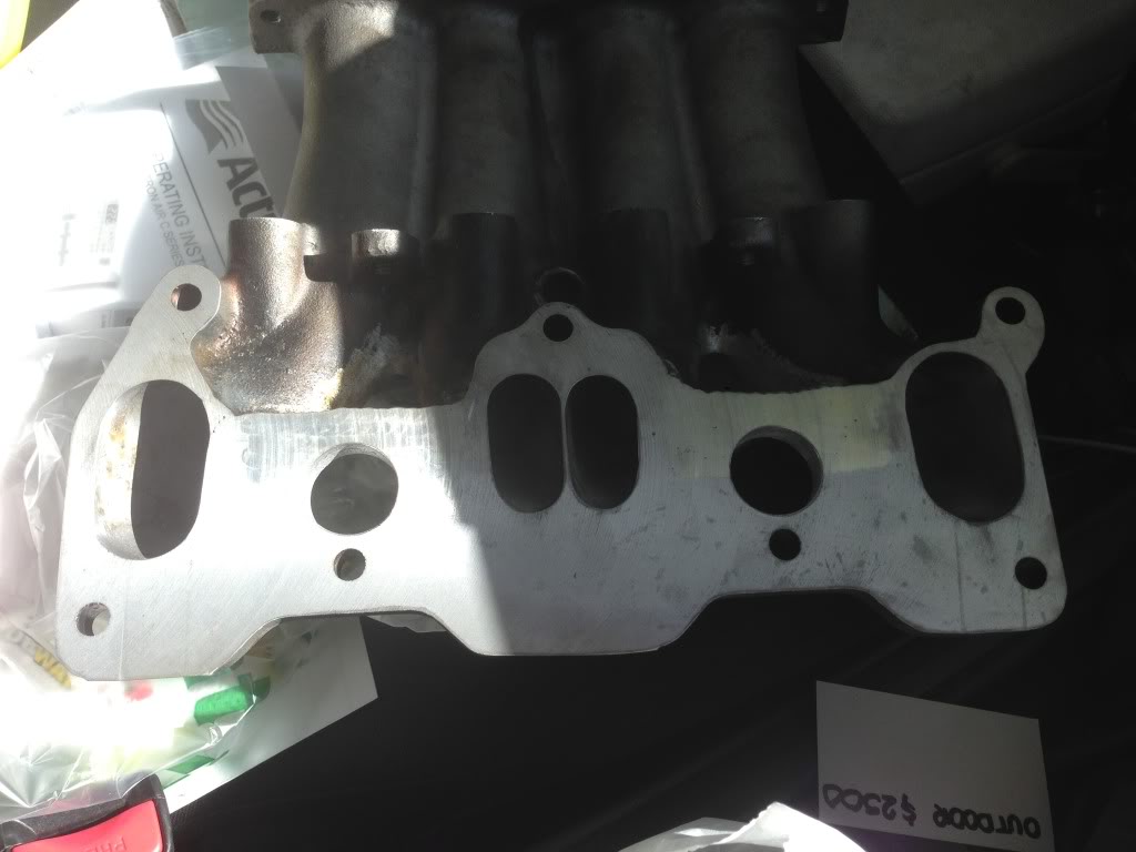
To size the holes and ultimately the p-port runners i found some tight radius aluminium bends that had a CLR (centre line radius) that would suit the distance from the LIM lower flange to the outside of the cast runners where i wanted the runners to merge in. Once i knew the outside size of the tube i was going to use i had a local shop machine a hole the same size as the ID of the tube and a lip around the edge the same size as the OD of the tube.
Like so:
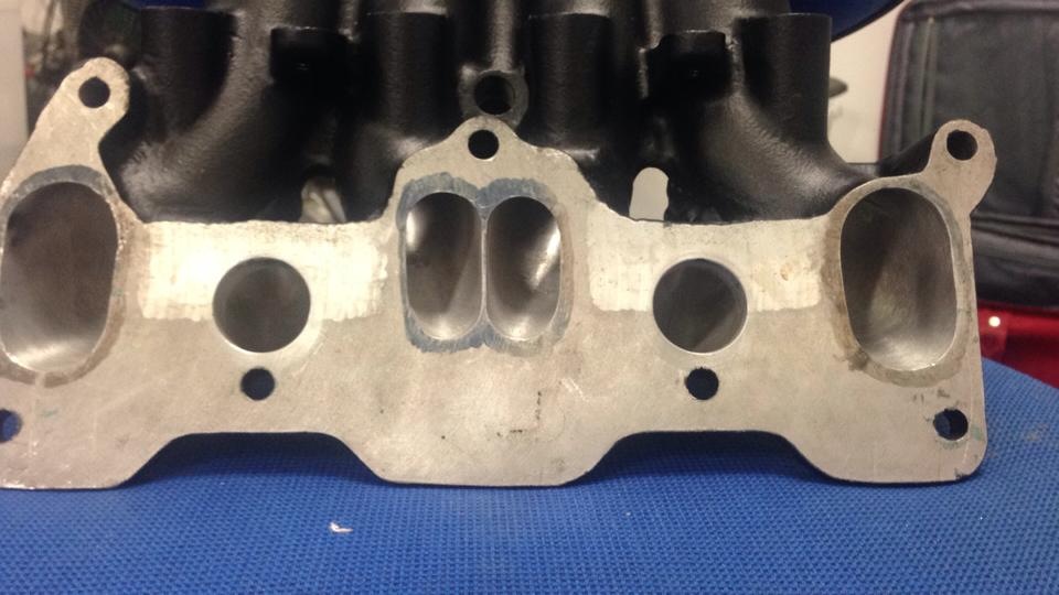
front view (ignore my medicore porting please):
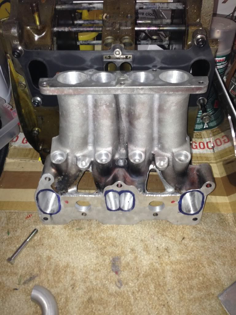
From here it was just a matter of welding some tube onto the tight radius donut halves and drilling some holes into the secondary runners at the right height and welding the runners in place. Heres the end result:
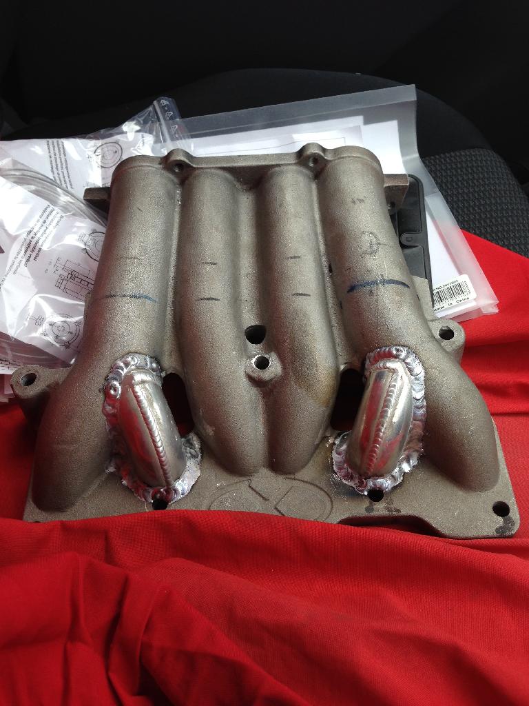
After this all that was needed was some die grinding to smooth the transitions and tape up the faces ready for powdercoating:
I didn't really think to get any decent pictures of the manifold before i installed it sadly but here's some crappy ones showing my terrible porting and not really showing enough down the runners haha:
But hey it works/braps!:

Not sure if this is the right section for this but i've had a few enquiries about my intake for my semi-peripheral port engine so i figured i'd do a mini build thread showing how i went about it. I used an xcessive LIM to try and get the flow to each housing as close to parity as possible and i added in peripheral port runners that merged into the secondary runners.
For those who don't know what an Xcessive LIM looks like (where the hell have you been hiding if these people even exist?):
Engine side:
Strut tower side:
You'll notice that the engine face of the manifold has valleys (for lack of a better term) between the primary and secondary ports; the first thing i did was have these welded up and the surface faced so that it was true. After this i took to the areas between the secondary and primary ports (near the base) with a die grinder to remove the material in preperation for the peripheral port runners. From here the next step was to grab an old rotor housing and to pinpoint the centre of the hollow in relation to the centre of the stud below it to determine where i needed to mark mating surface of the manifold for drilling.
To size the holes and ultimately the p-port runners i found some tight radius aluminium bends that had a CLR (centre line radius) that would suit the distance from the LIM lower flange to the outside of the cast runners where i wanted the runners to merge in. Once i knew the outside size of the tube i was going to use i had a local shop machine a hole the same size as the ID of the tube and a lip around the edge the same size as the OD of the tube.
Like so:

front view (ignore my medicore porting please):


From here it was just a matter of welding some tube onto the tight radius donut halves and drilling some holes into the secondary runners at the right height and welding the runners in place. Heres the end result:

After this all that was needed was some die grinding to smooth the transitions and tape up the faces ready for powdercoating:

I didn't really think to get any decent pictures of the manifold before i installed it sadly but here's some crappy ones showing my terrible porting and not really showing enough down the runners haha:


But hey it works/braps!:


That looks great! Only question I had was how well you can tighten those lower middle mounting bolts. It looks like the weld bead would get in the way of the bolt seating flat.
Thread Starter
Senior Member
Joined: Nov 2007
Posts: 343
Likes: 0
From: Australia
Brad.
Thread Starter
Senior Member
Joined: Nov 2007
Posts: 343
Likes: 0
From: Australia
S4 T2 rotors
Balanced rotating assembley
CNCed rotor chamber for uniform 7.9:1 compression ratio
28mm semi peripheral ports
12.7mm stud kit
Screw in welch plugs
Rx8 rear stationary gear
Xtreme rotaries apex and corner seals
Link G4 ecu running it all; bottle neck for the car will be the T04z
Balanced rotating assembley
CNCed rotor chamber for uniform 7.9:1 compression ratio
28mm semi peripheral ports
12.7mm stud kit
Screw in welch plugs
Rx8 rear stationary gear
Xtreme rotaries apex and corner seals
Link G4 ecu running it all; bottle neck for the car will be the T04z
Trending Topics


Rotary for life!
Joined: Oct 2005
Posts: 1,155
Likes: 1
From: Somewhere...
Latest update in November - FD-RX7 Enthusiasts Forum
Thread Starter
Senior Member
Joined: Nov 2007
Posts: 343
Likes: 0
From: Australia
not a great deal sorry guys, car made 384hp on 17psi here in aus with slipping clutch; cars getting pulled apart this weekend for install of new setrab 25 row coolers and proper ducting; i'll take some pics and throw them up here when i do over the weekend 
Brad.
Brad.
Thanks for the update. Do you think the semi pp was worth it?

Thread
Thread Starter
Forum
Replies
Last Post
rgordon1979
3rd Generation Specific (1993-2002)
40
Mar 15, 2022 12:04 PM