
Engine Removal, Rebuild, and Install on a 95 RHD FD


Thread Starter
Full Member
Joined: Jan 2015
Posts: 59
Likes: 2
From: K-Town, Germany
How to Release the Throw-Out Bearing
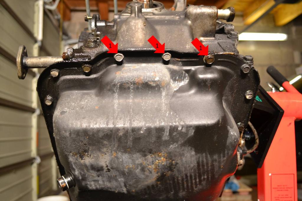
First off, you have to remove the access plate on the bottom of the transmission to even get to the throw-out-bearing (TOB) retainer.
1: Remove these bolts.

Once those bolts are out, you can look up through the hole and see the clutch pressure plate, retainer, and TOB. This picture shows the actual retainer ring. This is the ring you will have to press into the pressure plate.

This is what the ring looks like when it is extended, in this position the TOB is locked into the pressure plate. You can see there is a gap between the ring and pressure plate, represented by the 3 very small arrows.
1: Put pressure in the direction of these arrows, and work your way around the ring. I found it super easy to just stick a screwdriver between the retainer and TOB and twist. Twisting the screwdriver will press the retainer in.

This is the retainer pressed in, you can see how there is no longer a gap. Once you press the retainer in like this the TOB will automatically snap out due to the clutch fork being spring loaded. As soon as you see the TOB pop back towards the transmission, you know that it has been released.

Perfect, thank you!
I tried that with my car with no luck, I will get my wife to turn the engine slowly so I can work my way around it pushing it in. I can fit my hand in that tiny little hole. lol
I tried that with my car with no luck, I will get my wife to turn the engine slowly so I can work my way around it pushing it in. I can fit my hand in that tiny little hole. lol
Thread Starter
Full Member
Joined: Jan 2015
Posts: 59
Likes: 2
From: K-Town, Germany
I would use a long screwdriver or pry bar to reach in the hole and press the retainer. I only had to push in two spots to release mine. Basically 180 degrees apart. But I'm guessing that varies depending on how much crap is built up on the retainer and TOB.
Thread Starter
Full Member
Joined: Jan 2015
Posts: 59
Likes: 2
From: K-Town, Germany
Season 2 - Episode 1
Alrighty, on to Season 2: The Tear-Down.
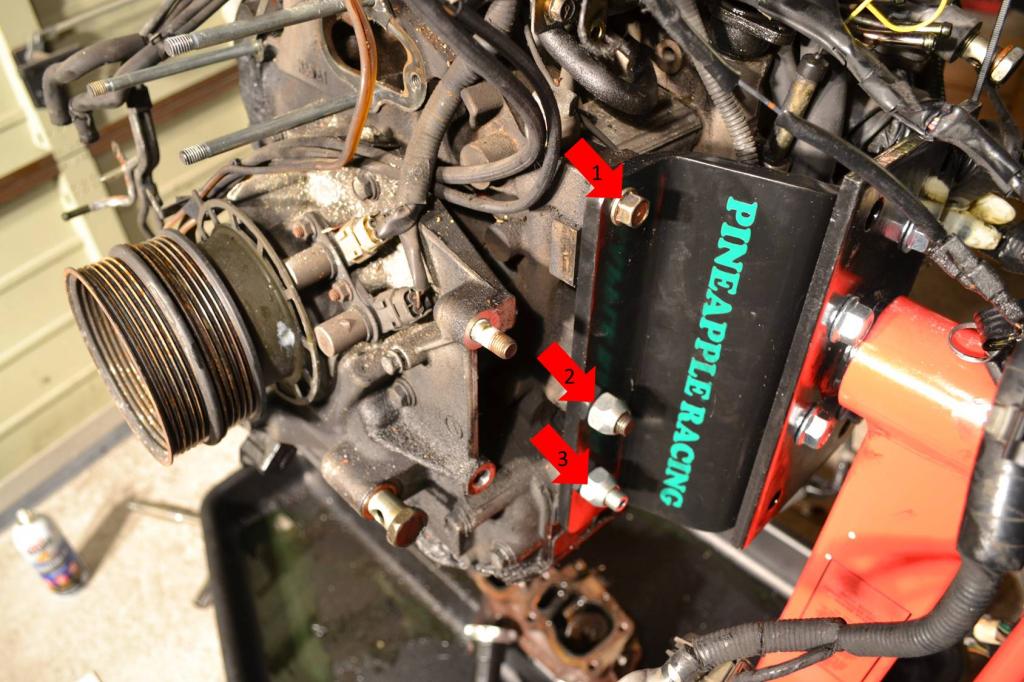
I know a lot of people don't actually use an adapter to hang the engine on a stand. But I did, I bought the adapter from Pineapple Racing. Nice adapter, but I had to modify my engine stand to make it work. That's cool though. It bolts up to the motor easily. Overall, it's an easy-to-use bracket.
1: This is just one of the accessory bracket bolts.
2: This stud is on the engine already. Pineapple Racing supplies the nut.
3: This stud and nut are supplied by Pineapple Racing.
Once I got the engine on the stand I started to tear the engine down. I began by pulling the clutch off. The engine was actually on the ground at this point. But we'll pretend it was on the stand.
1: Remove these six bolts. The pressure plate and clutch disc will come loose. Just set them aside.
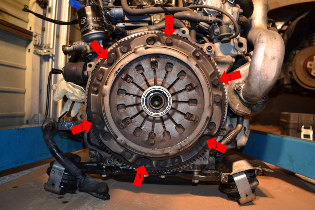
I left the flywheel in place. I will need it there later anyways, plus, I don't have my 54mm socket in yet. Still waiting on the vendor for that one.
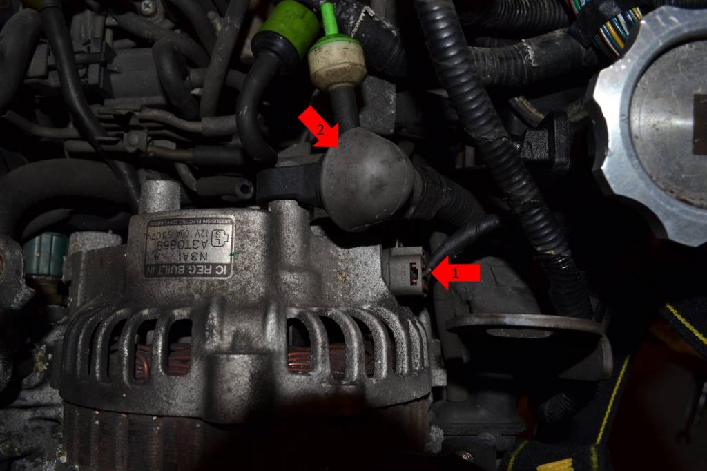
Remove the alternator next.
1: Remove this plug.
2: Move this rubber boot. Underneath there will be a 12mm nut securing a wire. Remove the nut and wire. Then put the nut back on the stud.
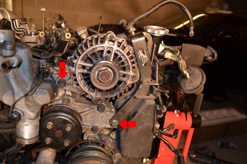
1: Remove these two bolts. The alternator will then come loose and can be set aside.
Now move on to pulling the turbo and exhaust manifold.
1: Remove these two nuts securing the rear compressor's intake pipe. Lay the pipe aside.

1: Remove the two nuts securing the discharge pipe to the front compressor.
2: Remove this vacuum line.
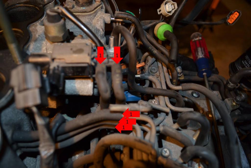
1: Remove these vacuum lines.
2: Remove the two nuts securing the discharge pipe to the rear compressor.
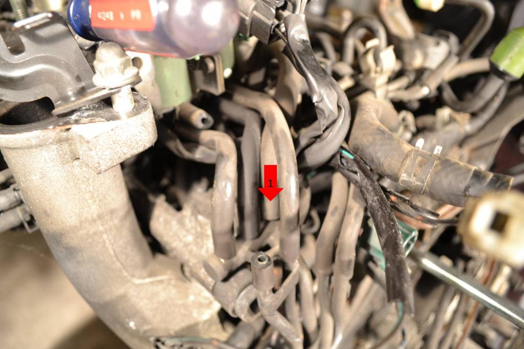
1: Remove this vacuum line. The entire discharge pipe is now free, set it aside.
1: Remove these two bolts and one nut that secure the heat shield. Set it aside.
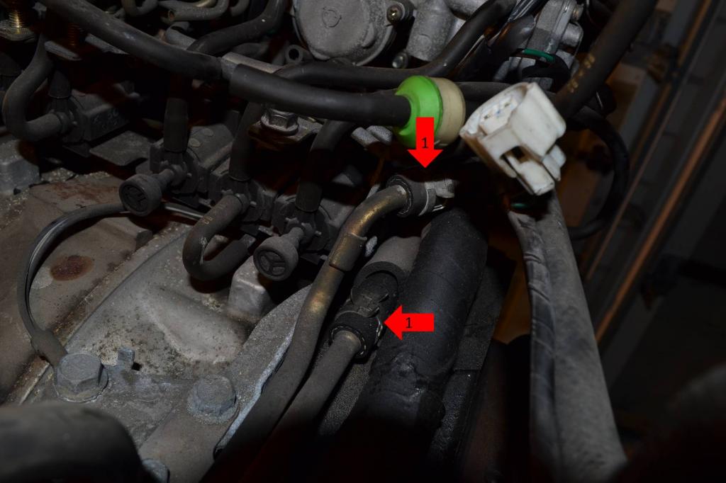
1: Remove the oil feed line.
2: Remove this coolant line.
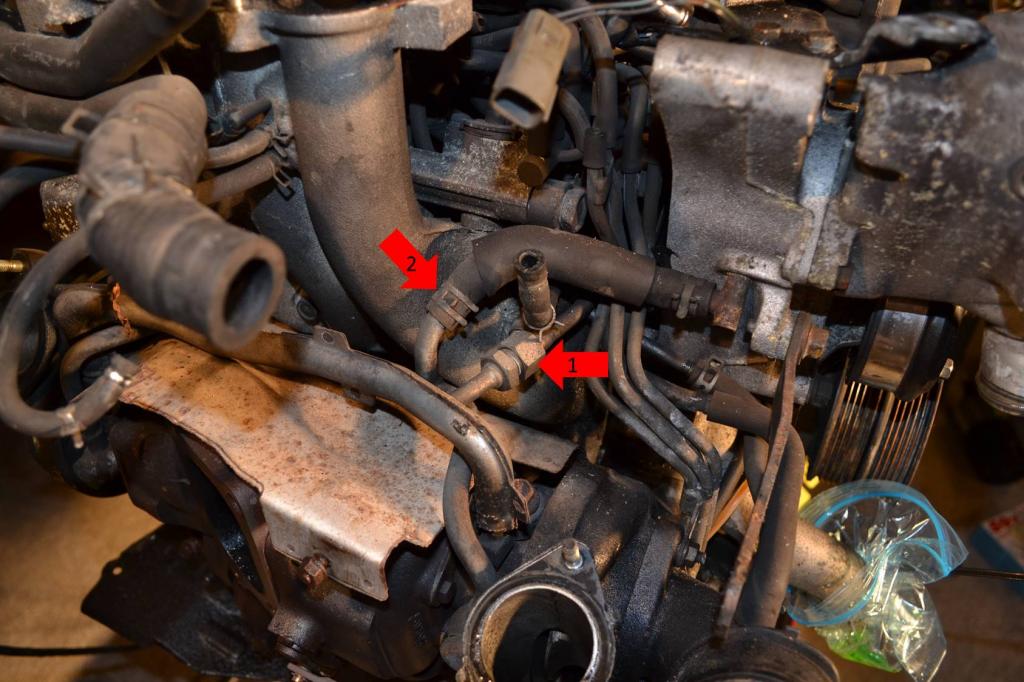
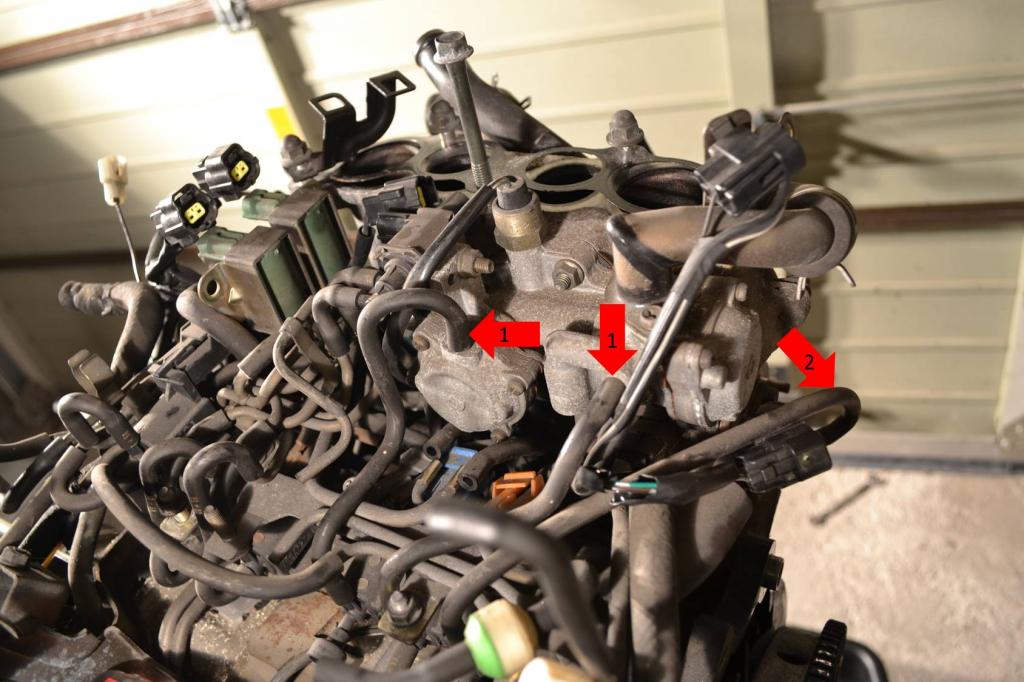
Alright, a lot going on in this picture.
1: Remove both of these lines.
2: Remove this coolant line.
3: Remove all of these vacuum lines.
4: Remove these two nuts and remove the vacuum hard-line bracket. Once you do that, you can put the nuts back on.
1: Remove the two bolts securing the front oil return.
To be continued next post.
I know a lot of people don't actually use an adapter to hang the engine on a stand. But I did, I bought the adapter from Pineapple Racing. Nice adapter, but I had to modify my engine stand to make it work. That's cool though. It bolts up to the motor easily. Overall, it's an easy-to-use bracket.
1: This is just one of the accessory bracket bolts.
2: This stud is on the engine already. Pineapple Racing supplies the nut.
3: This stud and nut are supplied by Pineapple Racing.

Once I got the engine on the stand I started to tear the engine down. I began by pulling the clutch off. The engine was actually on the ground at this point. But we'll pretend it was on the stand.
1: Remove these six bolts. The pressure plate and clutch disc will come loose. Just set them aside.

I left the flywheel in place. I will need it there later anyways, plus, I don't have my 54mm socket in yet. Still waiting on the vendor for that one.
Remove the alternator next.
1: Remove this plug.
2: Move this rubber boot. Underneath there will be a 12mm nut securing a wire. Remove the nut and wire. Then put the nut back on the stud.

1: Remove these two bolts. The alternator will then come loose and can be set aside.

Now move on to pulling the turbo and exhaust manifold.
1: Remove these two nuts securing the rear compressor's intake pipe. Lay the pipe aside.

1: Remove the two nuts securing the discharge pipe to the front compressor.
2: Remove this vacuum line.

1: Remove these vacuum lines.
2: Remove the two nuts securing the discharge pipe to the rear compressor.

1: Remove this vacuum line. The entire discharge pipe is now free, set it aside.

1: Remove these two bolts and one nut that secure the heat shield. Set it aside.

1: Remove the oil feed line.
2: Remove this coolant line.

Alright, a lot going on in this picture.
1: Remove both of these lines.
2: Remove this coolant line.
3: Remove all of these vacuum lines.
4: Remove these two nuts and remove the vacuum hard-line bracket. Once you do that, you can put the nuts back on.

1: Remove the two bolts securing the front oil return.

To be continued next post.
Thread Starter
Full Member
Joined: Jan 2015
Posts: 59
Likes: 2
From: K-Town, Germany
Season 2 - Episode 1 Continued
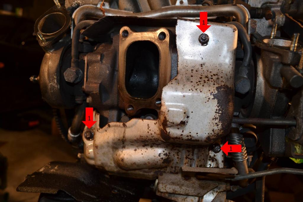
Ok, continuing the removal of the turbo.
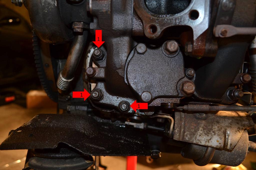
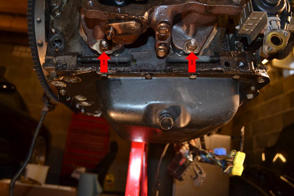
1: Remove the two bolts securing the rear oil return.
1: Remove these three nuts.
2: Remove these two bolts.
1: Remove these three nuts. The entire turbo assembly is now free and can be set aside.
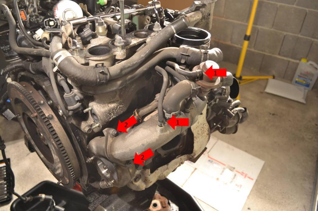
Now to remove the exhaust manifold.
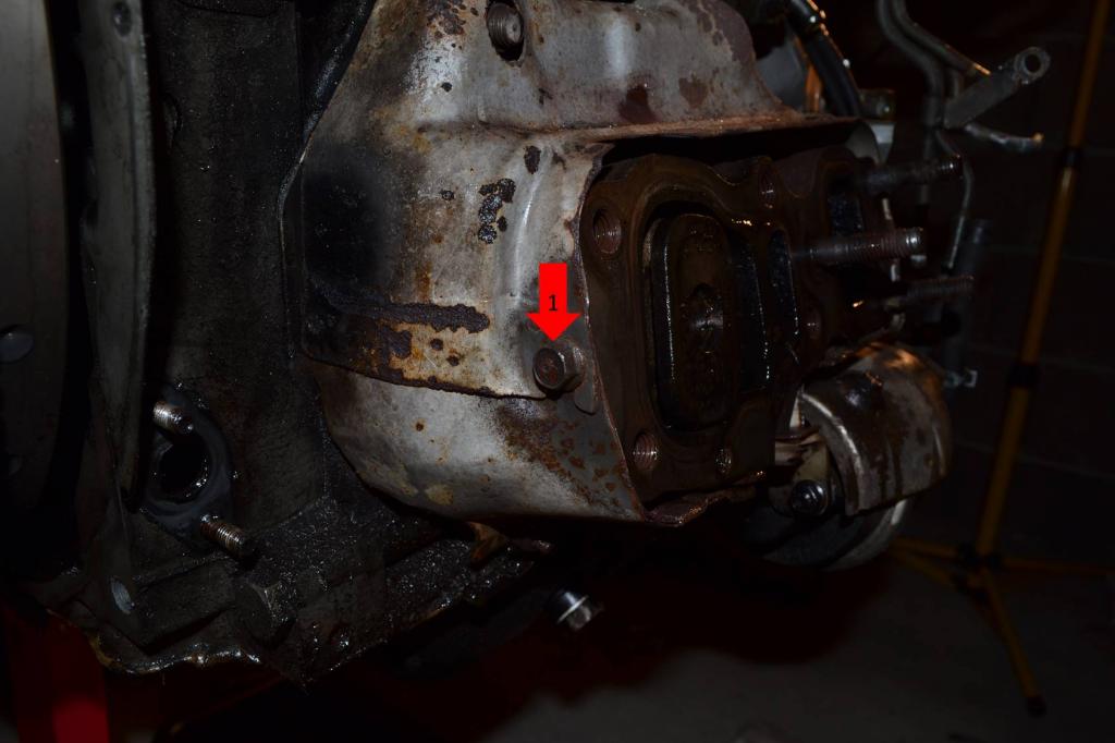
1: Remove this bolt on the heat shield.
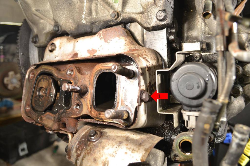
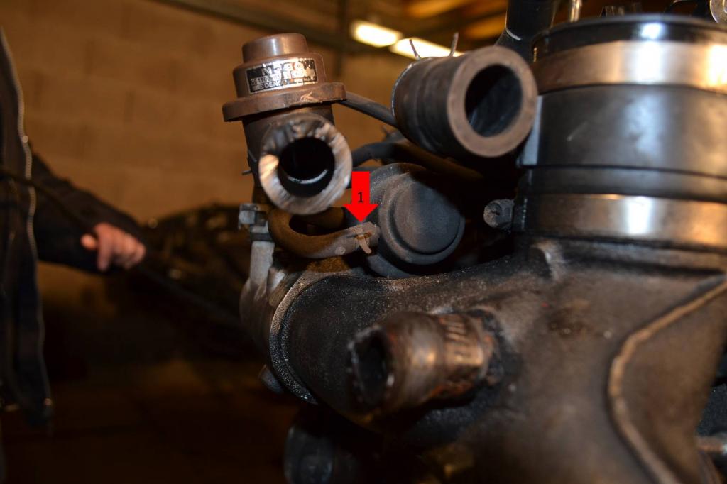
1: Remove this bolt on the heat shield.
1: Remove the clip securing the actuator rod.
2: Remove these two bolts securing the actuator and the last nut securing the heat shield. Both the actuator and heat shield can be set aside.
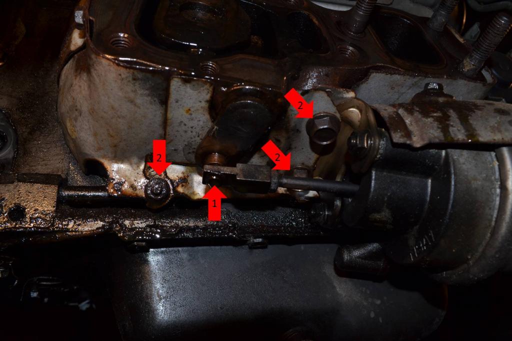
1: Remove these two nuts.
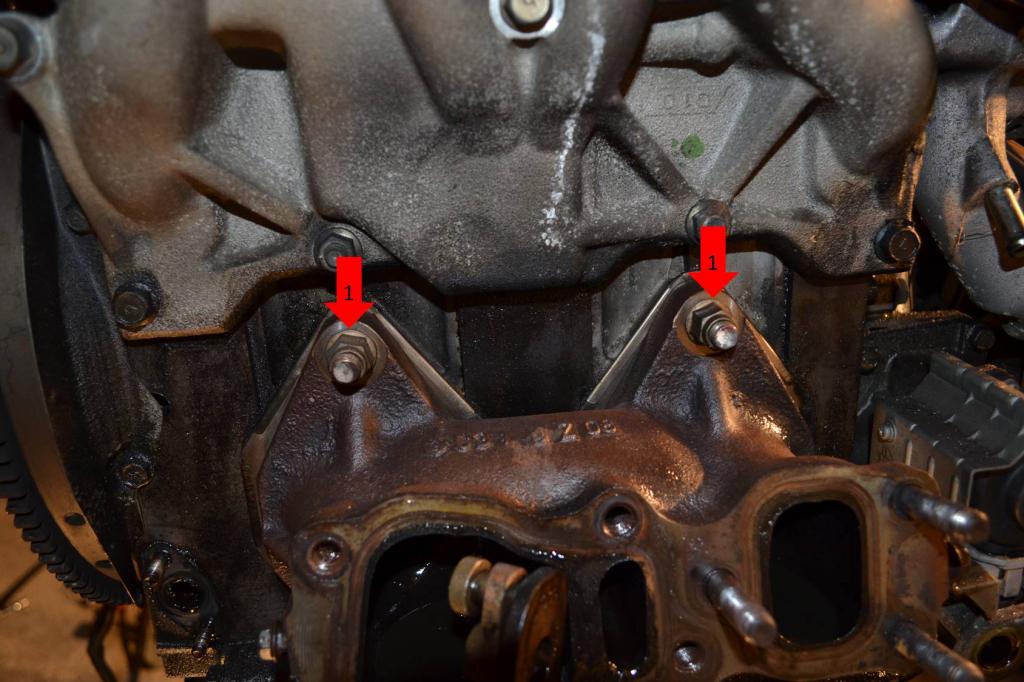
1: Remove these two nuts. The exhaust manifold will now come off and can be set aside.
Now remove both motor mounts.
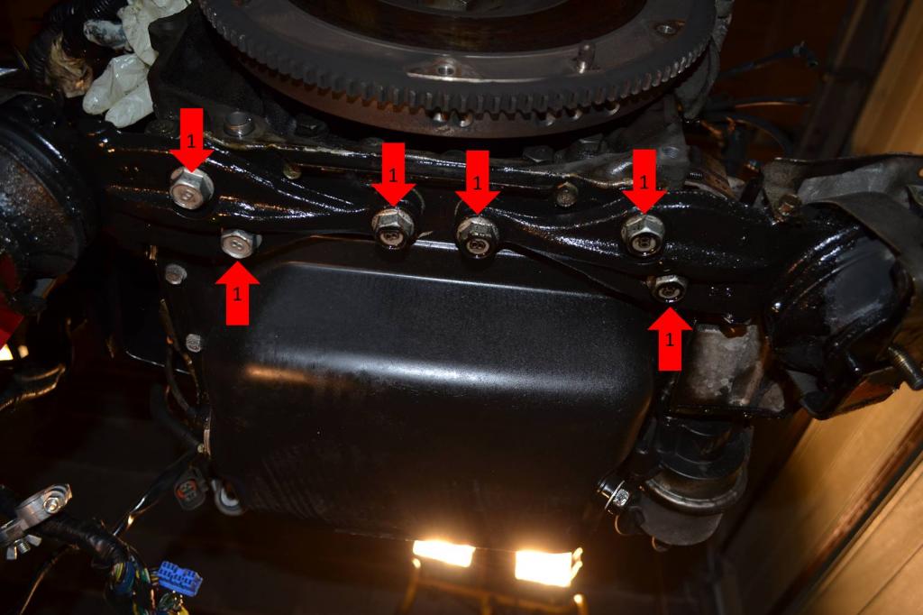
1: Remove all six bolts. There are three on each mount. Once removed, the mounts can be set aside.
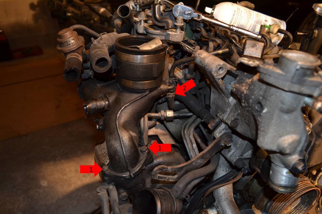
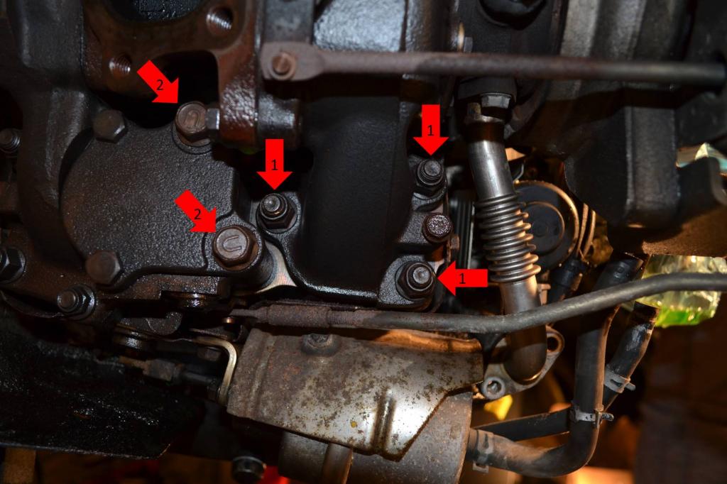
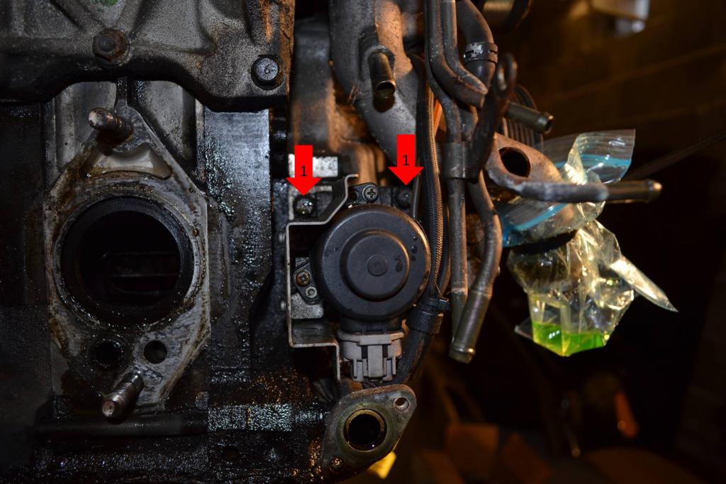
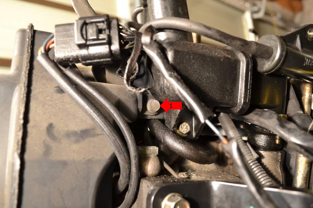
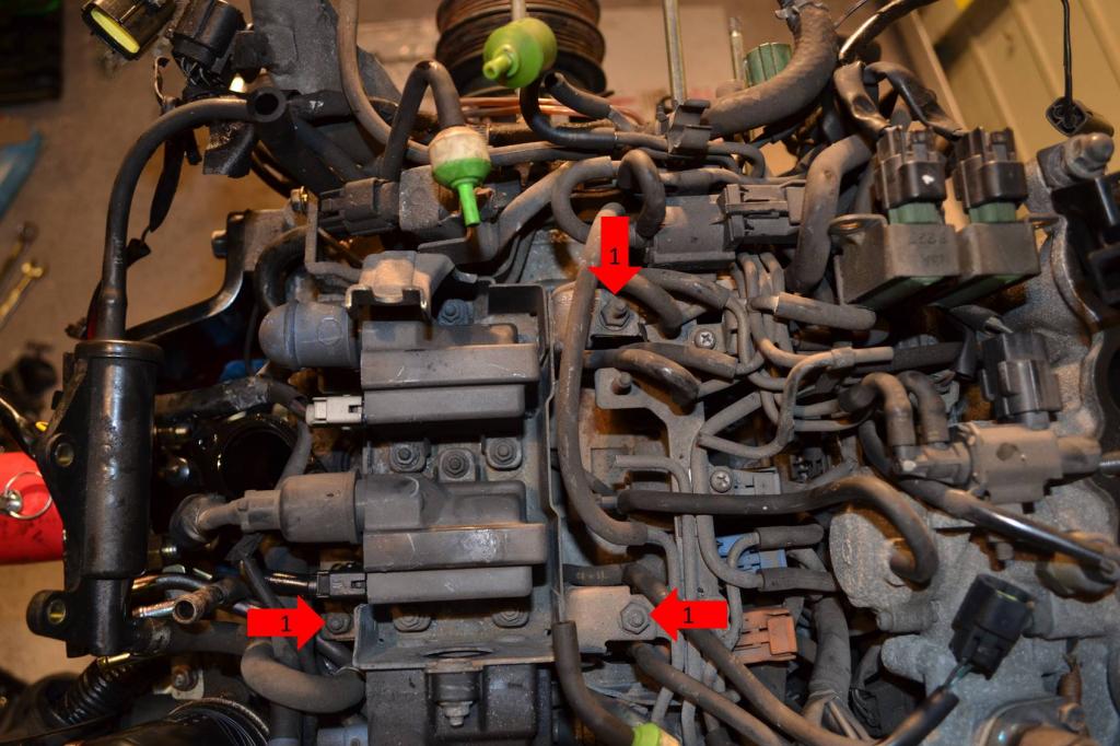
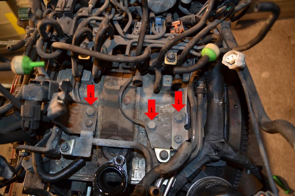
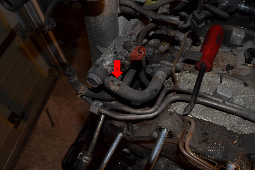
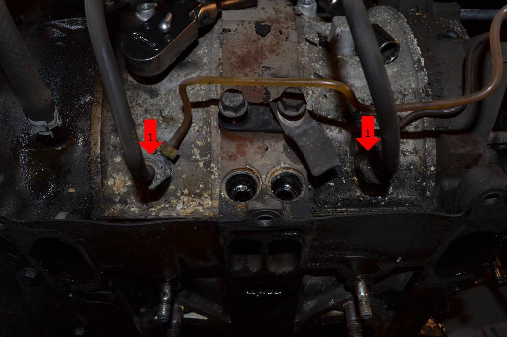
Alright, move on to the Oil Metering Pump (OMP) now.
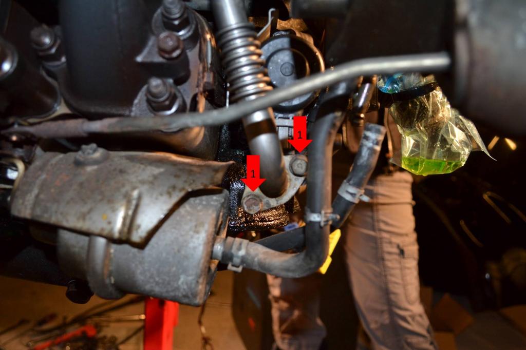
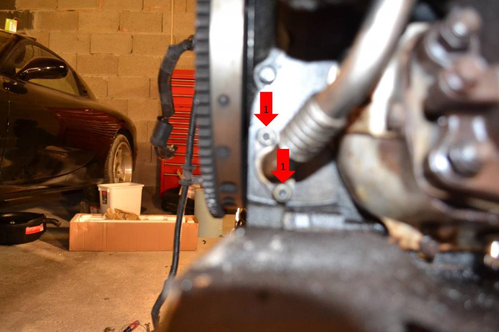
1: Remove these two bolts above the OMP.
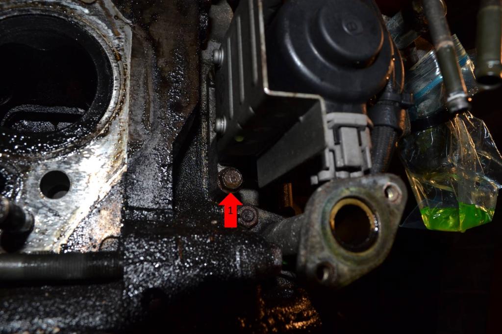
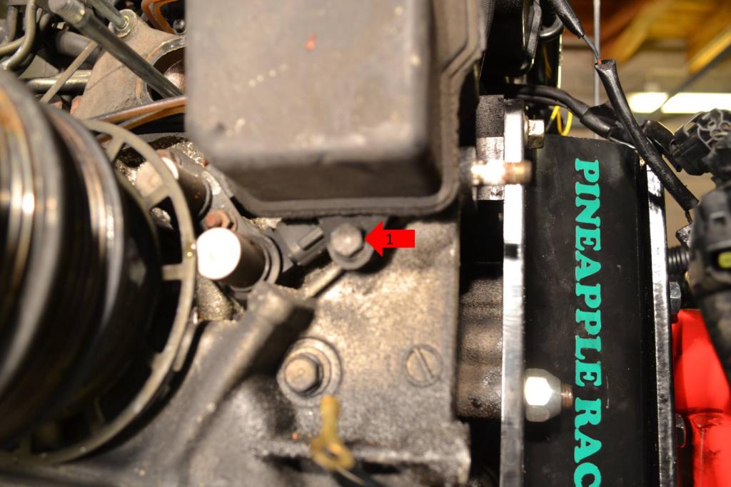
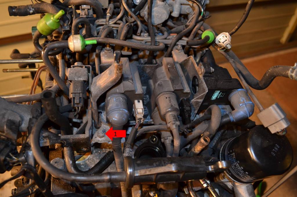
1: Remove this bolt under the OMP.
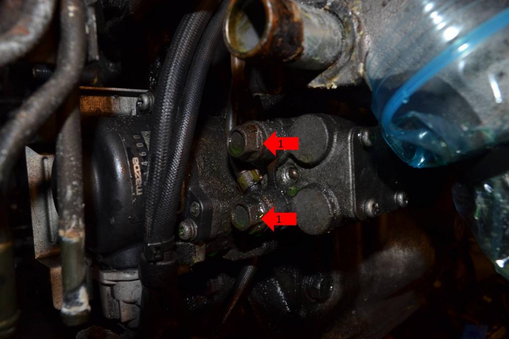
1: Remove the two banjo bolts and remove the lines. You can then put the banjo bolts back where they were on the pump.
OMP removal will continue on the next post.
1: Remove the two bolts securing the rear oil return.

1: Remove these three nuts.
2: Remove these two bolts.

1: Remove these three nuts. The entire turbo assembly is now free and can be set aside.

Now to remove the exhaust manifold.
1: Remove this bolt on the heat shield.

1: Remove this bolt on the heat shield.

1: Remove the clip securing the actuator rod.
2: Remove these two bolts securing the actuator and the last nut securing the heat shield. Both the actuator and heat shield can be set aside.

1: Remove these two nuts.

1: Remove these two nuts. The exhaust manifold will now come off and can be set aside.

Now remove both motor mounts.
1: Remove all six bolts. There are three on each mount. Once removed, the mounts can be set aside.

Alright, move on to the Oil Metering Pump (OMP) now.
1: Remove these two bolts above the OMP.

1: Remove this bolt under the OMP.

1: Remove the two banjo bolts and remove the lines. You can then put the banjo bolts back where they were on the pump.

OMP removal will continue on the next post.
Thread Starter
Full Member
Joined: Jan 2015
Posts: 59
Likes: 2
From: K-Town, Germany
Season 2 - Episode 1 Continued
Continuing with the removal of the OMP.
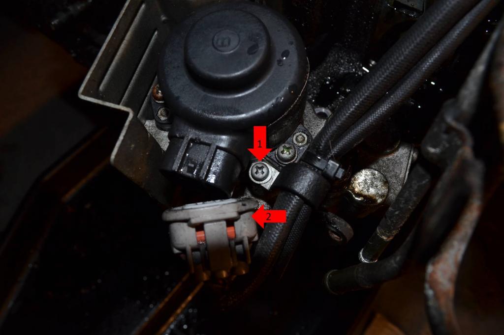
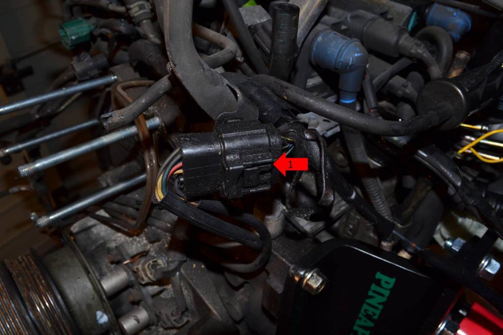
1: Remove this screw that secures the OMP wiring.
2: Remove this plug. It's easier to do once the OMP is free. You can see it's already been unplugged in the pic.
1: Remove these two screws. The pump will now be free and can be set aside.
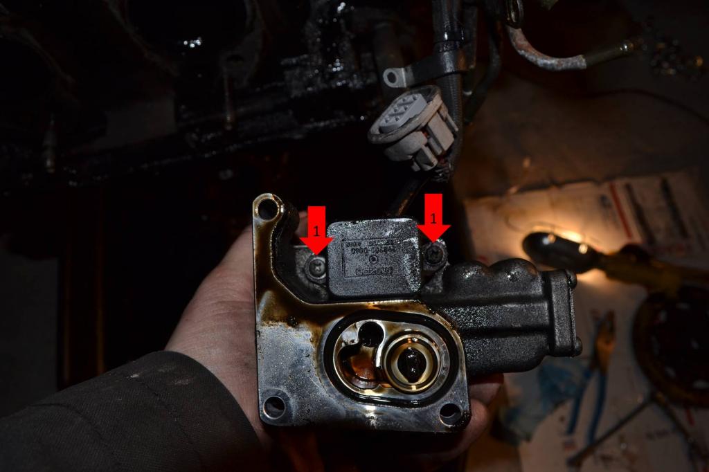
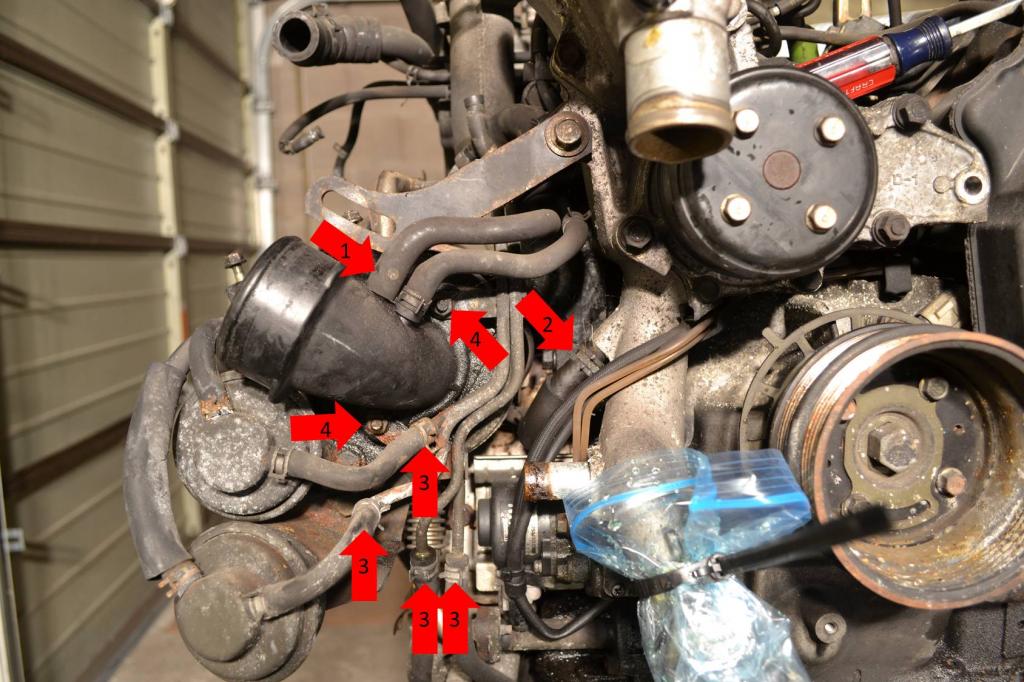
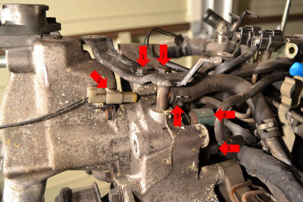
Now to remove the water pump. And entire housing.
1: Remove the two bolts securing this bracket. This just makes it easier for you to access a line and two plugs.
2: Unplug this.
3: Remove this line.
4: Unplug this sensor.
5: Unplug this sensor as well. It's very hard to see and is actually easier to unplug once the entire pump is coming off the engine. But if you can get it now, go ahead.
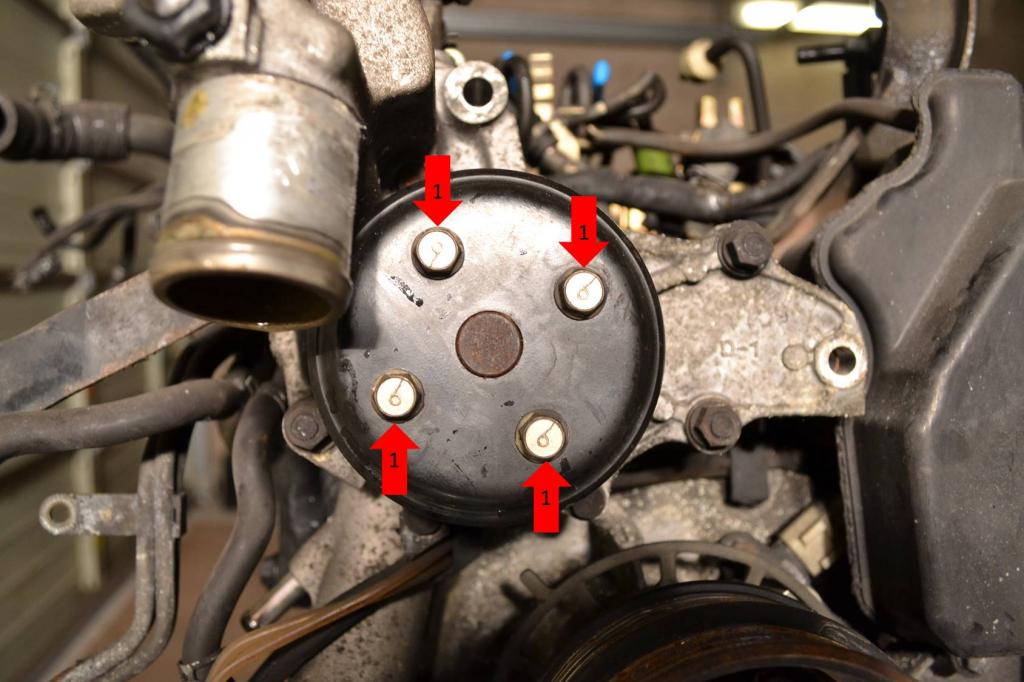
1: Remove the 4 bolts securing the pulley.
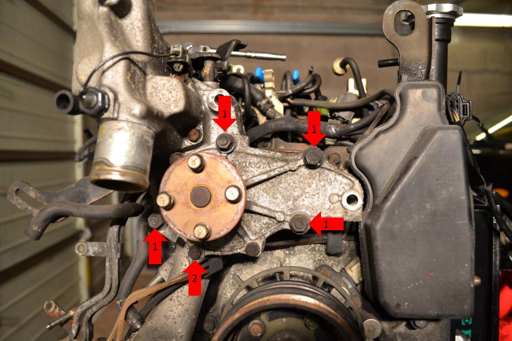
1: Remove the four nuts that hold the pump and housing to the engine.
2: Remove this bolt and remove the bracket. This bracket holds the lines and wiring for the OMP you removed earlier.
At this point the water pump and housing can be removed and set aside.
Once that is done, remove the oil filler neck and vacuum canister.
1: Remove this hose from the oil filler neck.
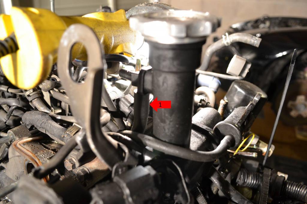
1: Remove these two bolts from the base of the neck.
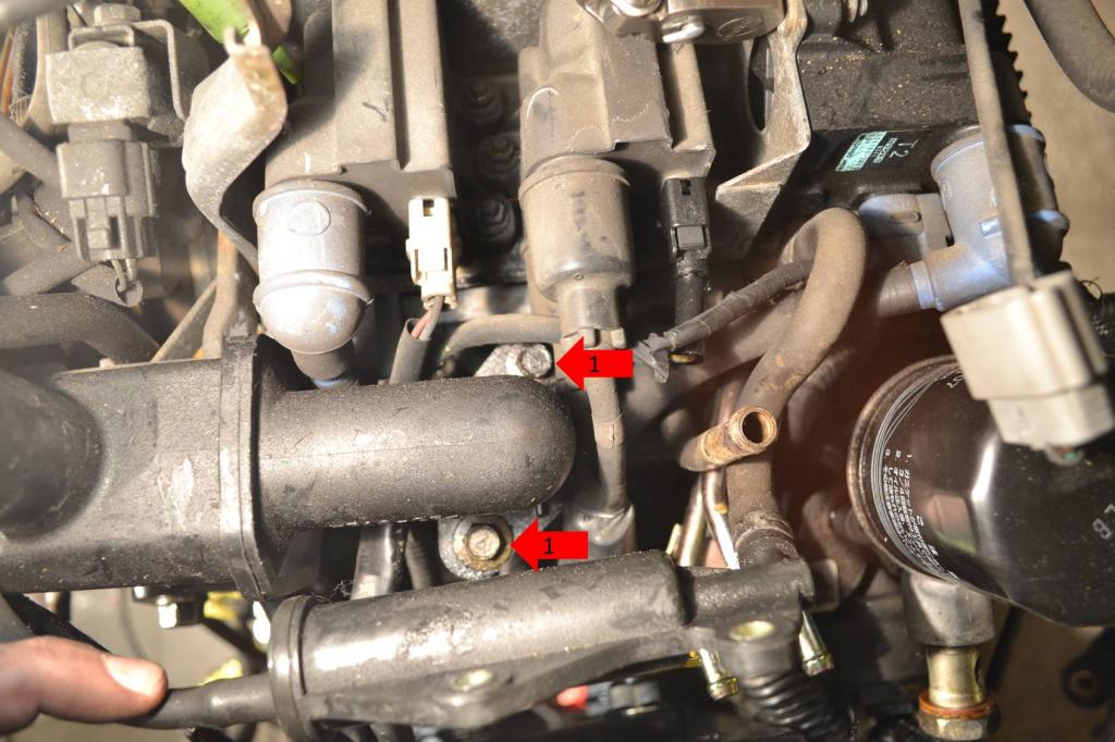
1: Remove this bolt from under the neck. The oil filler neck can now be set aside.
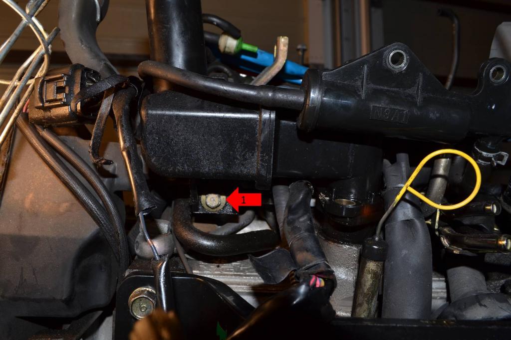
Now the vacuum canister.
1: Remove this vacuum line.
1: Remove this bolt on the side of the canister.
1: Remove this bolt under the canister. The canister can now be set aside.
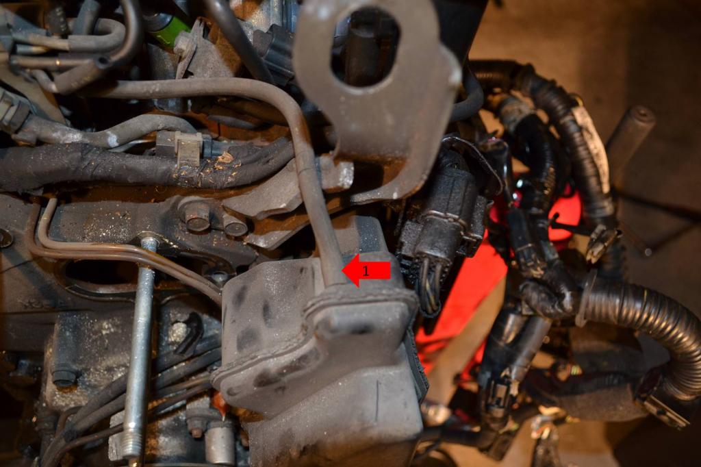
At this point it was pretty easy for me to remove one of the wiring harnesses. It's the harness that has both the battery terminals on it.
1: Remove this plug mounted to the engine lift bracket.
The wire harness removal will finish next post.
1: Remove this screw that secures the OMP wiring.
2: Remove this plug. It's easier to do once the OMP is free. You can see it's already been unplugged in the pic.

1: Remove these two screws. The pump will now be free and can be set aside.

Now to remove the water pump. And entire housing.
1: Remove the two bolts securing this bracket. This just makes it easier for you to access a line and two plugs.
2: Unplug this.
3: Remove this line.
4: Unplug this sensor.
5: Unplug this sensor as well. It's very hard to see and is actually easier to unplug once the entire pump is coming off the engine. But if you can get it now, go ahead.

1: Remove the 4 bolts securing the pulley.

1: Remove the four nuts that hold the pump and housing to the engine.
2: Remove this bolt and remove the bracket. This bracket holds the lines and wiring for the OMP you removed earlier.
At this point the water pump and housing can be removed and set aside.

Once that is done, remove the oil filler neck and vacuum canister.
1: Remove this hose from the oil filler neck.

1: Remove these two bolts from the base of the neck.

1: Remove this bolt from under the neck. The oil filler neck can now be set aside.

Now the vacuum canister.
1: Remove this vacuum line.

1: Remove this bolt on the side of the canister.

1: Remove this bolt under the canister. The canister can now be set aside.

At this point it was pretty easy for me to remove one of the wiring harnesses. It's the harness that has both the battery terminals on it.
1: Remove this plug mounted to the engine lift bracket.

The wire harness removal will finish next post.
Thread Starter
Full Member
Joined: Jan 2015
Posts: 59
Likes: 2
From: K-Town, Germany
Season 2 - Episode 1 Continued
Finishing up the wire harness removal.
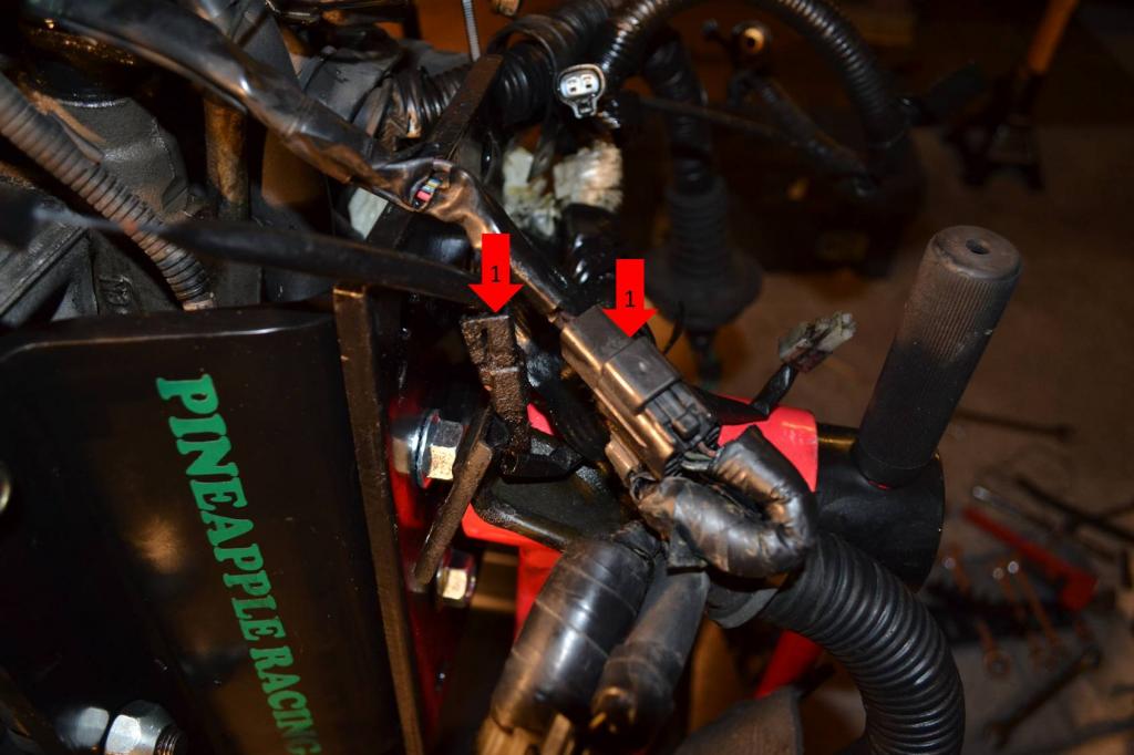
1: Remove these two plugs. There is actually a third plug, but it was buried and I couldn't get a picture of it. It's the only other plug now attaching the wiring harness to the engine. Just unplug it and set the harness aside.
Removing that harness actually unplugs the entire coil pack assembly. So we'll move onto pulling that off next. Unplug all of the spark plug wires from the spark plugs, they can come off with the coil pack assembly.
1: Remove these three nuts.
1: Remove this nut. The entire assembly will now lift out, set it aside.
After the coils are out, we can move on to the worst part. The stupid *** rat's nest. I tried to get pictures of everything, and will try to remember everything I did to post here. But, I may be forgetting a thing or two.
1: Pull these three bolts out. These are the only bolts actually holding the rat's nest in. I think they do less to hold the nest in than all of vacuum lines. lol
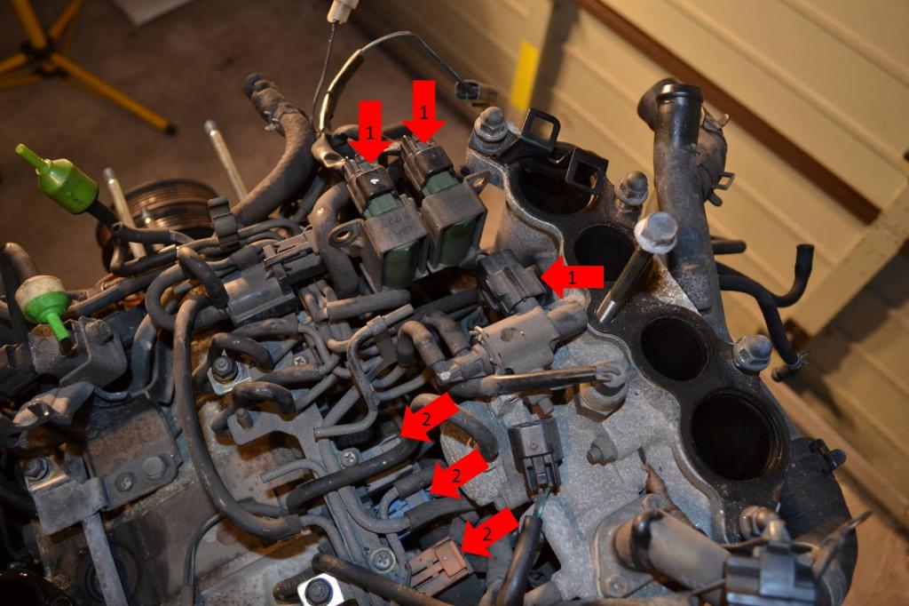
1: Remove all of these plugs.
2: Remove these three plugs. There are actually three more, in the same layout, towards the front of the engine underneath the rat's nest. You can't really see them in the picture, but they're there. The easiest way to remove them is to wait until the nest is loose and coming out, you can access them easier at that point than you can now.
1: Remove these two lines.
2: Follow this line around to the fuel pulse regulator and remove it.
1: Remove the fuel lines.
1: Remove this line. This will actually let the entire hard-line assembly you removed from the turbo earlier come free.
1: Remove these five hoses. At this point, my rat's next came out.
Next post will begin with the removal of the main engine harness.
1: Remove these two plugs. There is actually a third plug, but it was buried and I couldn't get a picture of it. It's the only other plug now attaching the wiring harness to the engine. Just unplug it and set the harness aside.

Removing that harness actually unplugs the entire coil pack assembly. So we'll move onto pulling that off next. Unplug all of the spark plug wires from the spark plugs, they can come off with the coil pack assembly.
1: Remove these three nuts.

1: Remove this nut. The entire assembly will now lift out, set it aside.

After the coils are out, we can move on to the worst part. The stupid *** rat's nest. I tried to get pictures of everything, and will try to remember everything I did to post here. But, I may be forgetting a thing or two.
1: Pull these three bolts out. These are the only bolts actually holding the rat's nest in. I think they do less to hold the nest in than all of vacuum lines. lol

1: Remove all of these plugs.
2: Remove these three plugs. There are actually three more, in the same layout, towards the front of the engine underneath the rat's nest. You can't really see them in the picture, but they're there. The easiest way to remove them is to wait until the nest is loose and coming out, you can access them easier at that point than you can now.

1: Remove these two lines.
2: Follow this line around to the fuel pulse regulator and remove it.

1: Remove the fuel lines.

1: Remove this line. This will actually let the entire hard-line assembly you removed from the turbo earlier come free.

1: Remove these five hoses. At this point, my rat's next came out.

Next post will begin with the removal of the main engine harness.
Thread Starter
Full Member
Joined: Jan 2015
Posts: 59
Likes: 2
From: K-Town, Germany
Season 2 - Episode 1 Continued
Alright, now that the rat's nest is out, we can remove the main engine harness and the lower intake manifold (LIM)
1: Unplug all of these connectors.
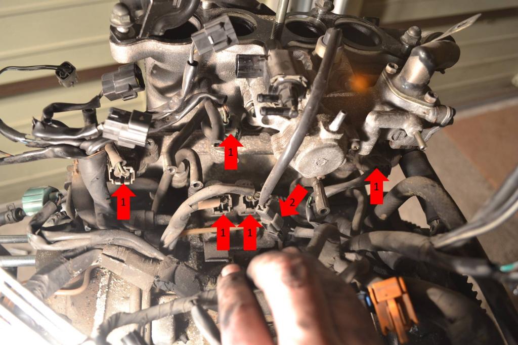
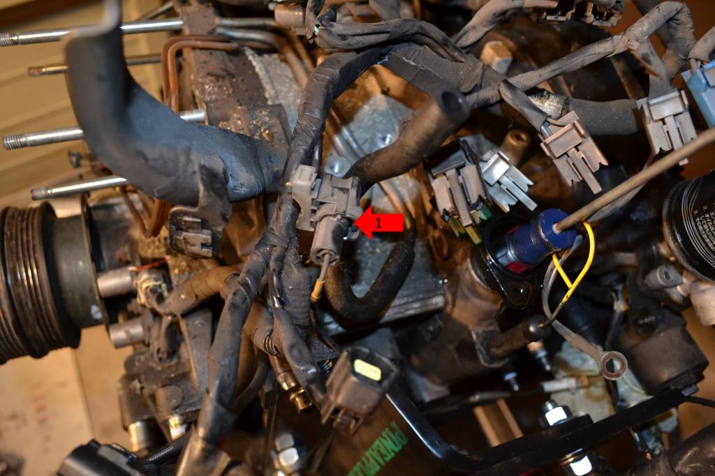
1: Remove this plug.
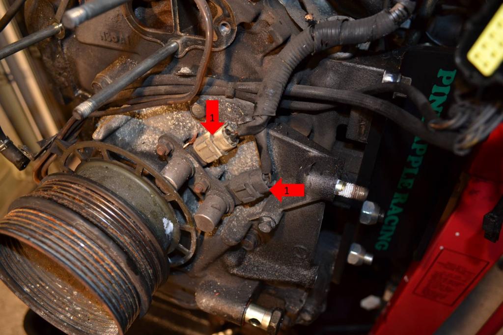
1: Remove both of these plugs.
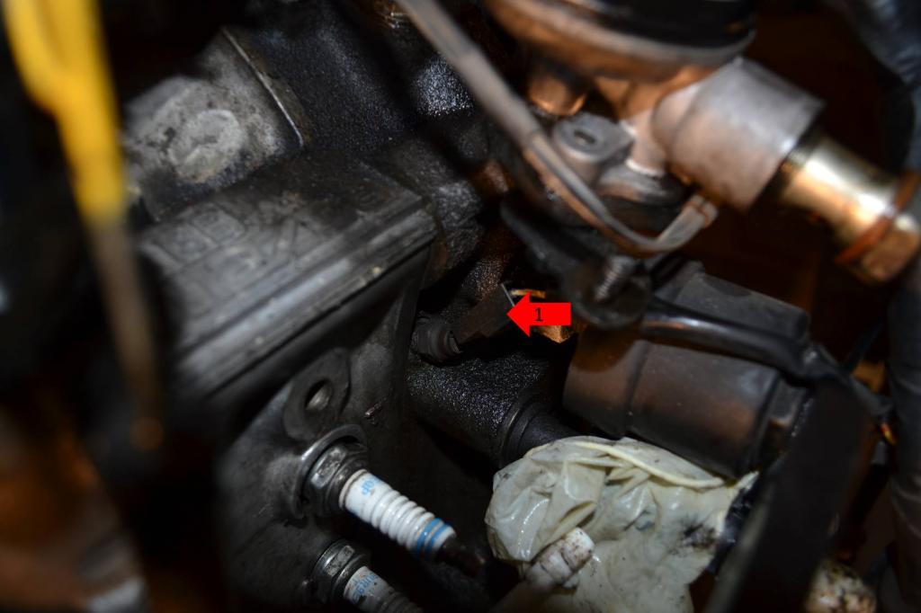
1: Finally, remove this plug on the sensor just below the oil filter housing. The entire harness will now be free and can be set aside.
Removing the LIM is super easy.
1: Remove this hose.
2: Remove these five bolts and two nuts. The LIM is now free and can be set aside.
Next remove the turbo oil feed, injectors, and oil injectors.
1: Remove this banjo bolt. The turbo's oil feed can now be removed and set aside.
1: Remove these two bolts and the injectors can be removed and set aside.
1: Remove both of these vacuum lines and then the injectors themselves. They can be set aside, as well as the lines and wiring that went to the OMP.
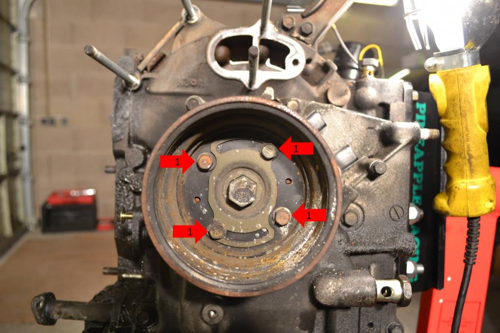
Now to get the pulleys off the front of the eccentric shaft.
1: Remove these four bolts and the pulleys will come off. Set them aside.
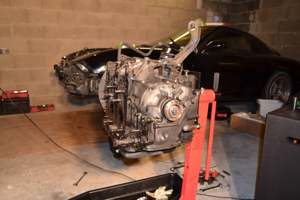
This is where I stopped working yesterday. And here's what the engine looked like at this point.
1: Unplug all of these connectors.

1: Remove this plug.

1: Remove both of these plugs.

1: Finally, remove this plug on the sensor just below the oil filter housing. The entire harness will now be free and can be set aside.

Removing the LIM is super easy.
1: Remove this hose.

2: Remove these five bolts and two nuts. The LIM is now free and can be set aside.

Next remove the turbo oil feed, injectors, and oil injectors.
1: Remove this banjo bolt. The turbo's oil feed can now be removed and set aside.

1: Remove these two bolts and the injectors can be removed and set aside.

1: Remove both of these vacuum lines and then the injectors themselves. They can be set aside, as well as the lines and wiring that went to the OMP.

Now to get the pulleys off the front of the eccentric shaft.
1: Remove these four bolts and the pulleys will come off. Set them aside.

This is where I stopped working yesterday. And here's what the engine looked like at this point.

Thread Starter
Full Member
Joined: Jan 2015
Posts: 59
Likes: 2
From: K-Town, Germany
Season 2 - Episode 2
I know all of the Season 2 - Episode 1 posts were made like an hour ago. But, those contained the work I did yesterday. This post, and the next post, will contain all the work I did today. This will basically cover the removal of everything external to the engine.
Start with removing the oil filter housing, oil pressure sender, coolant line adapter, and sensor.
1: Remove these two nuts and set the oil filter housing aside.
2: Remove the sender.
3: Remove this coolant hose adapter.
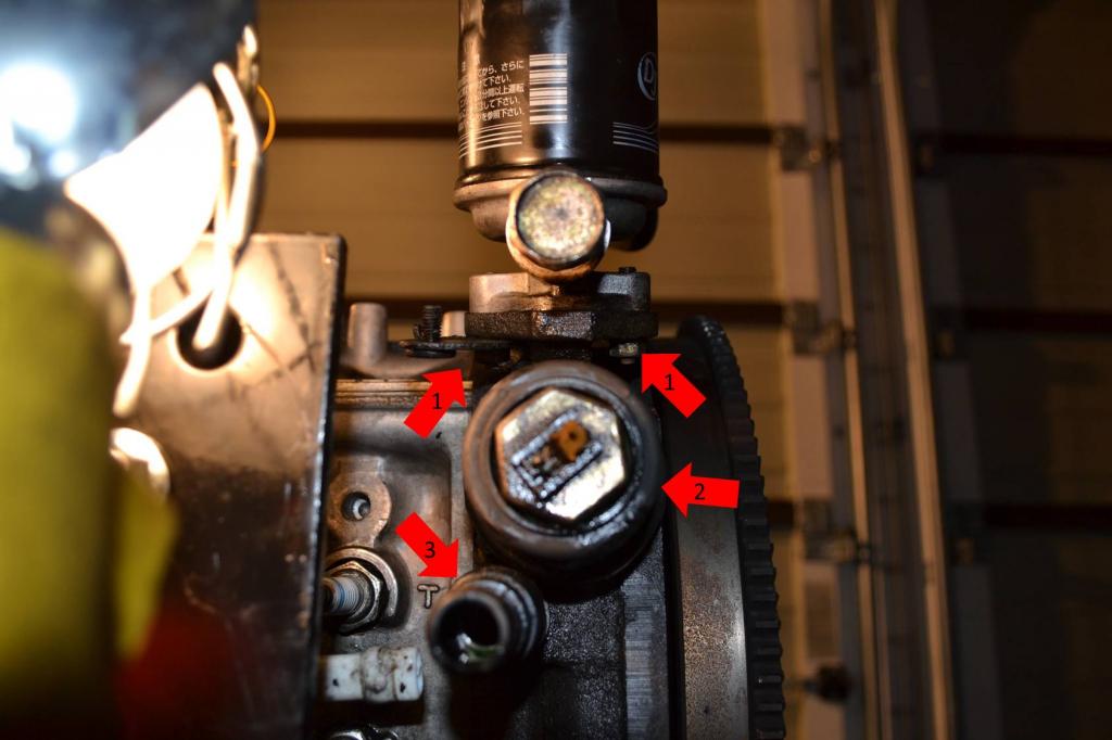
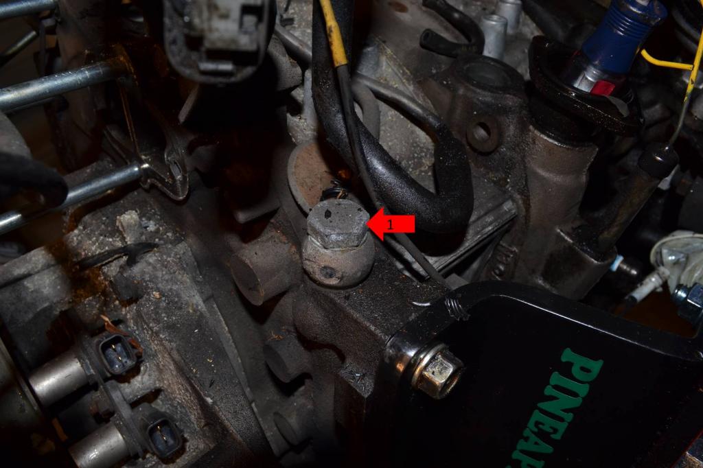
1: Remove this sensor.
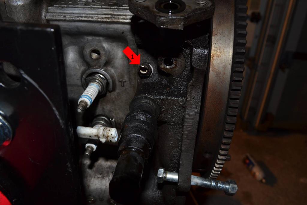
1: Remove the knock sensor.
1: Remove these two bolts to remove the engine hoist bracket.
1: Remove these two nuts to remove the rest of the front turbo oil return.
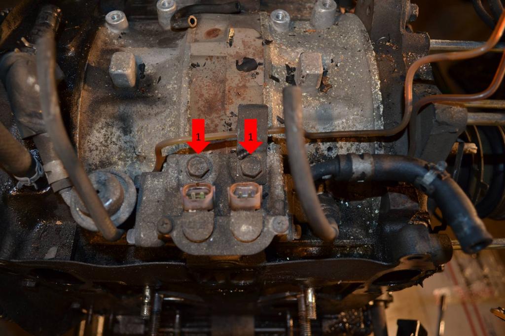
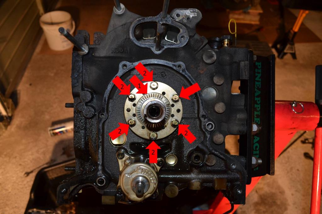
1: Remove these two nuts and remove the two sensors.
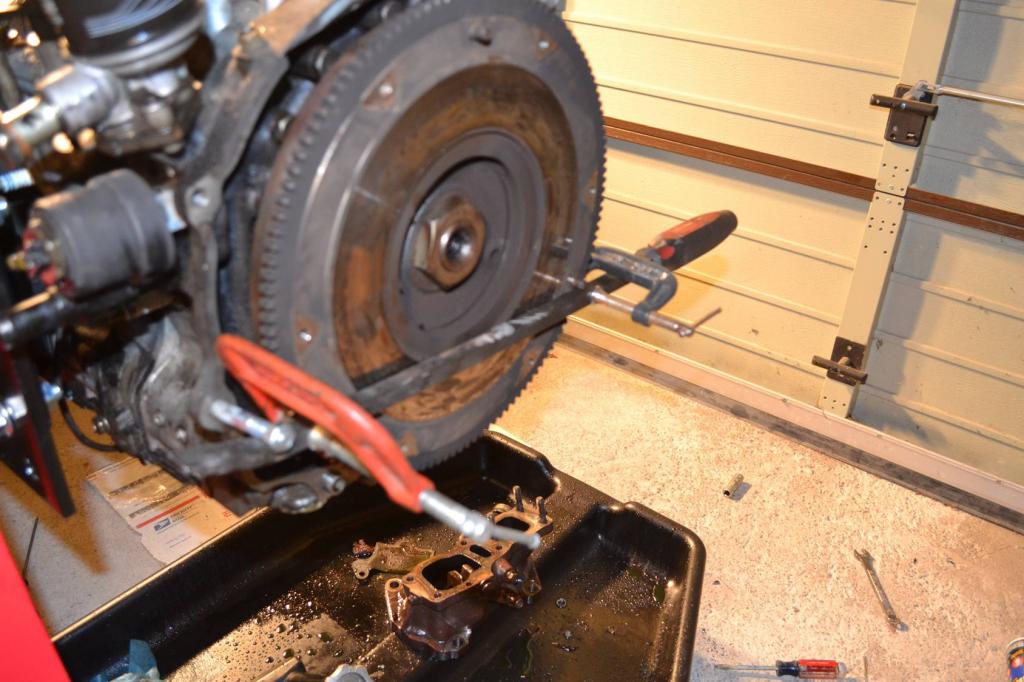
2: Remove the large center bolt. You will have to lock the flywheel in place. The next picture shows how I did it. Also, heating the bolt and using a large breaker bar makes the job a lot easier. Once the bolt is out, the pulley adapter will come off.
This is how I locked the flywheel. Pretty ghetto, but it worked. The C-clamps kept the pry bar from popping out of place. The pry bar was up against the dowels on the flywheel and the bolt you see is what kept it from spinning.
Remove the oil pan next.
1: Remove these bolts. I'm not marking/showing all of the bolts, because that would take forever. Just follow the trail of bolts around the pan and remove them all. I think there were 17, but I don't remember for sure.
Then use a scraper to slide between the ban and engine. Work it all the way around. This will save the pan. Where as prying on it like a tard-monkey will **** it up.
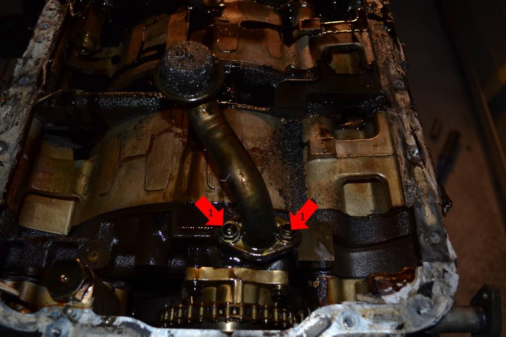
Once the pan is off, remove the sump.
1: Remove these two bolts and the sump will come off. Set it aside.
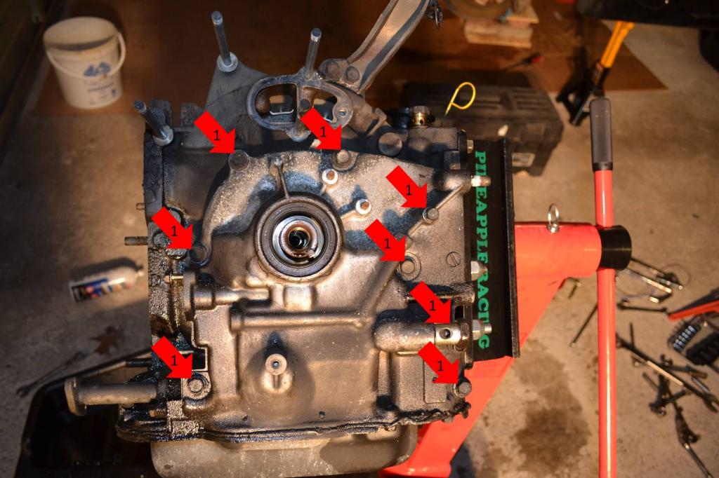
Now remove the front case. I know the pan is still on in the picture, that's just the order I photographed it. However, when I pulled the case off, the pan was already off.
1: Remove all of these bolts and the case will lift off, one of them is hiding under the banjo bolt, but it's there. Set the case aside.
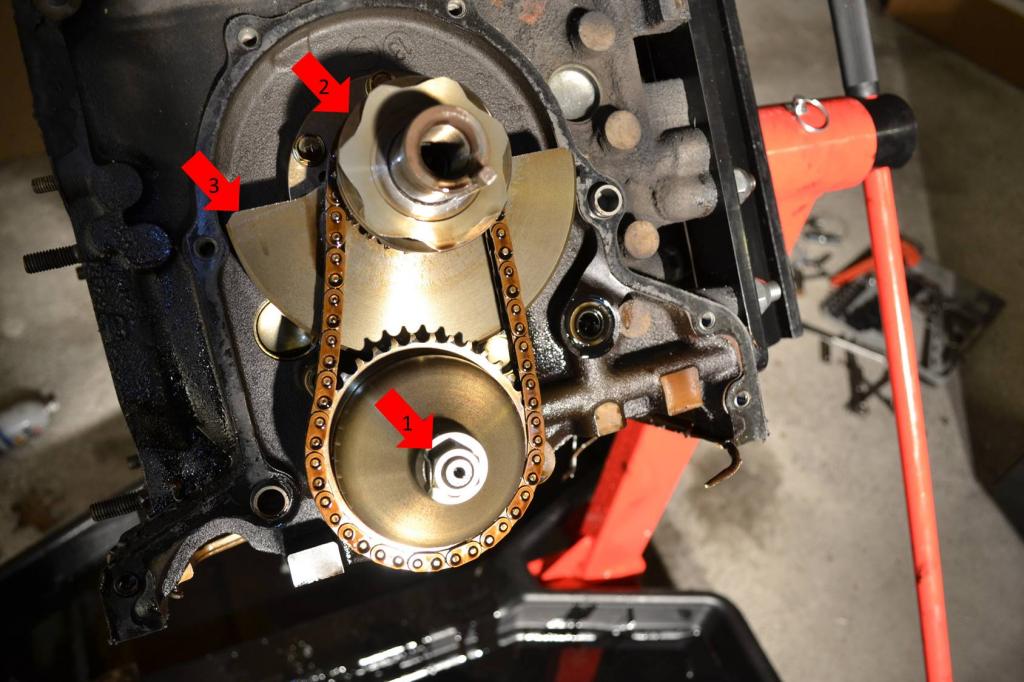
Once the case is off. The oil pump, sprockets, and chain will be exposed.
1: Remove this nut. You will have to use a chisel and bend the washer straight. Keep the nut close by, cause you need to put it back on the shaft immediately after removing the sprocket.
2: As you lift the sprocket of the oil pump, you will have to lift this sprocket as well. The sprockets and chain will come off together. Make sure you get the woodruff keys off both shafts as well and save them. Set all of this stuff aside.
The next post will start with the torrington bearing and thrust plate removal and the oil pump removal.
Start with removing the oil filter housing, oil pressure sender, coolant line adapter, and sensor.
1: Remove these two nuts and set the oil filter housing aside.
2: Remove the sender.
3: Remove this coolant hose adapter.

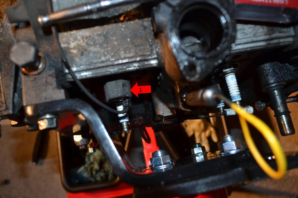
1: Remove this sensor.

1: Remove the knock sensor.

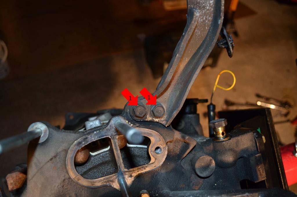
1: Remove these two bolts to remove the engine hoist bracket.

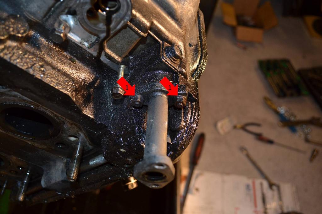
1: Remove these two nuts to remove the rest of the front turbo oil return.

1: Remove these two nuts and remove the two sensors.
2: Remove the large center bolt. You will have to lock the flywheel in place. The next picture shows how I did it. Also, heating the bolt and using a large breaker bar makes the job a lot easier. Once the bolt is out, the pulley adapter will come off.

This is how I locked the flywheel. Pretty ghetto, but it worked. The C-clamps kept the pry bar from popping out of place. The pry bar was up against the dowels on the flywheel and the bolt you see is what kept it from spinning.

Remove the oil pan next.
1: Remove these bolts. I'm not marking/showing all of the bolts, because that would take forever. Just follow the trail of bolts around the pan and remove them all. I think there were 17, but I don't remember for sure.

Then use a scraper to slide between the ban and engine. Work it all the way around. This will save the pan. Where as prying on it like a tard-monkey will **** it up.

Once the pan is off, remove the sump.
1: Remove these two bolts and the sump will come off. Set it aside.

Now remove the front case. I know the pan is still on in the picture, that's just the order I photographed it. However, when I pulled the case off, the pan was already off.
1: Remove all of these bolts and the case will lift off, one of them is hiding under the banjo bolt, but it's there. Set the case aside.

Once the case is off. The oil pump, sprockets, and chain will be exposed.
1: Remove this nut. You will have to use a chisel and bend the washer straight. Keep the nut close by, cause you need to put it back on the shaft immediately after removing the sprocket.
2: As you lift the sprocket of the oil pump, you will have to lift this sprocket as well. The sprockets and chain will come off together. Make sure you get the woodruff keys off both shafts as well and save them. Set all of this stuff aside.

The next post will start with the torrington bearing and thrust plate removal and the oil pump removal.
Thread Starter
Full Member
Joined: Jan 2015
Posts: 59
Likes: 2
From: K-Town, Germany
Season 2 - Episode 2 Continued
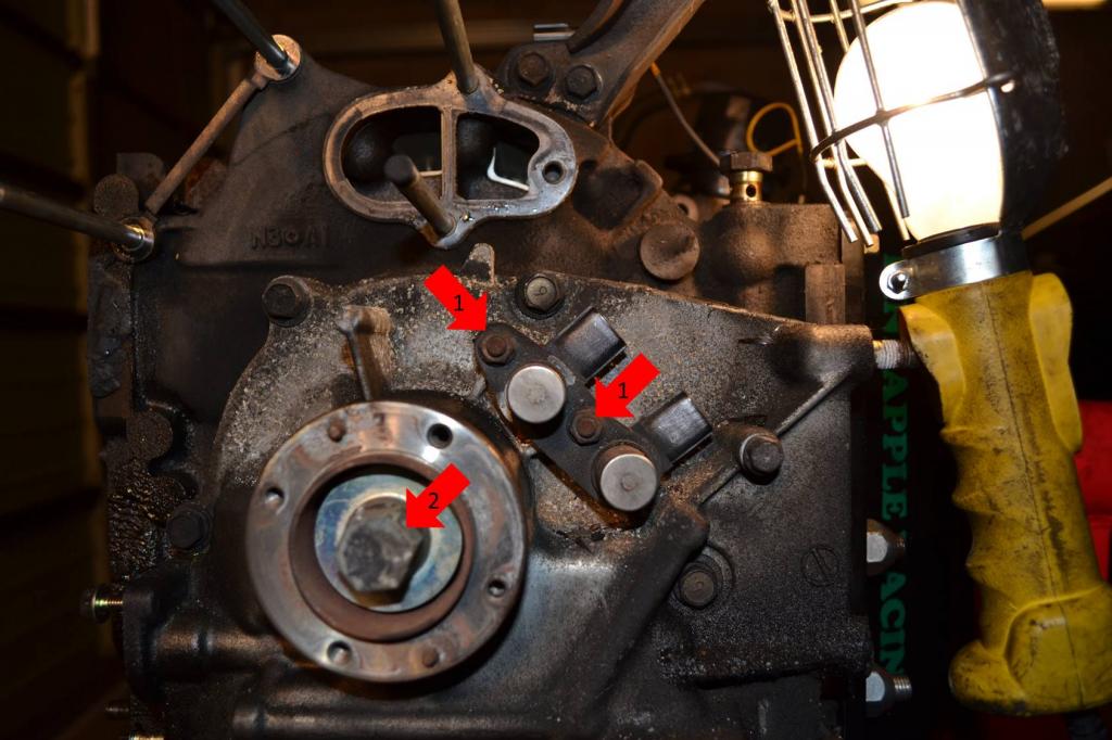
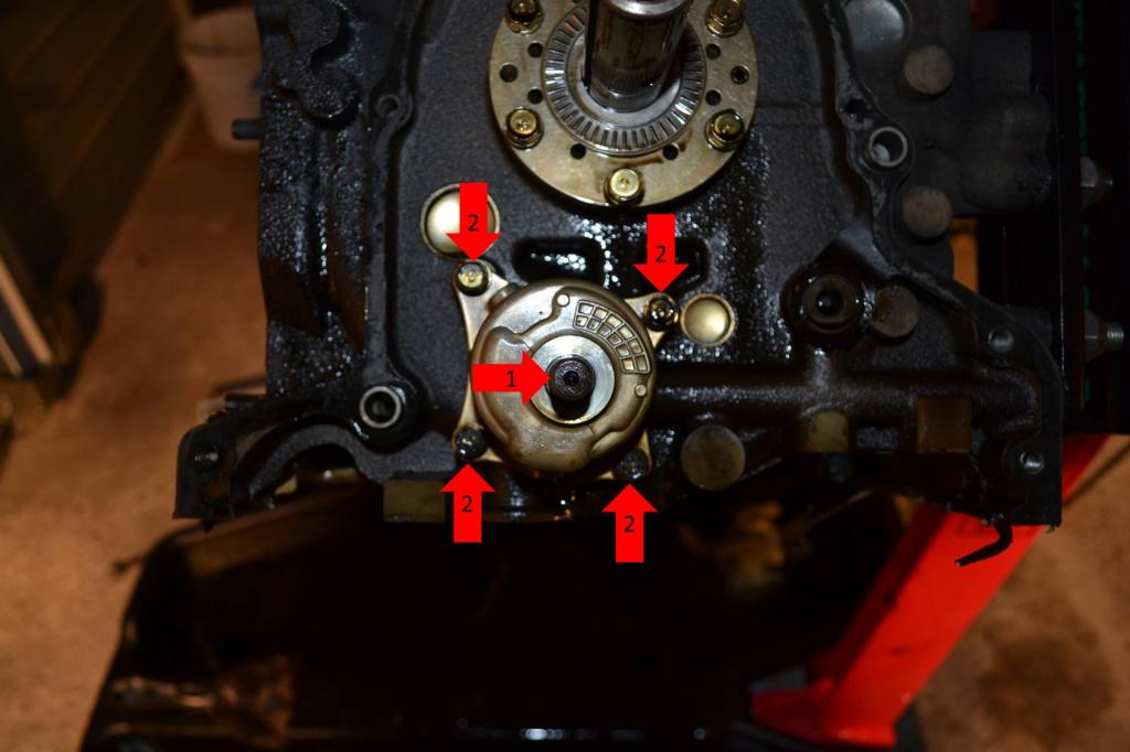
1: Remove the outer torrington bearing.
2: Remove the six bolts securing the thrust plate. There will be another torrington bearing behind it. Remove it as well.
1: Before you remove the oil pump you need to put the nut back on the shaft. This will keep the oil pump from coming apart when you remove it. It's not on in this picture. But it was when I removed the pump.
2: Remove the four bolts securing the oil pump. The pump will now come off and can be set aside.
Well that's all out of the way. Just a couple more things.
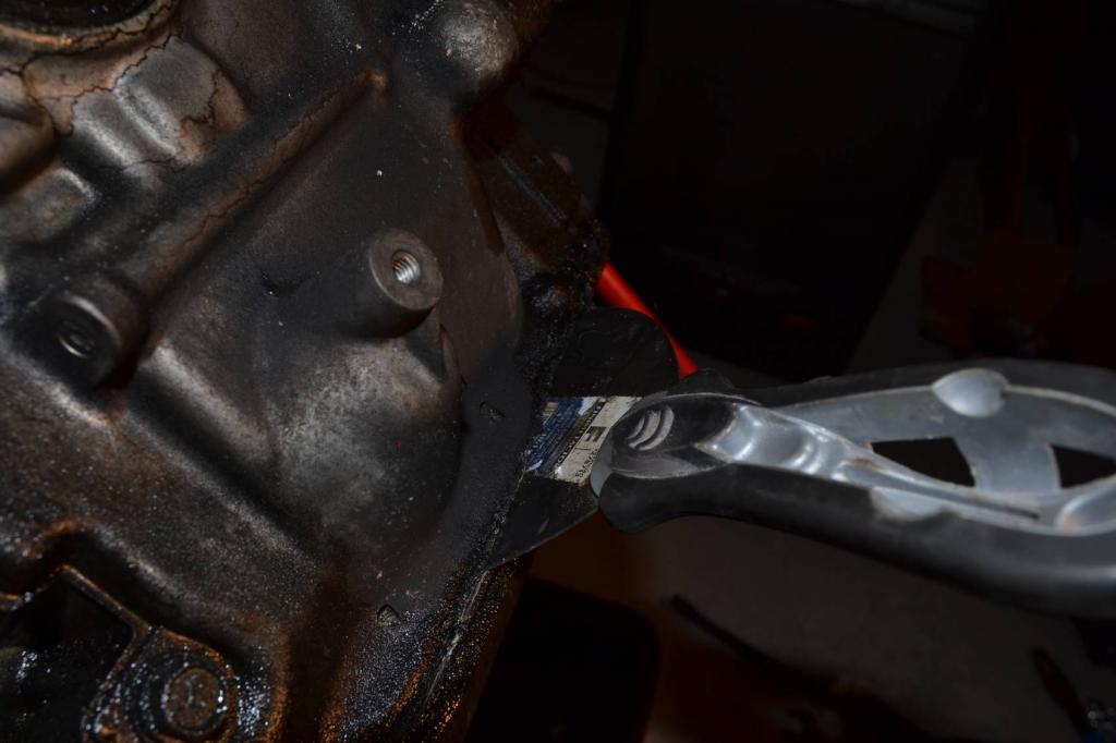
1: Remove the four water pump studs. Just use a pair of vice-grips, makes it super simple.
1: Remove the two bolts securing this dust shield next to the flywheel and set the shield aside.
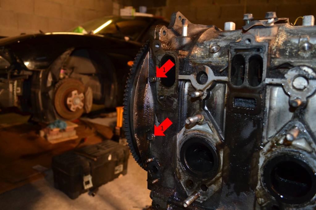
And there she is. The engine is basically completely bare.
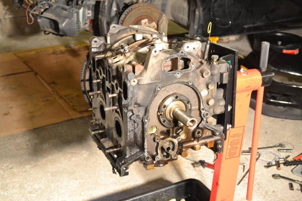
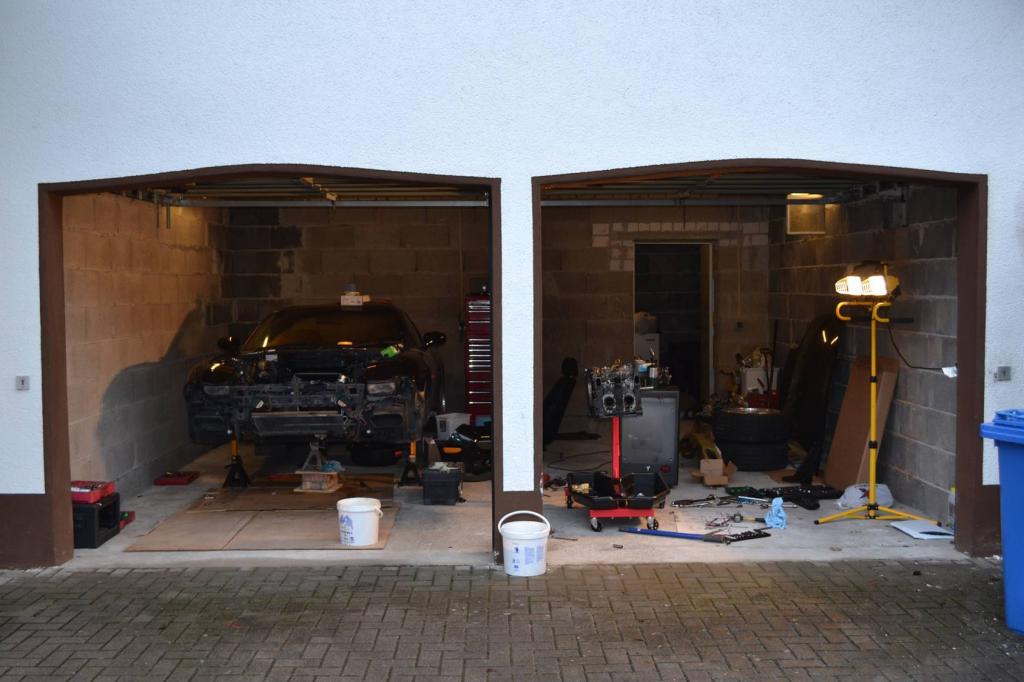
The garage is looking pretty rough at this point. I really need to clean it up and organize everything.
Anyways, the motor is now completely bare, well for the most part. The flywheel is still on it because I haven't received my 54mm socket yet. So I can't remove the nut on it.
The next episode will be when I actually open the engine up. I'm thinking that's going to be a while though. Hopefully not too long.
2: Remove the six bolts securing the thrust plate. There will be another torrington bearing behind it. Remove it as well.

1: Before you remove the oil pump you need to put the nut back on the shaft. This will keep the oil pump from coming apart when you remove it. It's not on in this picture. But it was when I removed the pump.
2: Remove the four bolts securing the oil pump. The pump will now come off and can be set aside.

Well that's all out of the way. Just a couple more things.
1: Remove the four water pump studs. Just use a pair of vice-grips, makes it super simple.

1: Remove the two bolts securing this dust shield next to the flywheel and set the shield aside.

And there she is. The engine is basically completely bare.

The garage is looking pretty rough at this point. I really need to clean it up and organize everything.

Anyways, the motor is now completely bare, well for the most part. The flywheel is still on it because I haven't received my 54mm socket yet. So I can't remove the nut on it.
The next episode will be when I actually open the engine up. I'm thinking that's going to be a while though. Hopefully not too long.
I can not say thank you enough for to work you have put into this. It is a lot of photos and time to document all of this.
I must say I could not be happier that my car is a single turbo and I dont have to deal with half of this crap!
I must say I could not be happier that my car is a single turbo and I dont have to deal with half of this crap!
Thread Starter
Full Member
Joined: Jan 2015
Posts: 59
Likes: 2
From: K-Town, Germany
I hope that when the car goes back together it's a single turbo and short a rat's nest. That should help out quite a bit.


Great job so far!
Few things to know -
- You don't have to remove the radiator/fans to remove the engine. It can just stay in place. If you do remove it, and the car will be outside for any length of time, you MUST bolt the relay box back in place. If it hangs upside down, water will run into the box and rust out the relays. I've seen this happen many times!
- You don't have to remove the hood, there's enough room to remove and reinstall it with the hood on.
- In the US, a Harbor Freight engine hoist has a long enough reach to use without having to remove the bumper. You can also rent hoists many times.
- I leave the PS pump on the bracket - just undo the one banjo bolt and one hose and one wire going to it. Bring it out with the engine, as well as the bracket. AC compressor stays in the car, 4 12mm bolts and it's off the bracket.
- The oil cooler lines have quick-disconnect fittings with clips, they're under the battery tray area. Just remove the horseshoe clips and pop the fittings out.
FYI, I can pull an engine and have it torn all the way down to the rotors and seals in 2 1/2 hours.
It also helps when you remove things from the engine as large components - the whole rat's nest, wiring harness, and fuel rails can all come off as one big piece, for example. Some things can just be left on the engine, like the front engine hanger - no reason to remove it. I also leave the oil filter and filter pedastal on the engine, makes it easy to grab the rear iron.
I'm glad you got the Pineapple engine stand adapter, that makes a MASSIVE difference in working on the engine. IMHO that's a must have for any engine project.
Keep up the good work!
Dale
Thread Starter
Full Member
Joined: Jan 2015
Posts: 59
Likes: 2
From: K-Town, Germany
Great job so far!
Few things to know -
- You don't have to remove the radiator/fans to remove the engine. It can just stay in place. If you do remove it, and the car will be outside for any length of time, you MUST bolt the relay box back in place. If it hangs upside down, water will run into the box and rust out the relays. I've seen this happen many times!
- You don't have to remove the hood, there's enough room to remove and reinstall it with the hood on.
- In the US, a Harbor Freight engine hoist has a long enough reach to use without having to remove the bumper. You can also rent hoists many times.
- I leave the PS pump on the bracket - just undo the one banjo bolt and one hose and one wire going to it. Bring it out with the engine, as well as the bracket. AC compressor stays in the car, 4 12mm bolts and it's off the bracket.
- The oil cooler lines have quick-disconnect fittings with clips, they're under the battery tray area. Just remove the horseshoe clips and pop the fittings out.
FYI, I can pull an engine and have it torn all the way down to the rotors and seals in 2 1/2 hours.
It also helps when you remove things from the engine as large components - the whole rat's nest, wiring harness, and fuel rails can all come off as one big piece, for example. Some things can just be left on the engine, like the front engine hanger - no reason to remove it. I also leave the oil filter and filter pedastal on the engine, makes it easy to grab the rear iron.
I'm glad you got the Pineapple engine stand adapter, that makes a MASSIVE difference in working on the engine. IMHO that's a must have for any engine project.
Keep up the good work!
Dale
Few things to know -
- You don't have to remove the radiator/fans to remove the engine. It can just stay in place. If you do remove it, and the car will be outside for any length of time, you MUST bolt the relay box back in place. If it hangs upside down, water will run into the box and rust out the relays. I've seen this happen many times!
- You don't have to remove the hood, there's enough room to remove and reinstall it with the hood on.
- In the US, a Harbor Freight engine hoist has a long enough reach to use without having to remove the bumper. You can also rent hoists many times.
- I leave the PS pump on the bracket - just undo the one banjo bolt and one hose and one wire going to it. Bring it out with the engine, as well as the bracket. AC compressor stays in the car, 4 12mm bolts and it's off the bracket.
- The oil cooler lines have quick-disconnect fittings with clips, they're under the battery tray area. Just remove the horseshoe clips and pop the fittings out.
FYI, I can pull an engine and have it torn all the way down to the rotors and seals in 2 1/2 hours.
It also helps when you remove things from the engine as large components - the whole rat's nest, wiring harness, and fuel rails can all come off as one big piece, for example. Some things can just be left on the engine, like the front engine hanger - no reason to remove it. I also leave the oil filter and filter pedastal on the engine, makes it easy to grab the rear iron.
I'm glad you got the Pineapple engine stand adapter, that makes a MASSIVE difference in working on the engine. IMHO that's a must have for any engine project.
Keep up the good work!
Dale
Admittedly, some of the things that I have done are not absolutely necessary. Things like removing the fans/radiator, power steering, and hood. I do those cause I consider it more convenient when they're out. But like you said, not necessary.
As for the engine hoist, I wish that I had mine with me. But I left it in the US, at my parent's house. My thinking was "I'll be in Germany for just 4 years, surely I won't be rebuilding any engines". lol. WRONG!!! 7 months into this assignment and here I am. I know that my hoist would have easily reached without removing the bumper. But not this one I'm using at the moment.
The Pineapple Racing bracket is awesome. I know people say they do the rebuilds without them, but I wanted to give the bracket a try. It's awesome to have.
Thread Starter
Full Member
Joined: Jan 2015
Posts: 59
Likes: 2
From: K-Town, Germany
Season 2 - Episode 3
Well, I actually got to rip apart the engine today. Basically all that I had to do was remove the flywheel and then pop the engine open.
All that holds the flywheel on is a 54mm nut. Just remove it and use a soft hammer on the edge of the flywheel to break it loose. My only hammer is steel, so I just used a piece of wood between the flywheel and hammer. It only took one hit to break the flywheel loose.
1: This is the nut you have to remove. Ignore my ghetto-*** flywheel lock, I set that up to get the front pulley off.

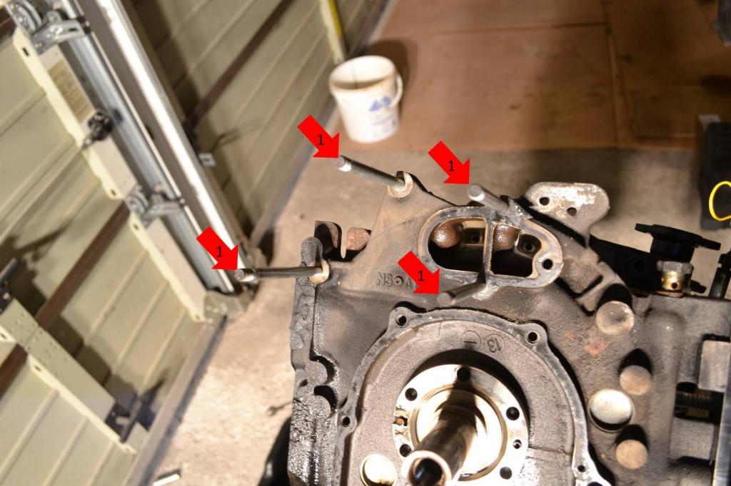
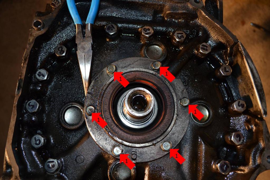
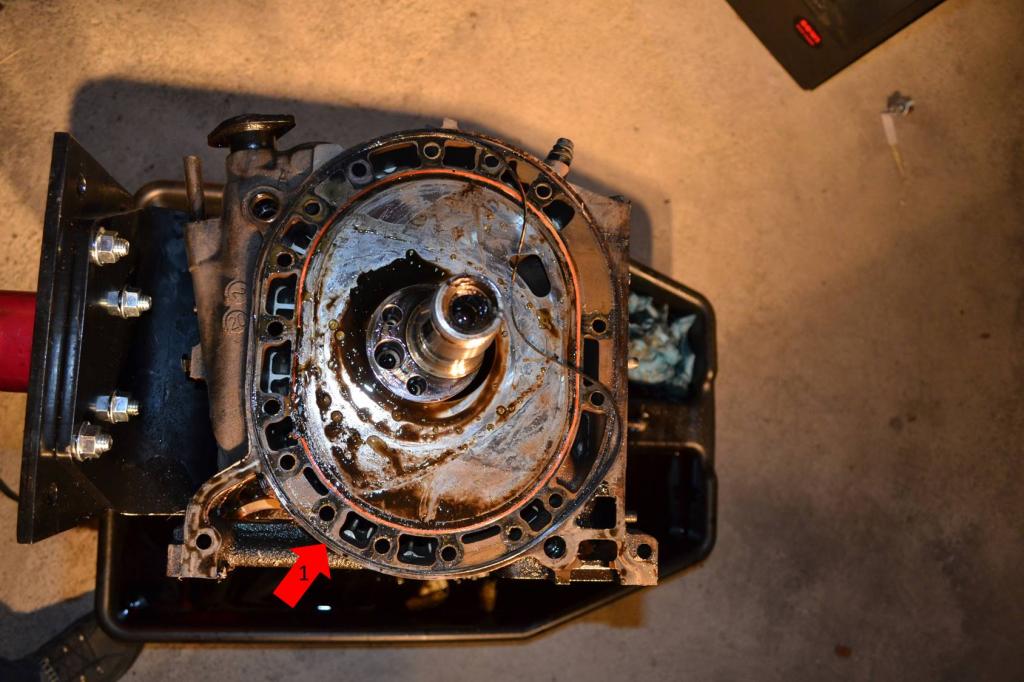
After the flywheel is off, remove the rear stationary gear.
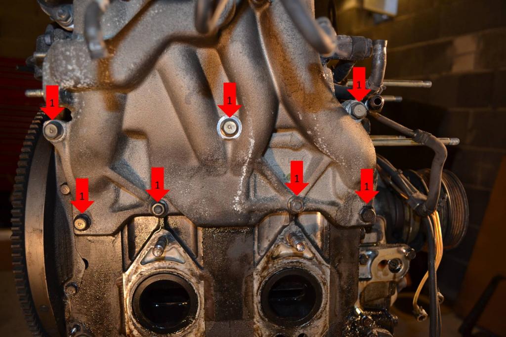
1: Remove these 6 bolts and them pop the gear out with a screwdriver or pry-bar.
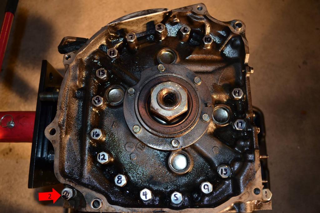
Now remove the bolts that hold the irons and housing together. The Factory Service Manual (FSM) from Mazda show the specific order the bolts need to be removed in. Also, the #2 bolt is a different length than the rest. This picture shows the bolts and their numbers written in sharpie. Just start with #1 (bottom right), and then follow the numbers in ascending order. Mazda recommends loosening them up progressively. I broke them loose, and then took them out on the second go 'round.
2: This is the #2 bolt. I couldn't write on it clearly, but it has a special stamp on it to identify it.
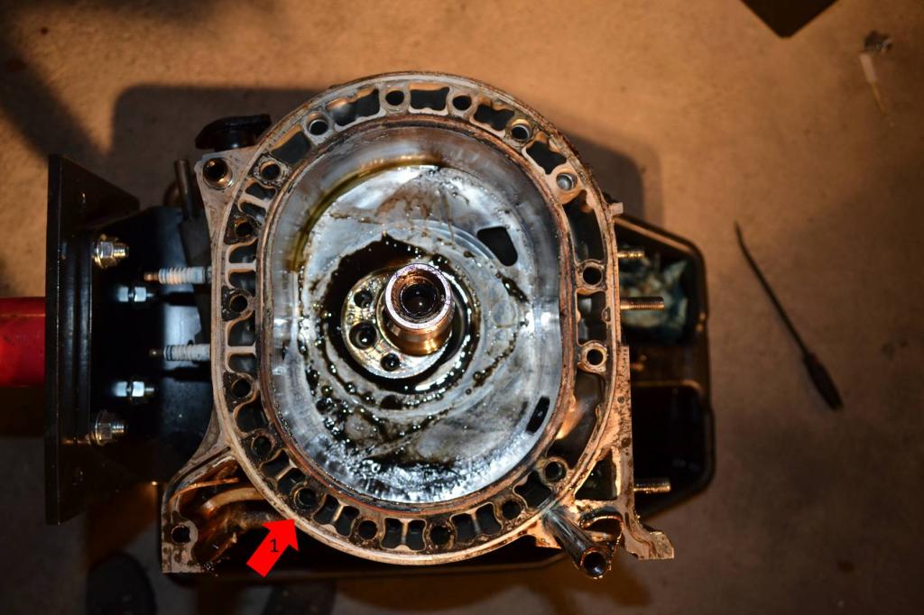
Once the bolts are all out you can remove the rear iron, and rear rotor. I didn't take any pictures of this. Just make sure that when you remove the rotors you keep all of the seals together with the rotor.
Next, remove the rear housing.
1: Remove this housing.
1: Remove the center iron and e-shaft. I probably didn't do this portion in the correct order. I just remove the center housing and pulled the e-shaft out with it. Then separated them once they were on the work bench.
1: Remove the front rotor.
2: Remove the front housing.
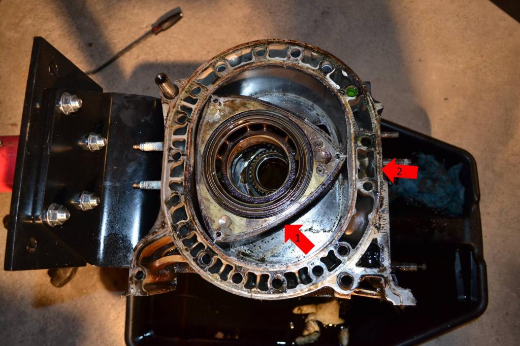
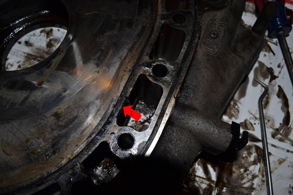
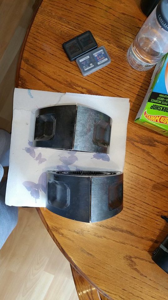
A this point, the engine is torn apart. Inspect all of the parts to determine what needs replacing. I already planned on replacing the oil, corner, apex, and side seals. But I discovered I would also have to replace the front and center iron, and more than likely the rear housing due to grooves in it. I will also need to replace the bearings in both the housings and both the rotors.
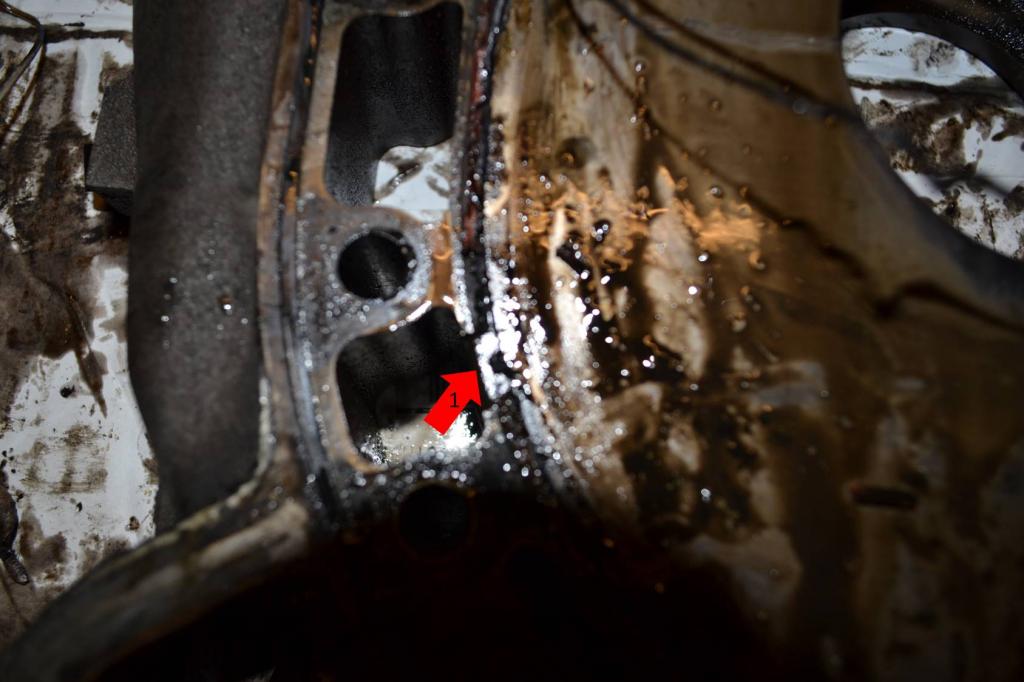
Here's the damage to the front housing.
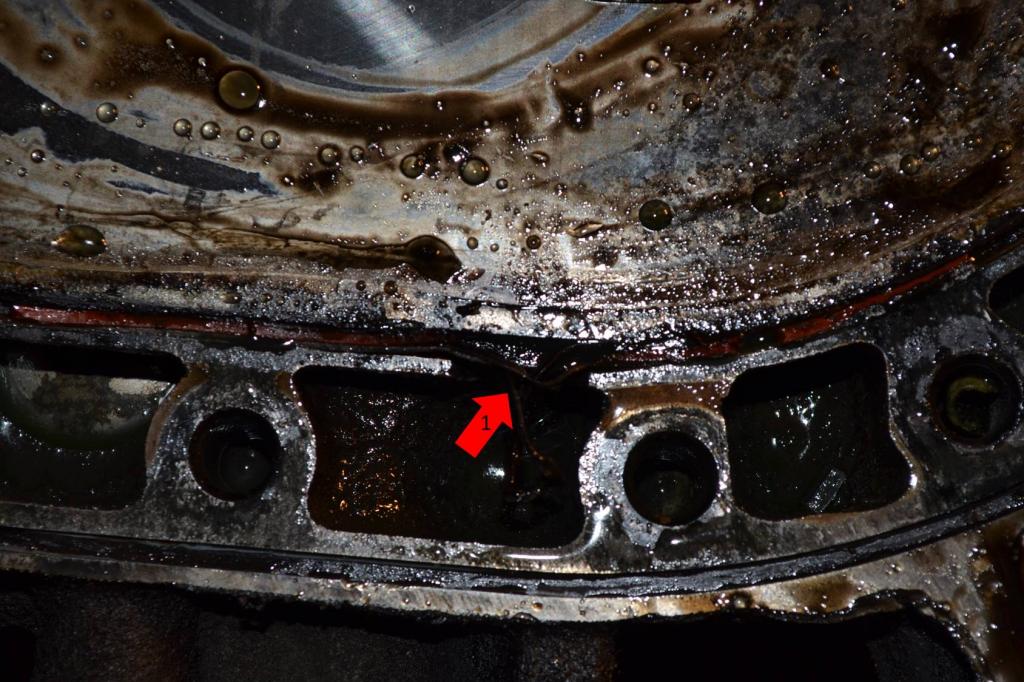
And the damage to the center housing. It's missing chunks on both sides.
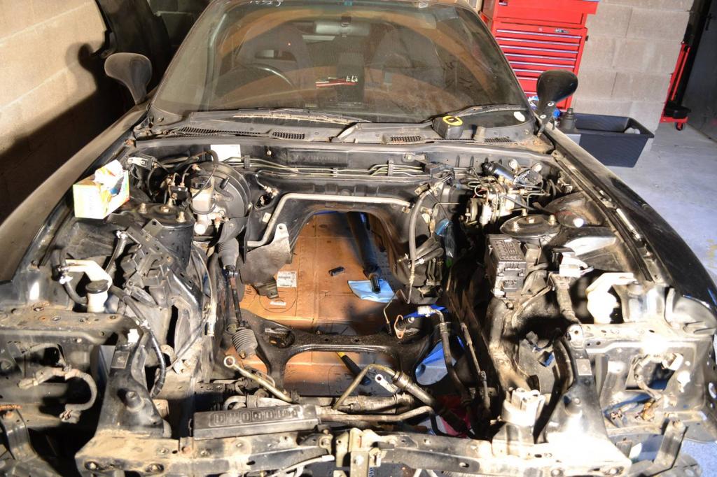
After I finished with the engine, me and my friend pulled the transmission and headlights. I'm working on stripping the engine bay, that way I can clean the car before it all goes back together.
Here's how she sits.
All that holds the flywheel on is a 54mm nut. Just remove it and use a soft hammer on the edge of the flywheel to break it loose. My only hammer is steel, so I just used a piece of wood between the flywheel and hammer. It only took one hit to break the flywheel loose.
1: This is the nut you have to remove. Ignore my ghetto-*** flywheel lock, I set that up to get the front pulley off.

After the flywheel is off, remove the rear stationary gear.
1: Remove these 6 bolts and them pop the gear out with a screwdriver or pry-bar.

Now remove the bolts that hold the irons and housing together. The Factory Service Manual (FSM) from Mazda show the specific order the bolts need to be removed in. Also, the #2 bolt is a different length than the rest. This picture shows the bolts and their numbers written in sharpie. Just start with #1 (bottom right), and then follow the numbers in ascending order. Mazda recommends loosening them up progressively. I broke them loose, and then took them out on the second go 'round.
2: This is the #2 bolt. I couldn't write on it clearly, but it has a special stamp on it to identify it.

Once the bolts are all out you can remove the rear iron, and rear rotor. I didn't take any pictures of this. Just make sure that when you remove the rotors you keep all of the seals together with the rotor.
Next, remove the rear housing.
1: Remove this housing.

1: Remove the center iron and e-shaft. I probably didn't do this portion in the correct order. I just remove the center housing and pulled the e-shaft out with it. Then separated them once they were on the work bench.

1: Remove the front rotor.
2: Remove the front housing.

A this point, the engine is torn apart. Inspect all of the parts to determine what needs replacing. I already planned on replacing the oil, corner, apex, and side seals. But I discovered I would also have to replace the front and center iron, and more than likely the rear housing due to grooves in it. I will also need to replace the bearings in both the housings and both the rotors.
Here's the damage to the front housing.

And the damage to the center housing. It's missing chunks on both sides.


After I finished with the engine, me and my friend pulled the transmission and headlights. I'm working on stripping the engine bay, that way I can clean the car before it all goes back together.
Here's how she sits.

Thread Starter
Full Member
Joined: Jan 2015
Posts: 59
Likes: 2
From: K-Town, Germany
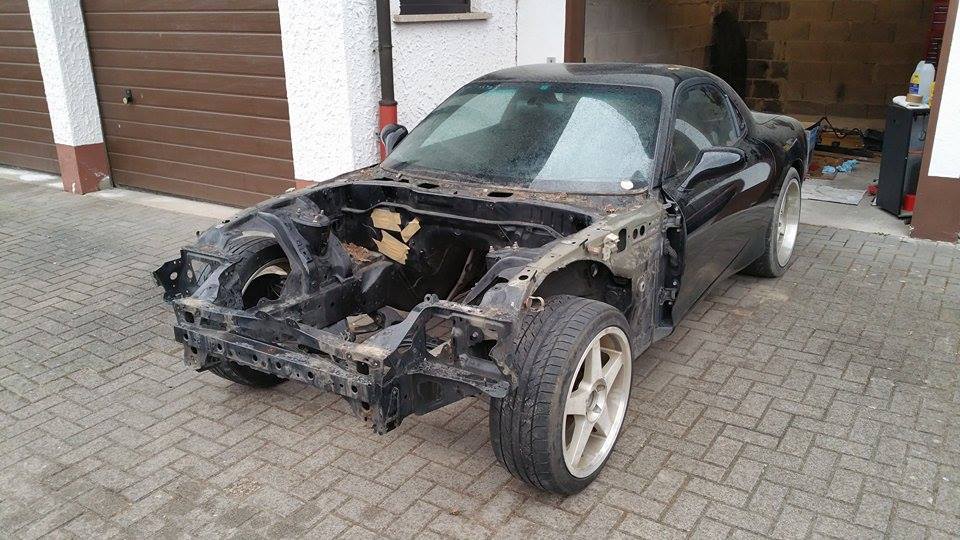
So, the plans on this build have changed a little. Rather than just rebuilding this car stock I have decided to do a mild build.
My plans are to have a mild single turbo set up, hopefully making around 450-475hp. I've been tearing the car apart slowly, I was in Korea for a few weeks so not much was accomplished. But, I'm ripping everything apart to have the front end steam cleaned so I can sand a touch up the paint in the engine bay.
She now sits like this.

Thread Starter
Full Member
Joined: Jan 2015
Posts: 59
Likes: 2
From: K-Town, Germany
A small amount of progress has been made today.
This fell out.......
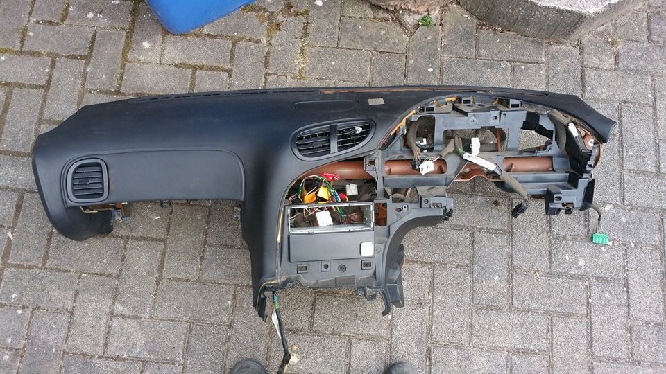
Followed by this............
The reason the harness is out is so I can replace the loom. The loom is dry and brittle at this point. Anybody have any good recommendations on what to replace it with?
Also, I cleaned up the rotors. I threw them in the electrolysis tank for 2 days and then everything basically wiped off.
This fell out.......

Followed by this............

The reason the harness is out is so I can replace the loom. The loom is dry and brittle at this point. Anybody have any good recommendations on what to replace it with?
Also, I cleaned up the rotors. I threw them in the electrolysis tank for 2 days and then everything basically wiped off.

Thread Starter
Full Member
Joined: Jan 2015
Posts: 59
Likes: 2
From: K-Town, Germany
So there's been a slight shift in the direction of this thread. I had planned on doing just an engine rebuild and planned the thread based on three sections: Removal, Rebuild, and Install. However, I'm now doing a lot more than just a rebuild. So I'm going to continue posting all the work I do. But when the engine rebuild begins, I'll start the Seasons back up.
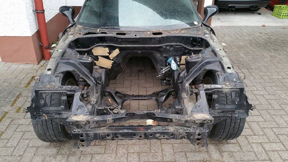
Anyways, I got more done today. The engine bay is pretty much stripped. I still need to pull the plastic clips that once held the wire harness in place, I need to remove the heater core and A/C core, and then the car will be ready to start prep'ing for paint.
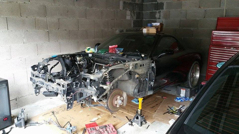
Finally got her back on all 4 wheels.
Engine bay is pretty well stripped.
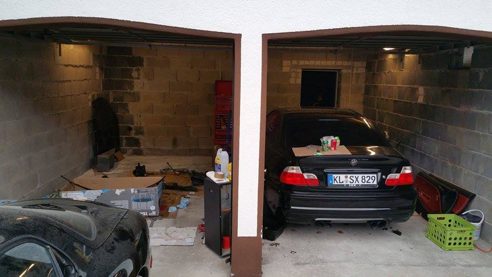
And the **** hole garage. I was dedicated to getting the car off stands, on wheels, and out of the garage so I can straighten the garage up tomorrow. That's my friends E46 M3 that I'm basically using as a table right now. lol. He planned on getting the calipers powder coated so he pulled them off a month ago, and he still hasn't gotten them to a powder coater. That's my justification for turning it into a table.
Anyways, I got more done today. The engine bay is pretty much stripped. I still need to pull the plastic clips that once held the wire harness in place, I need to remove the heater core and A/C core, and then the car will be ready to start prep'ing for paint.
Finally got her back on all 4 wheels.

Engine bay is pretty well stripped.

And the **** hole garage. I was dedicated to getting the car off stands, on wheels, and out of the garage so I can straighten the garage up tomorrow. That's my friends E46 M3 that I'm basically using as a table right now. lol. He planned on getting the calipers powder coated so he pulled them off a month ago, and he still hasn't gotten them to a powder coater. That's my justification for turning it into a table.

Thread Starter
Full Member
Joined: Jan 2015
Posts: 59
Likes: 2
From: K-Town, Germany
Well, it's been awhile since I've updated this.
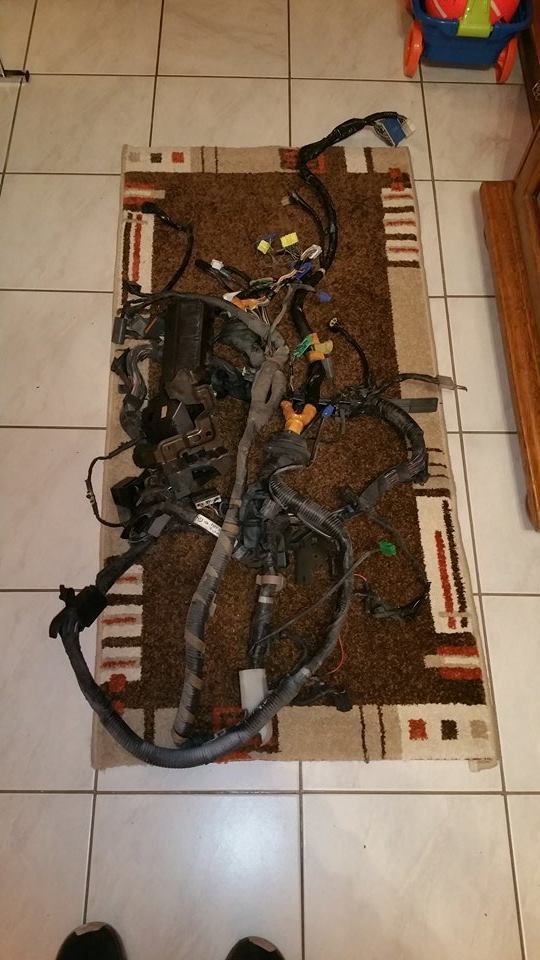
I spent the last two days completely stripping down the front body harness so I could put new loom on it. This is where I have her at now.
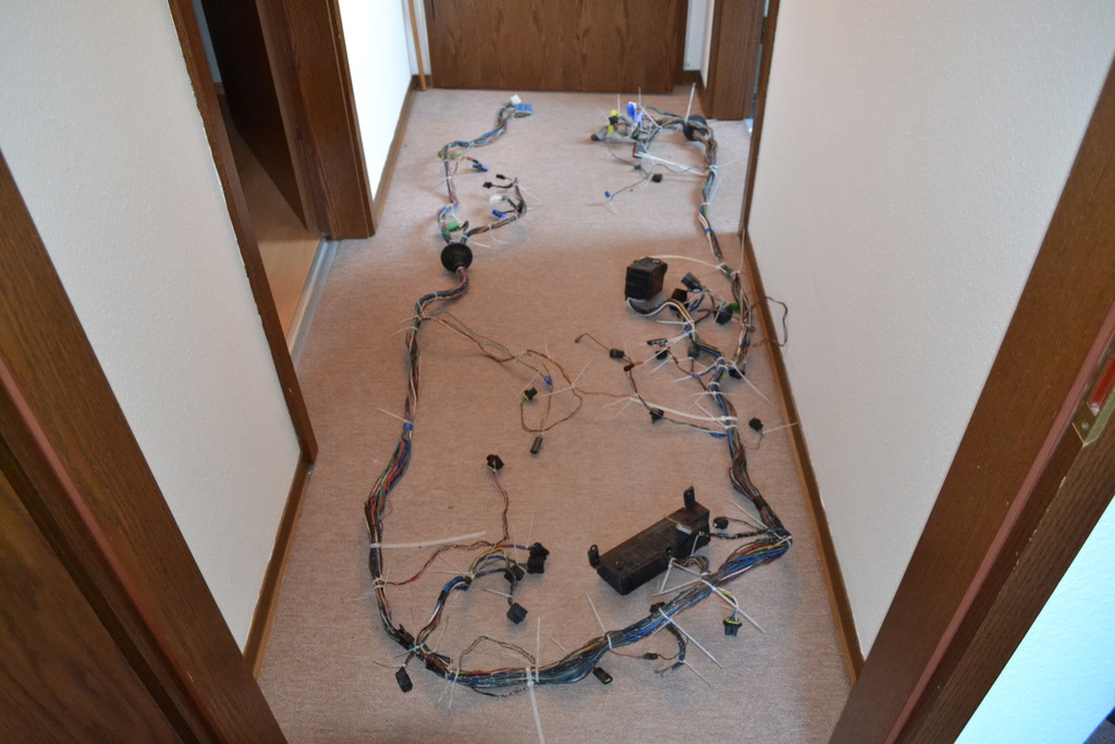
As you can see there about 15 billion zip ties. I used them to hold the basic shape of the harness, and more importantly at junctions in the harness to make sure I keep the branches at the right places.
Next up i will start removing the plugs so I can actually slide the mesh loom over the harness.
Thread Starter
Full Member
Joined: Jan 2015
Posts: 59
Likes: 2
From: K-Town, Germany
Quick update.
Since my last post, I got busy with removing all of the plugs, fuse boxes, and relay boxes on the harness. The reason for this is because I have to remove them to get the new harness material to slip over the wires. I'm wrapping the harness in a mesh wire loom.
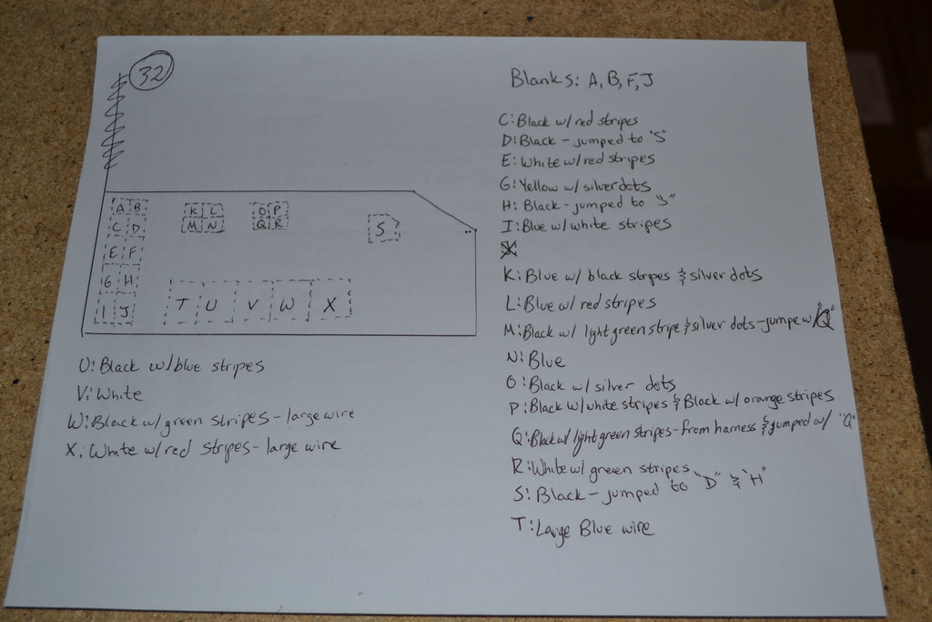
To remove the plugs, I first numbered each one and labeled which wires went where on diagrams that I drew. Below is an example of one. I'm sure this info is probably out there somewhere if I had bothered to look hard enough. But, I wanted to do it this way.
There's the harness with the 56 (I think), plugs and fuse/relay boxes removed. The plugs definitely aren't as hard to remove as you would expect. Once I got into the groove of removing them it didn't take a lot of time to get them off.
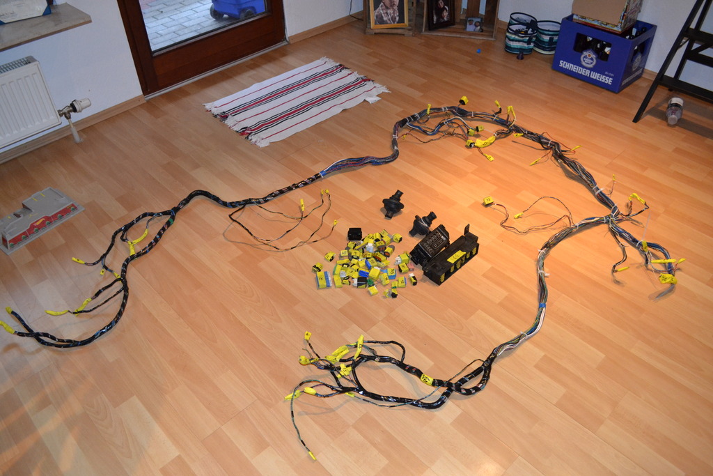
You can see that I have already begun to wrap the harness with electrical tape. Mainly on the ends where the harness is in the cabin. I'll continue wrapping the harness with electrical tape to help keep the harness' shape. Then later on will come the mesh loom.
More to come!!!
Since my last post, I got busy with removing all of the plugs, fuse boxes, and relay boxes on the harness. The reason for this is because I have to remove them to get the new harness material to slip over the wires. I'm wrapping the harness in a mesh wire loom.
To remove the plugs, I first numbered each one and labeled which wires went where on diagrams that I drew. Below is an example of one. I'm sure this info is probably out there somewhere if I had bothered to look hard enough. But, I wanted to do it this way.

There's the harness with the 56 (I think), plugs and fuse/relay boxes removed. The plugs definitely aren't as hard to remove as you would expect. Once I got into the groove of removing them it didn't take a lot of time to get them off.

You can see that I have already begun to wrap the harness with electrical tape. Mainly on the ends where the harness is in the cabin. I'll continue wrapping the harness with electrical tape to help keep the harness' shape. Then later on will come the mesh loom.
More to come!!!